tow BMW 540i 1998 E39 Owner's Manual
[x] Cancel search | Manufacturer: BMW, Model Year: 1998, Model line: 540i, Model: BMW 540i 1998 E39Pages: 1002
Page 488 of 1002
Downloaded from www.Manualslib.com manuals search engine
/ ~uel Tank and Fuel Pump
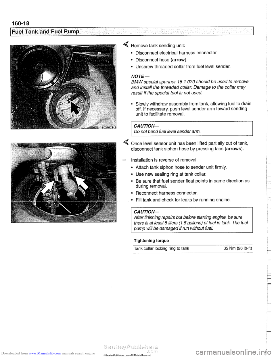
4 Remove tank sending unit:
Disconnect electrical harness connector.
Disconnect hose (arrow).
- Unscrew threaded collar from fuel level sender.
NOTE-
BMW special spanner 16 1 020 should be used to remove
and install the threaded collar. Damage to the collar may
result if the special tool is not used.
Slowly withdraw assembly from tank, allowing fuel to drain
off. If necessary, push level sender arm toward sending
unit to facilitate removal.
CA UTIOW-
Do not bend fuel level sender arm.
4 Once level sensor unit has been lifted partially out of tank,
disconnect tank siphon hose by pressing tabs (arrows).
- Installation is reverse of removal
Attach tank siphon hose to sender unit firmly.
Use new sealing ring at tank collar.
. Be sure that fuel sender float points in same direction as
during removal.
- Reconnect harness connector.
Fill tank and
check for leaks by running engine.
CAUTION-
After finishing repairs but before starting engine, be sure
there is at least
5 liters (1.5gallons) of fuel in tan/(. The fuel
pump will be damaged if run without fuel.
Tightening
torque
Tank collar loclting rlng to tanlt 35 Nm (26 lb-ft) -
Page 510 of 1002
Downloaded from www.Manualslib.com manuals search engine
Radiator and Cooling System
Cooling system, bleeding
Trapped air in the cooling system can prevent proper coolant
circulation and overheating. Wheneverthe coolant is drained
and filled, bleed the cooling system to remove trapped air.
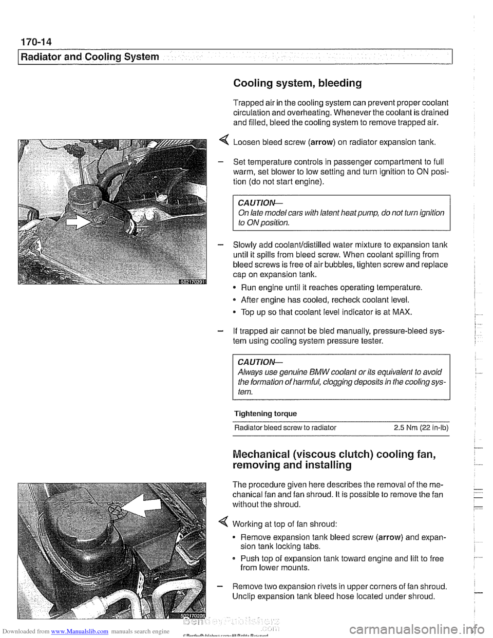
4 Loosen bleed screw (arrow) on radiator expansion tank.
- Set temperature controls in passenger compartment to full
warm, set blower to low setting and turn ignition to
ON posi-
tion (do not start engine).
CAUTIOIG
On late model cars with latent heat pump, do not turn ignition
to ON position.
- Slowly add coolanUdistilled water mixture to expansion tank
until it spills from bleed screw. When coolant spilling from
bleed screws is free of air bubbles, tighten screw and replace
cap on expansion tank.
Run engine until it reaches operating temperature,
- After engine has cooled, recheck coolant level.
Top up so that coolant level indicator is at MAX.
- If trapped air cannot be bled manually, pressure-bleed sys-
tem using cooling system pressure tester.
CA UTlON--
Always use genuine BMW coolant or its equivalent to avoid
the formation of harmful, clogging deposits
in the cooling sys-
tem.
Tightening torque
Radiator bleed screw to radiator 2.5 Nm (22 in-lb)
Mechanical (viscous clutch) cooling fan,
removing and installing
The procedure given here describes the removal of the me-
chanical fan and fan shroud. It is possible to remove the fan
without the shroud.
< Working at top of fan shroud:
Remove expansion tank bleed screw (arrow) and expan-
sion tank locking tabs.
Push top of expansion
tank toward engine and lift to free
from lower mounts.
- Remove two expansion rivets in upper corners of fan shroud.
Unclip expansion tank bleed hose located under shroud.
Page 520 of 1002
Downloaded from www.Manualslib.com manuals search engine
--
Radiator and Cooling System 1
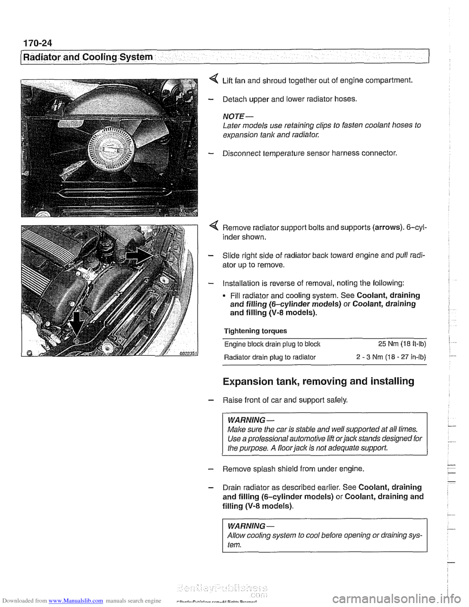
4 Lift fan and shroud together out of engine compartment.
- Detach upper and lower radiator hoses.
NOTE -
Later models use retaining clips to fasten coolant hoses to
expansion tank and radiator.
- Disconnect temperature sensor harness connector.
4 Remove radiator support bolts and supports (arrows). 6-cyl-
inder shown.
- Slide right side of radiator back toward engine and pull radi-
ator up to remove.
- Installation is reverse of removal, noting the following:
Fill radiator and cooling system. See Coolant, draining
and filling (6-cylinder models) or Coolant, draining
and filling (V-8 models).
Tightening torques
Engine block drain
plug to block 25 Nm (18 it-lb)
Radiator drain plug
to radiator 2 - 3 Nm (18 - 27 in-ib)
Expansion tank, removing and installing
- Raise front of car and support safely.
WARNING -
Make sure the car is stable and well supported at all times.
Use a professional automotive
/iff orjacltstands designed for
the purpose. A
floorjacl~ is not adequate support.
- Remove splash shield from under engine.
- Drain radiator as described earlier. See Coolant, draining
and filling (6-cylinder models) or Coolant, draining and
filling
(V-8 models).
I WARNING-
Allow cooling system to cool before opening or draining sys-
I tem.
Page 521 of 1002
![BMW 540i 1998 E39 Owners Manual Downloaded from www.Manualslib.com manuals search engine
170-25
Radiator and Cooling system]
< Disconnect expansion tank:
Remove expansion tank bleed screw and support clip
(A)
Loosen hose c BMW 540i 1998 E39 Owners Manual Downloaded from www.Manualslib.com manuals search engine
170-25
Radiator and Cooling system]
< Disconnect expansion tank:
Remove expansion tank bleed screw and support clip
(A)
Loosen hose c](/img/1/2822/w960_2822-520.png)
Downloaded from www.Manualslib.com manuals search engine
170-25
Radiator and Cooling system]
< Disconnect expansion tank:
Remove expansion tank bleed screw and support clip
(A)
Loosen hose clamp (6) and disconnect coolant hose from
expansion tank.
Disconnect harness connector from coolant level sensor
(C).
Push top of expansion tank toward engine and disconnect
bleed hose.
Lift expansion
tank to free it from lower mounts, then lift
straight up to remove.
- Installation is reverse of removal, noting the following:
Fill radiator and cooling system as described earlier. See
Coolant, draining and filling (6-cylinder models) or
Coolant, draining and filling
(V-8 models).
Page 529 of 1002
Downloaded from www.Manualslib.com manuals search engine
1 Exhaust ~vsteml
NOTE-
The front exhaust manifold must be removed before the rear
manifold.
- Installation is reverse of removal.
Coat exhaust mounting studs with CRC or equivalent cop-
per paste.
Use new gasltets and self-locking nuts.
Tightening torques Exhaust manifold to cylinder head 20 Nm
(15 ft-lb)
Front exhaust pipe to manifold 30 Nm
(22 ft-lb)
Oxygen sensor to manifold 50
Nrn (37 ft-lb)
Exhaust manifolds, removing and installing
(M62 engine)
Always use new retaining nuts and gasltets when removing
and installing the exhaust manifolds.
NOTE-
Access to manifolds is extremely limited. If removing exhaust
manifolds as part of additional engine worlc (such as cylinder
head removal), it may be easier to first remove engine.
- With exhaust system cold, raise and support car for access
to exhaust system.
WARNING -
Do not work undera lifted car unless it is solidly supported on
jaclt stands designed for the purpose. Never worlc undera car
that is supportedsolely
by a jack.
- Remove exhaust system. See Exhaust system, removing
and installing.
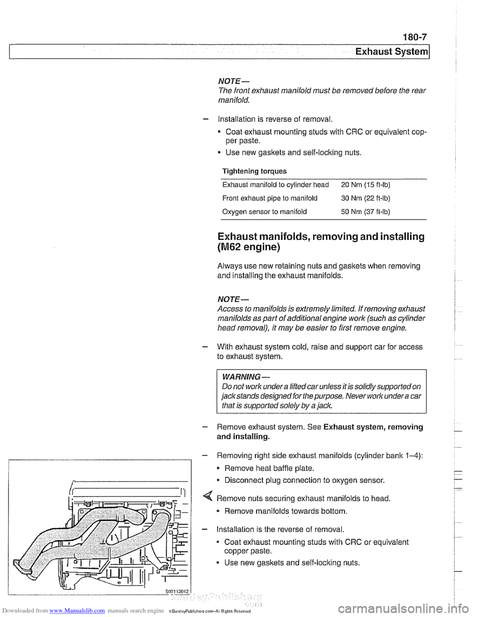
- Removing right side exhaust manifolds (cylinder bank 1-4):
Remove heat baffle plate.
Disconnect plug connection to oxygen sensor.
securing exhaust manifolds to head.
Remove manifolds towards bottom.
- Installation is the reverse of removal.
Coat exhaust mounting studs with CRC or equivalent
copper paste.
Use new gasltets and self-loclting nuts.
Page 530 of 1002
Downloaded from www.Manualslib.com manuals search engine
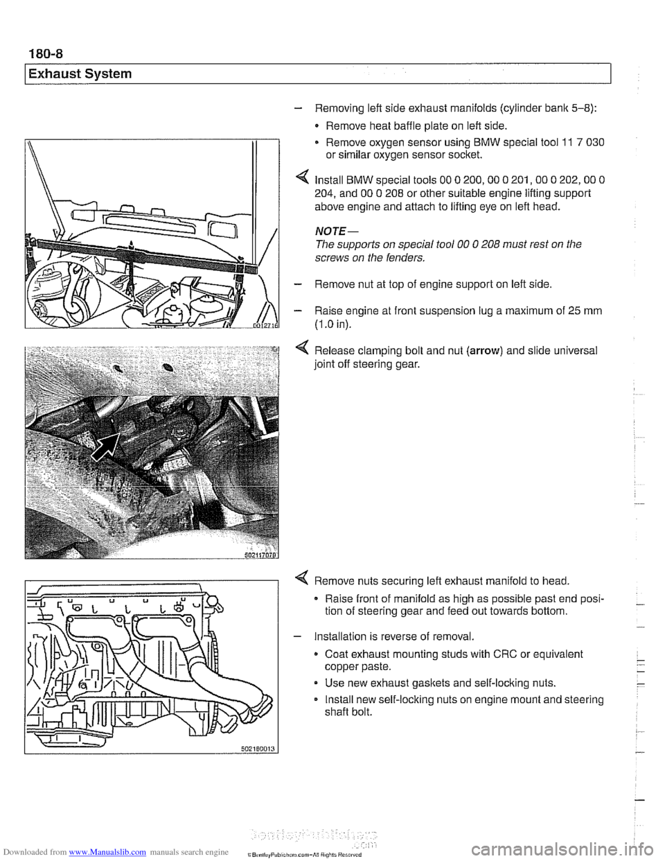
- Removing left side exhaust manifolds (cylinder bank 5-8):
- Remove heat baffle plate on left side.
Remove oxygen sensor using
BMW special tool 11 7 030
or similar oxygen sensor socket.
Install
BMW special tools 00 0 200,OO 0 201,OO 0 202,OO 0
204, and 00 0 208 or other suitable engine lifting support
above engine and attach to lifting eye on left head.
NOTE-
The supports on special tool 00 0 208 must rest on the
screws on the fenders.
- Remove nut at top of engine support on left side
- Raise engine at front suspension lug a maximum of 25 mm
(I
.O in).
Release clamping bolt and nut
(arrow) and slide universal
joint off steering gear.
4 Remove nuts securing left exhaust manifold to head,
Raise front of manifold as high as possible past end posi-
tion of steering gear and feed out towards bottom.
- Installation is reverse of removal.
Coat exhaust mounting studs with CRC or equivalent
copper paste.
Use new exhaust gaskets and self-locking nuts.
Install new self-locking nuts on engine mount and steering
shaft bolt.
Page 583 of 1002
Downloaded from www.Manualslib.com manuals search engine
Manual Transmission
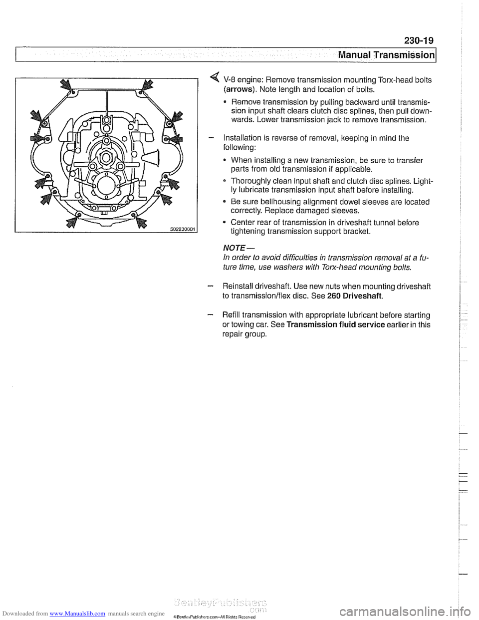
4 V-8 engine: Remove transmission mounting Tom-head bolts
(arrows). Note length and location of bolts.
Remove transmission by pulling backward until transmis-
sion input shaft clears clutch disc splines, then pull down-
wards. Lower transmission jack to remove transmission.
- Installation is reverse of removal, keeping in mind the
following:
When installing a new transmission, be sure to transfer
parts from old transmission
if applicable.
Thoroughly clean input shafl and clutch disc splines. Light-
ly lubricate transmission input shaft before installing.
* Be sure bellhousing alignment dowel sleeves are located
correctly. Replace damaged sleeves.
Center rear of transmission in driveshaft tunnel before
tightening transmission support bracket.
NOTE-
In order to avoid difficulties in transmission removal at a fu-
ture time, use washers with Torx-head mounting bolts.
- Reinstall driveshaft. Use new nuts when mounting driveshaff
to transmission/flex disc. See 260 Driveshaft.
- Refill transmission with appropriate lubricant before starting
or towing car. See Transmission fluid service earlier in this
repair group.
Page 584 of 1002
Downloaded from www.Manualslib.com manuals search engine
Manual Transmission
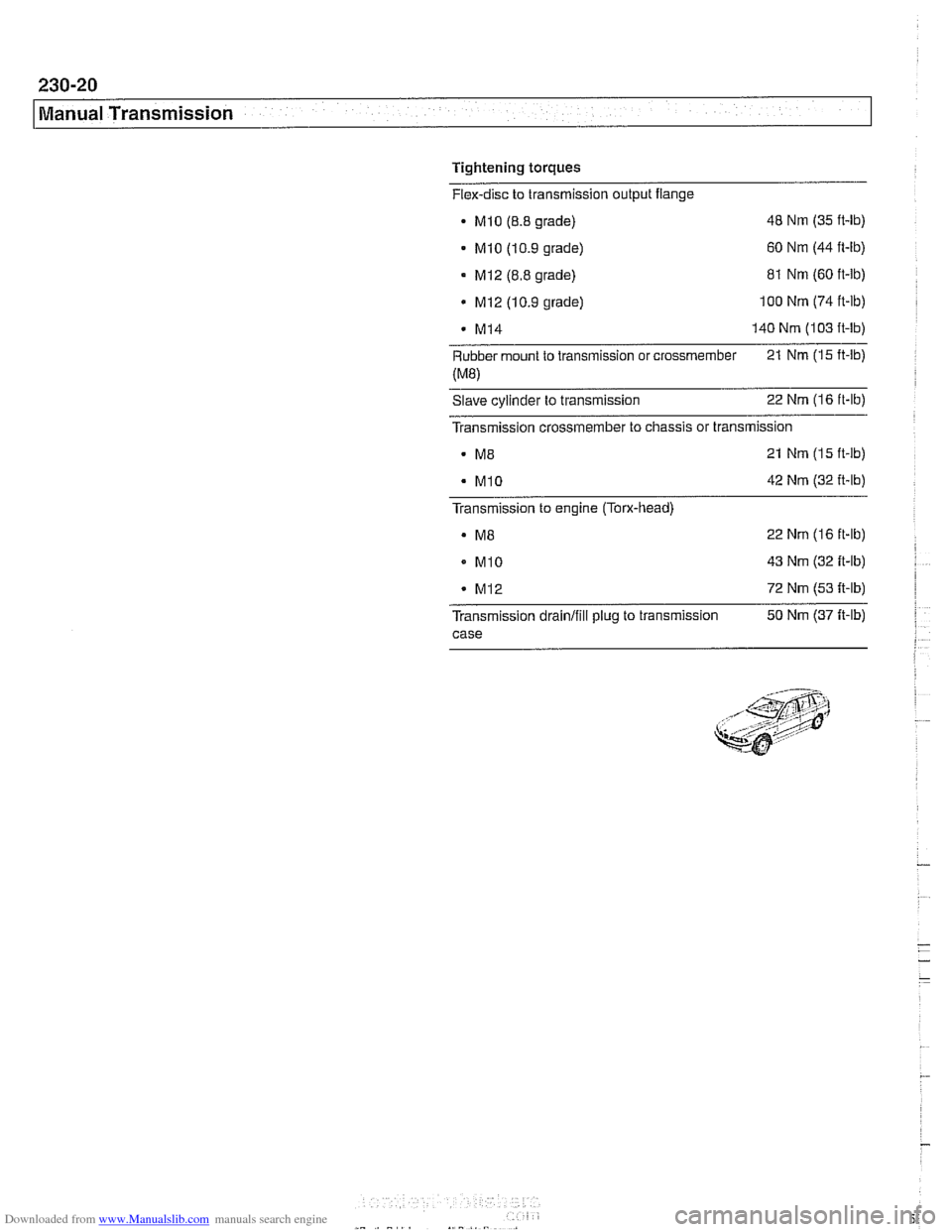
Tightening torques
Flex-disc to transmission output flange
- Mlo (8.8 grade) 48 Nm
(35 ft-lb)
- MI0 (10.9 grade) 60
Nm (44 ft-ib)
MI2 (8.8 grade)
MI2 (10.9 grade) 81
Nm (60 ft-ib) 100 Nm (74 ft-lb)
M14 140 Nm (103 ft-lb)
Rubber mount to transmission or crossmember 21
Nm (15 ft-lb)
(ME)
Slave cylinder to transmission 22 Nm (16
ft-lb)
Transmission crossmember to chassis or transmission
21 Nm
(15 ft-lb)
42 Nm (32 ft-lb)
Transmission to engine
(Towhead)
. M8 22 Nm (16 ft-lb)
MI0 43 Nm (32 ft-lb)
M12 72 Nm (53 It-lb)
Transmission drainlfili plug to transmission 50
Nm (37 It-lb)
case
Page 586 of 1002
Downloaded from www.Manualslib.com manuals search engine
240-2
/ ~utomatic Transmission
This section covers maintenance and replacement of the
automatic transmission for
E39 models.
Automatic transmission internal repairs are not covered.
Such repairs require special service equipment and knowl-
edge. If it is determined that transmission internal
sewice is
required, consult an authorized BMW dealer about a factory
reconditioned unit or a transmission rebuild.
CAUTION-
ATF does not circulate unless the engine is running. When
towing an automatic transmission vehicle, use a flat bed truck
or raise the rear wheels off the ground.
Special tools
Some special tools are required for the removal and installa-
tion of an automatic transmission on the
E39 BMW models.
While these tools are not absolutely necessary, they are es-
pecially helpful when dealing with the removal and replace-
ment of the torque converter.
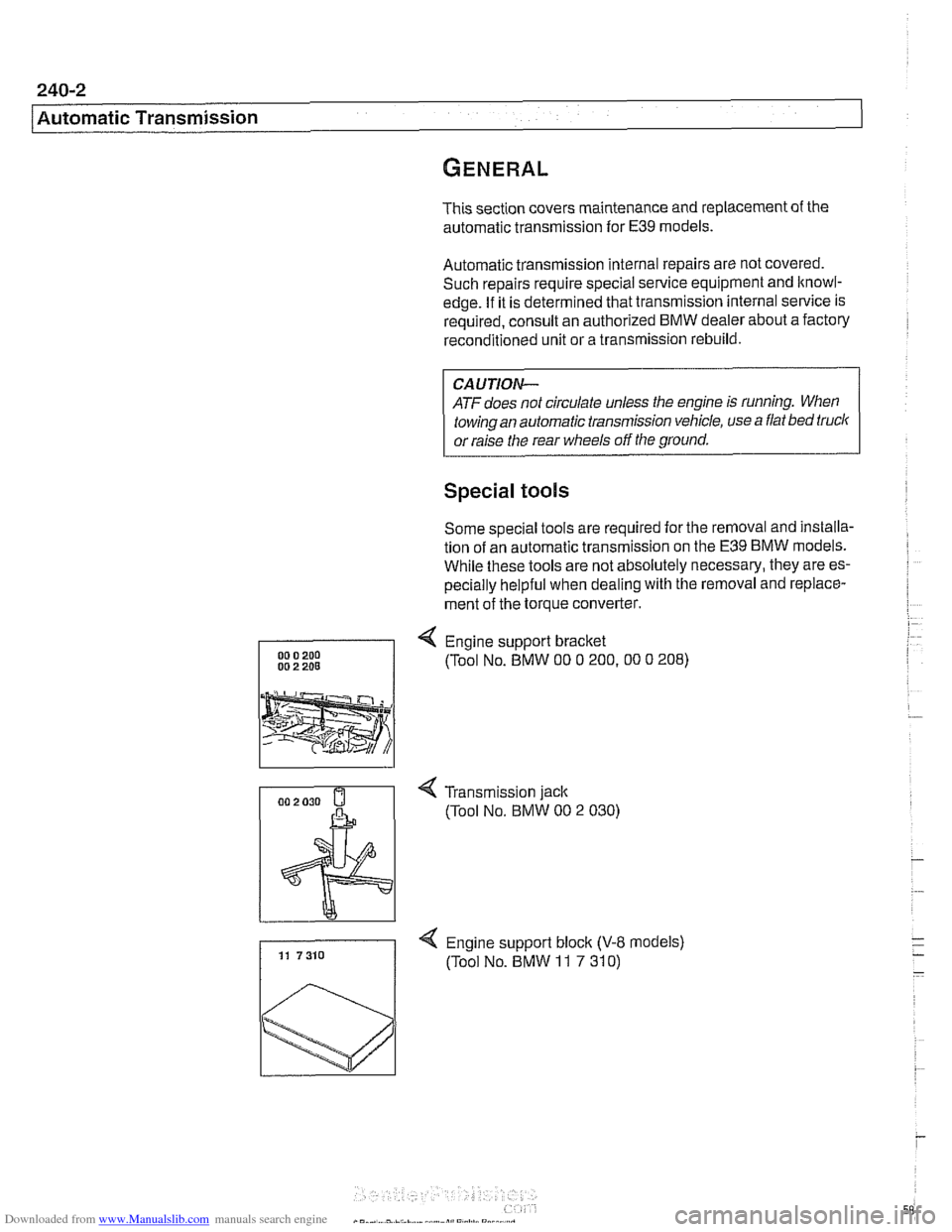
4 Engine support bracket
(Tool No. BMW
00 0 200.00 0 208)
4 Transmission jack
(Tool No.
BMW 00 2 030)
4 Engine support block (V-8 models) 11 7310 (Tool No. BMW 11 7 310)
Page 602 of 1002
Downloaded from www.Manualslib.com manuals search engine
250-4
I Gearshift Linkage
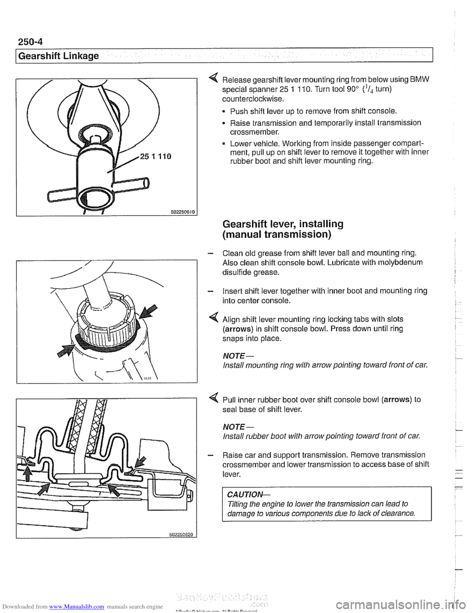
Release gearshift lever mounting ring from below using BMW
special spanner 25 1 110. Turn tool 90' ('I, turn)
counterclockwise.
Push shift lever up to remove from shift console,
Raise transmission and temporarily install transmission
crossmember.
Lower vehicle. Working from inside passenger compart-
ment, pull up on shift lever to remove it together with inner
rubber boot and shift lever mounting ring.
Gearshift lever, installing
(manual transmission)
- Clean old grease from shift lever ball and mounting ring.
Also clean shift console bowl. Lubricate with molybdenum
disulfide grease.
- Insert shift lever together with inner boot and mounting ring
into center console.
4 Align shift lever mounting ring locking tabs with slots
(arrows) in shift console bowl. Press down until ring
snaps into place.
NOTE-
lnstall mounting ring witli arrow pointing toward front of car.
4 Pull inner rubber boot over shift console bowl (arrows) to
seal base of shift lever.
NOTE-
lnstall rubber boot witli arrow pointing toward front of car.
- Raise car and support transmission. Remove transmission
crossmember and lower transmission to access base of shift
lever.
CAUTIOI\C
Tilting the engine to lower the transmission can lead to
damage to various components due to lack of clearance.