transmission oil BMW 540i 1998 E39 User Guide
[x] Cancel search | Manufacturer: BMW, Model Year: 1998, Model line: 540i, Model: BMW 540i 1998 E39Pages: 1002
Page 100 of 1002
Downloaded from www.Manualslib.com manuals search engine
11 3-6
Cylinder Head Removal and Installation
- Disable ignition system by removing DME main relay. See
610 Component Locations for relay location.
WARNING-
. The ignition system produces high voltages that can be fa-
tal. Avoid contact with exposed terminals and use
exfreme
caution when working on a car with the ignition switched on
or the engine running.
Do not touch or disconnect ignition
components while
the engine is running or being cranked by the starter.
Failure to remove the DME main relay or attempting to
disa-
bie the fuel andignition systems by other methods may result
in damaoe to the enoine control module
(ECM).
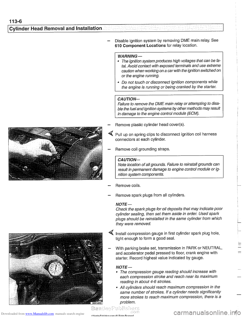
- - Remove plastic cylinder head cover(s)
,,I . ,. .*,.,,&- - Remove coil grounding straps.
I CAUTION-
I nition system components. I
- Remove coils.
- Remove spark plugs from all cylinders.
NOTE-
Check the spark plugs for oil deposits that may indicate poor
cylinder sealing, then set them aside in order. Used spark
plugs should be reinstalled in the same cylinder from which
they were removed.
4 Install compression gauge in first cylinder spark plug hole,
tight enough to form a good seal.
- With parking brake set, transmission in PARK or NEUTRAL,
and accelerator pedal pressed to floor, crank engine with
starter. Record highest value indicated by gauge.
NOTE-
* The compression gauge reading should increase with
each compression stroke and reach near its maximum
reading in about
4-6 strokes.
All cylinders should reach maximum compression in the
same number of
strolces. If a cylinder needs significantly
more strokes to reach
maximum compression, there is a
problem.
Page 148 of 1002
Downloaded from www.Manualslib.com manuals search engine
. ." ".
[Cylinder Head Removal and Installation - .. - -1 -
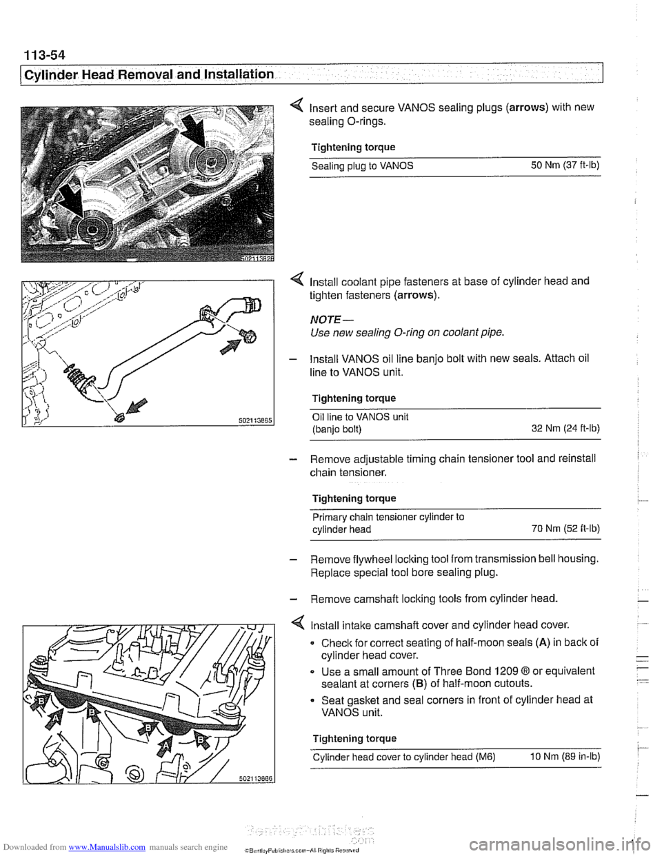
4 Insert and secure VANOS sealing plugs (arrows) with new
sealing O-rings.
Tightening torque Sealing
plug to VANOS 50
Nm (37 ft-lb)
4 Install coolant pipe fasteners at base of cylinder head and
tighten fasteners (arrows).
NOTE-
Use new sealing O-ring on coolant pipe.
- lnstall VANOS oil line banjo bolt with new seals. Attach oil
line to VANOS unit.
Tightening torque Oil line to VANOS unit
(banjo bolt) 32
Nm (24 ft-ib)
- Remove adjustable timing chain tensioner tool and reinstall
chain tensioner.
Tightening torque Primary chain tensioner cylinder to
cylinder head 70
Nm
(52 fi-ib)
- Remove flywheel locking tool from transmission bell housing.
Replace special tool bore sealing plug.
- Remove camshaft locking tools from cylinder head
4 lnstall intake camshaft cover and cylinder head cover.
0 Check for correct seating of half-moon seals (A) in back of
cylinder head cover.
Use a small amount of Three Bond
1209 8 or equivalent
sealant at corners
(B) of half-moon cutouts.
Seat gasket and seal corners in front of cylinder head at
VANOS unit.
Tightening torque
Cylinder head cover to cylinder head
(M6) 10 Nm (89 in-lb)
Page 284 of 1002
Downloaded from www.Manualslib.com manuals search engine
-
I Camshaft Timing Chain - --
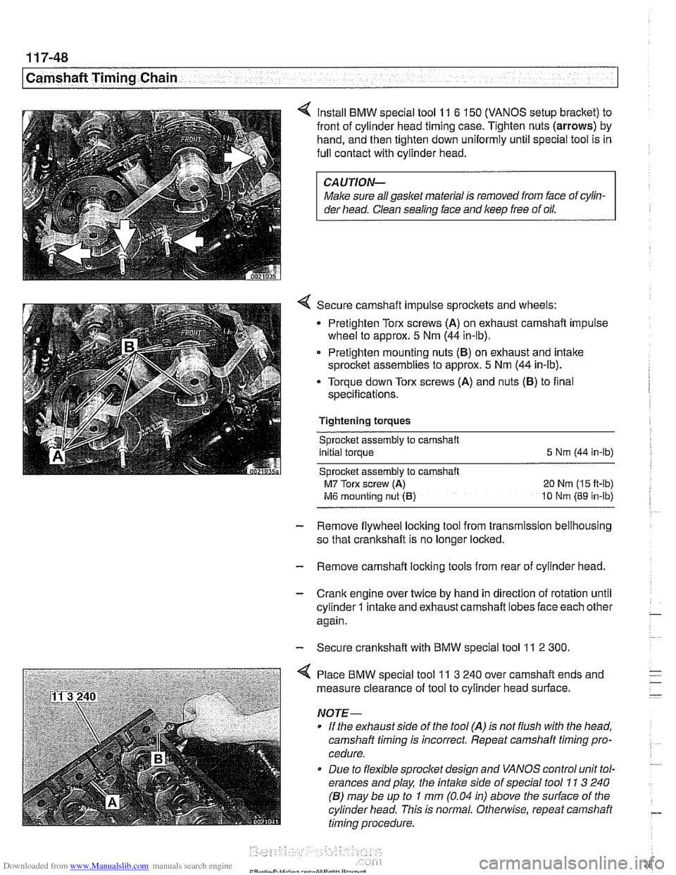
Install BMW special tool 11 6 150 (VANOS setup bracket) to
front of cylinder head timing case. Tighten nuts
(arrows) by
hand, and then tighten down uniformly until special tool is in
full contact with cylinder head.
CAUTION-
Male sure all gasket material is removed from face of cylin-
der head. Clean
sealins face and keep free of oil.
Secure camshaft impulse sprockets and wheels:
Pretighten Torx screws
(A) on exhaust camshaft impulse
wheel to approx.
5 Nm (44 in-lb).
Pretighten mounting nuts
(B) on exhaust and intake
sprocket assemblies to approx.
5 Nm (44 in-lb).
- Torque down Torx screws (A) and nuts (8) to flnal
specifications.
Tightening torques Sprocket assembly
to camshaft
initial torque
5 Nm (44 in-lb)
Sprocket assembly to camshaft
M7 Torx screw (A) 20 Nm (15 fl-lb)
ivl6 mounting nut (B) 10 tdm (89 in-lb)
- Remove flywheel locking tool from transmission bellhousing
so that crankshaft is no longer locked.
- Remove camshaft locking tools from rear of cylinder head.
- Crank engine over twice by hand in direction of rotation until
cylinder
1 intake and exhaust camshaft lobes face each other - again.
- Secure crankshaft with BMW special tool 11 2 300.
4 Place BMW special tool 11 3 240 over camshaft ends and
measure clearance of tool to cylinder head surface.
NOJE-
If the exhaust side of the tool (A) is not flush with the head,
camshaft timing
Is incorrect. Repeat camshaft timing pro-
cedure.
* Due to flexible sprocket design and VANOS control unit tol-
erances and play, the
intake side of special tool 11 3 240
(6) may be up to 1 mm (0.04 in) above the sudace of the
cylinder head. This is normal. Otherwise, repeat camshaft
timing procedure.
Page 285 of 1002
Downloaded from www.Manualslib.com manuals search engine
-- - -- - -- Camshaft Timing chain1
- Remove camshaft locking tools from rear of camshafts
- Remove BMW special tool 11 4 220 (adjustable primary
chain tensioner). Reinstall primary chain tensioner.
Tightening torque Primary chain tensioner to cylinder head
70
Nm (52 it-lb)
- Remove crankshaft locking tool from transmission bellhous-
ing. Reinstall sealing plug.
- Remove VANOS setup bracket from front of cylinder head
- lnstall VANOS control unit as described earlier in this group.
- Remove compressed air fitting (BMW special tool 11 3 450)
from VANOS control unit.
- Fit VANOS oil line banjo bolt with new seals. Attach oil line to
VANOS control unit.
Tightening torque
Oil line to VANOS control unit (banjo bolt) 32 Nm (24 H-lb)
- Remainder of installation is reverse of removal, noting the fol-
lowing:
lnstall spark plugs.
* lnstall intake camshaft plastic baffle prior to installing cylin-
der head cover. lnstall ignition coil packs and connect elec-
trical harness connectors.
Install radiator cooling fan.
- lnstall air filter housing and top engine cover.
Tightening torque Radiator cooling fan
(VISCOUS clutch) to 40 Nm (30 ft-lb)
coolant pump
Cyitnder head cover to cylinder head 10 Nm (89 in-lb)
Sparlc plug to cylinder head 25 Nm (18 ft-lb)
Page 301 of 1002
Downloaded from www.Manualslib.com manuals search engine
Cp-- Camshaft -- Timing Chain
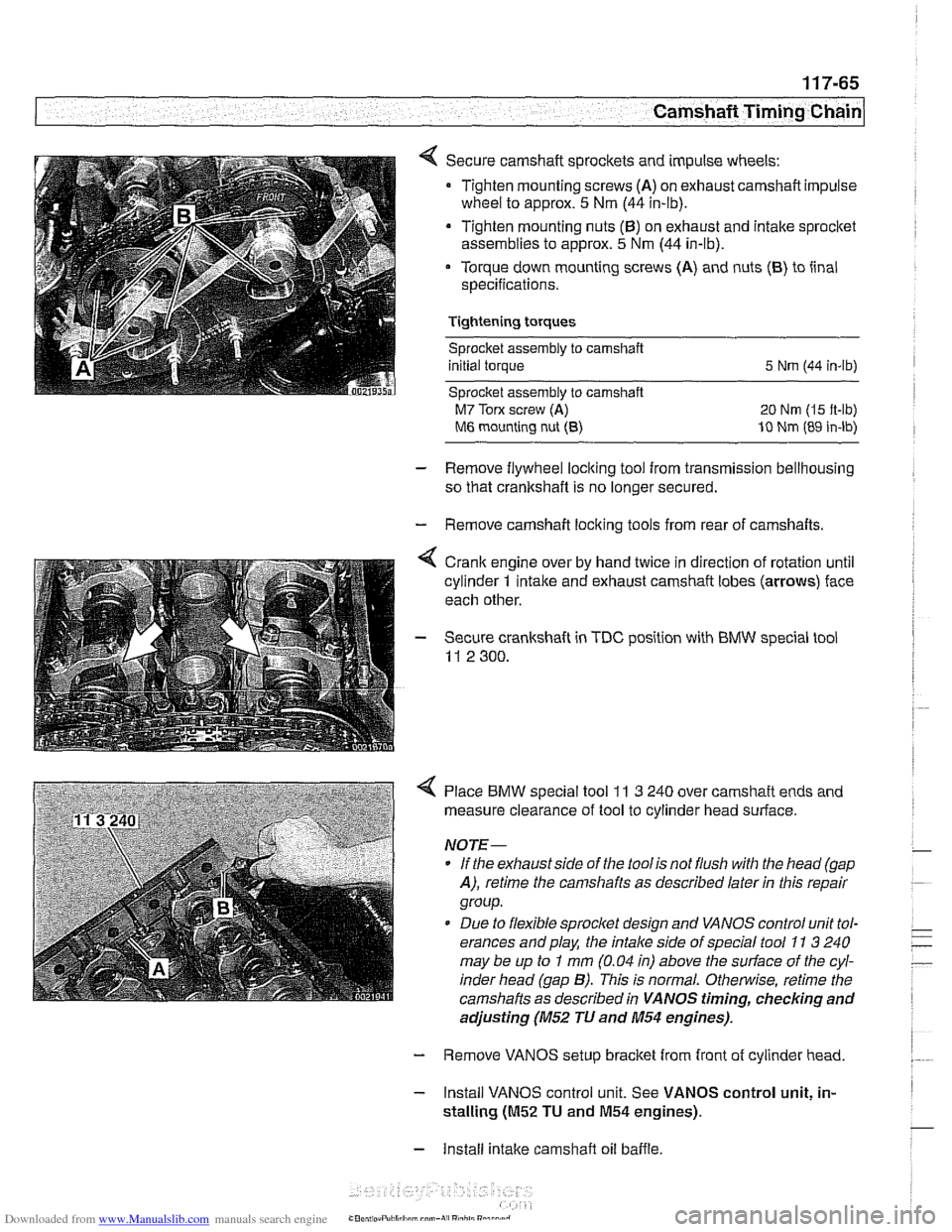
Secure camshaft sprockets and impulse wheels:
Tighten mounting screws
(A) on exhaust camshaft impulse
wheel to approx.
5 Nm (44 in-lb).
Tighten mounting nuts
(6) on exhaust and intake sprocket
assemblies to approx.
5 Nm (44 in-lb).
Torque down mounting screws (A) and nuts
(6) to iinal
specifications.
Tightening torques Sprocket assembly
to camshaft
initial torque
5 Nrn (44 in-lb)
Sprocket assembly to camshaft
M7 Torx screw (A) 20 Nm (I5 it-lb)
M6 mounting nut (8) 10 Nm (89 in-lb)
- Remove flywheel locking tool from transmission bellhousing
so that crankshaft is no longer secured.
- Remove camshaft loclting tools from rear of camshafts.
4 Crank engine over by hand twice in direction of rotation until
cylinder
1 intake and exhaust camshaft lobes (arrows) face
each other.
- Secure crankshaft in TDC position with BMW special tool
11 2 300.
4 Place BMW special tool 11 3 240 over camshaft ends and
measure clearance of tool to cylinder head surface.
NOTE-
* If the exhaust side of the tool is not flush with the head (gap
A), retime the camshafts as described laler in this repair
group.
Due to flexible sprocket design and VANOS control unit tol-
erances and play, the
intake side of special tool 71 3 240
may be up to
I mm (0.04 in) above the suriace of the cyl-
inder head (gap
B). This is normal. Otherwise, retime the
camshafts as described in
VANOS timing, checking and
adjusting (M52 TU and 11154 engines).
- Remove VANOS setup bracket from front of cylinder head
- Install VANOS control unit. See VANOS control unit, in-
stalling
(01152 TU and M54 engines).
- Install intake camshaft oil baffle
Page 322 of 1002
Downloaded from www.Manualslib.com manuals search engine
11 9-2
Lubrication System
This repair group covers lubrication system troubleshooting
as well as oil pan removal and oil pump replacement.
In 6-cylinder models, removal of the oil pan requires the re-
moval of the exhaust system and some front suspension
components. Those procedures are fully covered in:
180 Exhaust System
210 Clutch
230 Manual Transmission
0 240 Automatic Transmission
310 Front Suspension
320 Steering and Wheel Alignment
NOTE-
Oil change procedure and oil filter replacement are covered
in
020 Maintenance.
CAUTIOG
V8 engines: The oil pump fasteners (including the sprocket
retaining nut) are known to vibrate loose. This can result in oil
starvation and engine failure. Be sure to check oil bolts and
nut tightness whenever the
oilpump is accessible. If any fas-
teners are found to be loose, remove them and reinstall with
Loctite
Band torque to specifications.
Special tools
The engine needs to be properly supported while the front
suspension
subframe is lowered to access the oil pan.
A standard oil pressure gauge may be used for measuring oil
pressure.
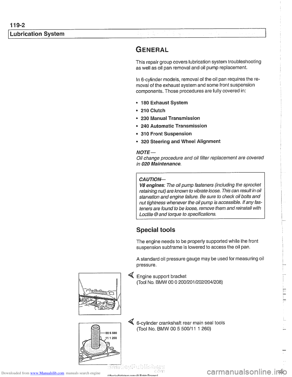
Engine support bracket
(Tool No, BMW 00 0 20012011202~2041208)
4 6-cylinder crankshalt rear main seal tools
(Tool No. BMW 00 5 50011
1 1 260)
Page 326 of 1002
Downloaded from www.Manualslib.com manuals search engine
Lubrication System
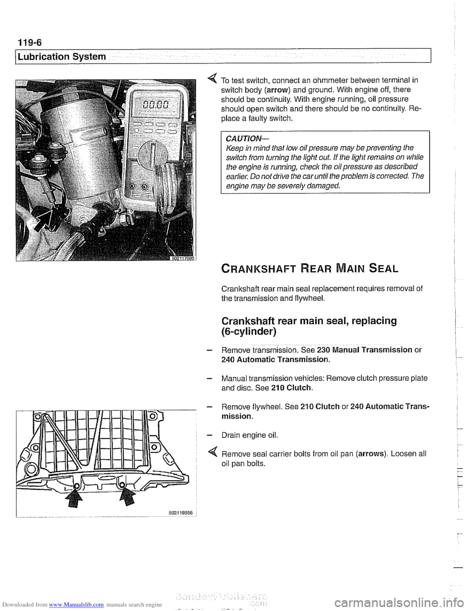
To test switch, connect an ohmmeter between terminal in
switch body (arrow) and ground. With engine off, there
should be continuity. With engine running, oil pressure
should open switch and there should be no continuity. Re-
place a faulty switch.
CAUTION-
Keep in mind that low oil pressure may be preventing the
switch from turning the light out
If the light remains on while
the engine is running, check the oil pressure as described
earlier. Do not drive the car until the problem is corrected. The
engine may be severely damaged.
Crankshaft rear main seal replacement requires removal of
the transmission and flywheel.
Crankshaft rear main seal, replacing
(&cylinder)
- Remove transmission. See 230 Manual Transmission or
240 Automatic Transmission.
- Manual transmission vehicles: Remove clutch pressure plate
and disc. See
210 Clutch.
- Remove flywheel. See 210 Clutch or 240 Automatic Trans-
mission.
- Drain engine oil.
4 Remove seal carrier bolts from oil pan (arrows). Loosen all
oil pan bolts.
Page 328 of 1002
Downloaded from www.Manualslib.com manuals search engine
I Lubrication System -
- Remainder of assembly is reverse of disassembly.
Install flywheel, clutch or torque converter and
transmission.
Fill engine with oil.
- Run engine and check for leaks.
Tightening torques
Oil
drain plug fo oil pan (MI21 25 Nm (18 ft-lb)
Oil pan to engine
block
M6 (8.8 grade) 10 Nm (89 in-ib)
M6 (1 0.9 grade) 12 Nm (9 ft-lb)
M8 (8.8 grade) 22 Nm (1 6 it-lb)
Rear main seal carrier to crankcase
M6 10 Nm (89 in-lb)
ME 22 Nm (16 ft-lb)
Crankshaft rear main seal, replacing (V-8)
- Remove transmission. See 230 Manual Transmission or
240 Automatic Transmission.
- Manual transmission vehicles: Remove clutch pressure plate
and disc. See
210 Clutch.
- Remove flywheel. See 210 Clutch.
- Drain engine oil.
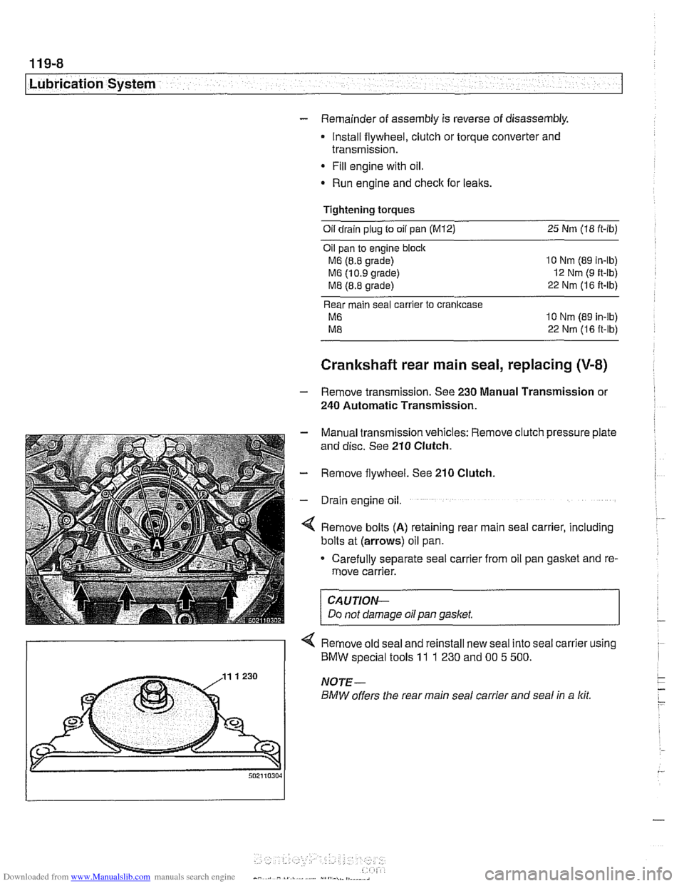
4 Remove bolts (A) retaining rear main seal carrier, including
bolts at (arrows) oil pan.
Carefully separate seal carrier from oil pan gasket and re-
move carrier.
CAUTION-
Do not damage oil pan gasket.
< Remove old seal and reinstall new seal into seal carrier using
) BMW special tools 11 1 230 and 00 5 500.
Page 329 of 1002
Downloaded from www.Manualslib.com manuals search engine
- When reinstalling seal carrier to crankcase:
Check locating sleeves for damage.
Replace gasitet between rear main seal carrier and
cranlt-
case.
Apply thin coat of
3 Bond 8 1209 or equivalent sealant to
oil pan
gasltet sealing surfaces.
* Lubricate crankshaft and seal contact surfaces.
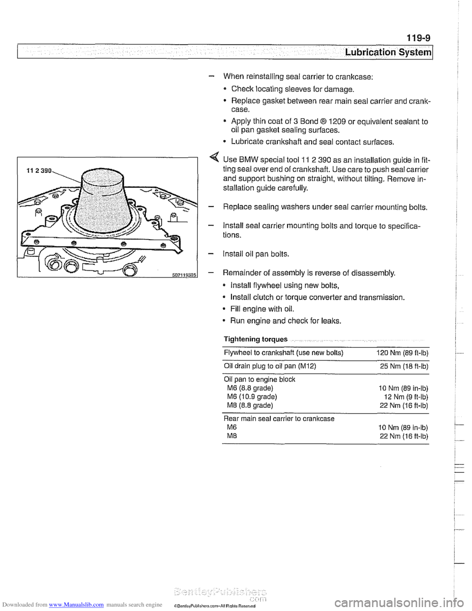
4 Use BMW special tool 11 2 390 as an installation guide in fit-
ting seal over end of cranltshaft. Use care to push seal carrier
and support bushing on straight, without tilting. Remove in-
stallation guide carefully.
- Replace sealing washers under seal carrier mounting bolts.
- Install seal carrier mounting bolts and torque to specilica-
tions.
- lnstall oil pan bolts.
- Remainder of assembly is reverse of disassembly.
Install flywheel using new bolts,
Install clutch or torque converter and transmission.
* Fill engine with oil.
Run engine and
checlt for leaks.
Tightening torques Flywheel to crankshaft (use new bolts)
120 Nm (89 ft-lb)
011 dra~n plug to 011 pan (M12) 25 Nm (18 ft-lb)
Oil pan to
eng~ne block
M6 (8.8 grade) 10 Nm (89 in-lb)
M6 (1 0 9 grade) 12 Nm (9 ft-lb)
M8 (8.8 grade) 22 Nm (16 ft-lb)
Rear main seal carrier to crankcase
M6 10 Nrn (89 in-lb)
ME 22 Nm (16 ft-lb)
Page 331 of 1002
Downloaded from www.Manualslib.com manuals search engine
Lubrication system/
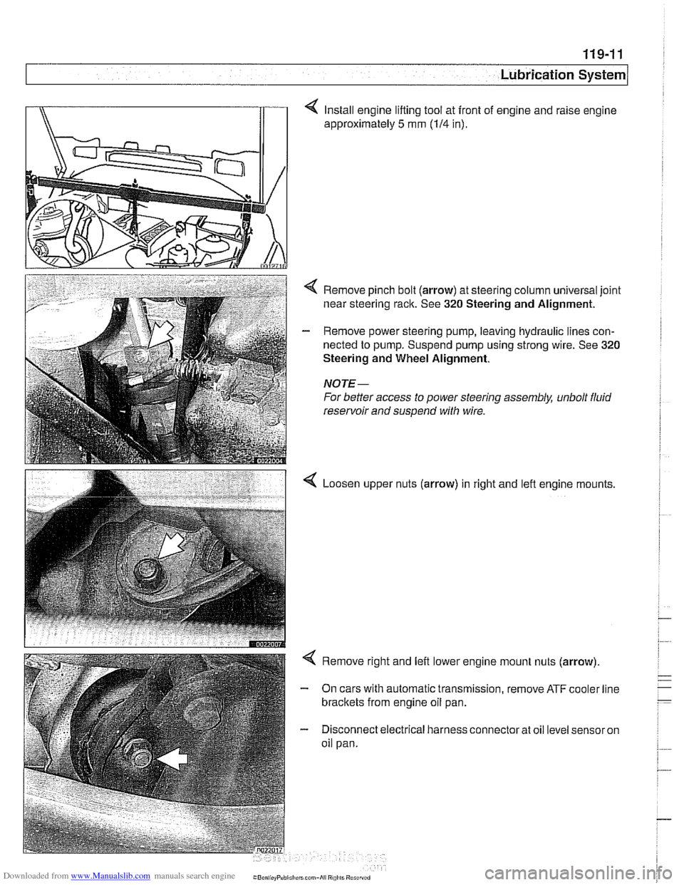
4 Install engine lifting tool at front of engine and raise engine
approximately
5 mm (114 in).
< Remove pinch bolt (arrow) at steering column universal joint
near steering rack. See
320 Steering and Alignment.
- Remove power steering pump, leaving hydraulic lines con-
nected to pump. Suspend pump using strong wire. See
320
Steering and Wheel Alignment.
NOTE-
For better access to power steering assembly, unbolt fluid
reservoir and suspend with wire.
Loosen upper nuts (arrow) in right and lefl engine mounts,
< Remove right and left lower engine mount nuts (arrow)
- On cars with automatic transmission, remove ATF cooler line
brackets from engine oil pan.
- Disconnect electrical harness connector at oil level sensor on
oil pan.