transmission oil BMW 540i 1998 E39 Owner's Manual
[x] Cancel search | Manufacturer: BMW, Model Year: 1998, Model line: 540i, Model: BMW 540i 1998 E39Pages: 1002
Page 332 of 1002
Downloaded from www.Manualslib.com manuals search engine
119-12
Lubrication System 1
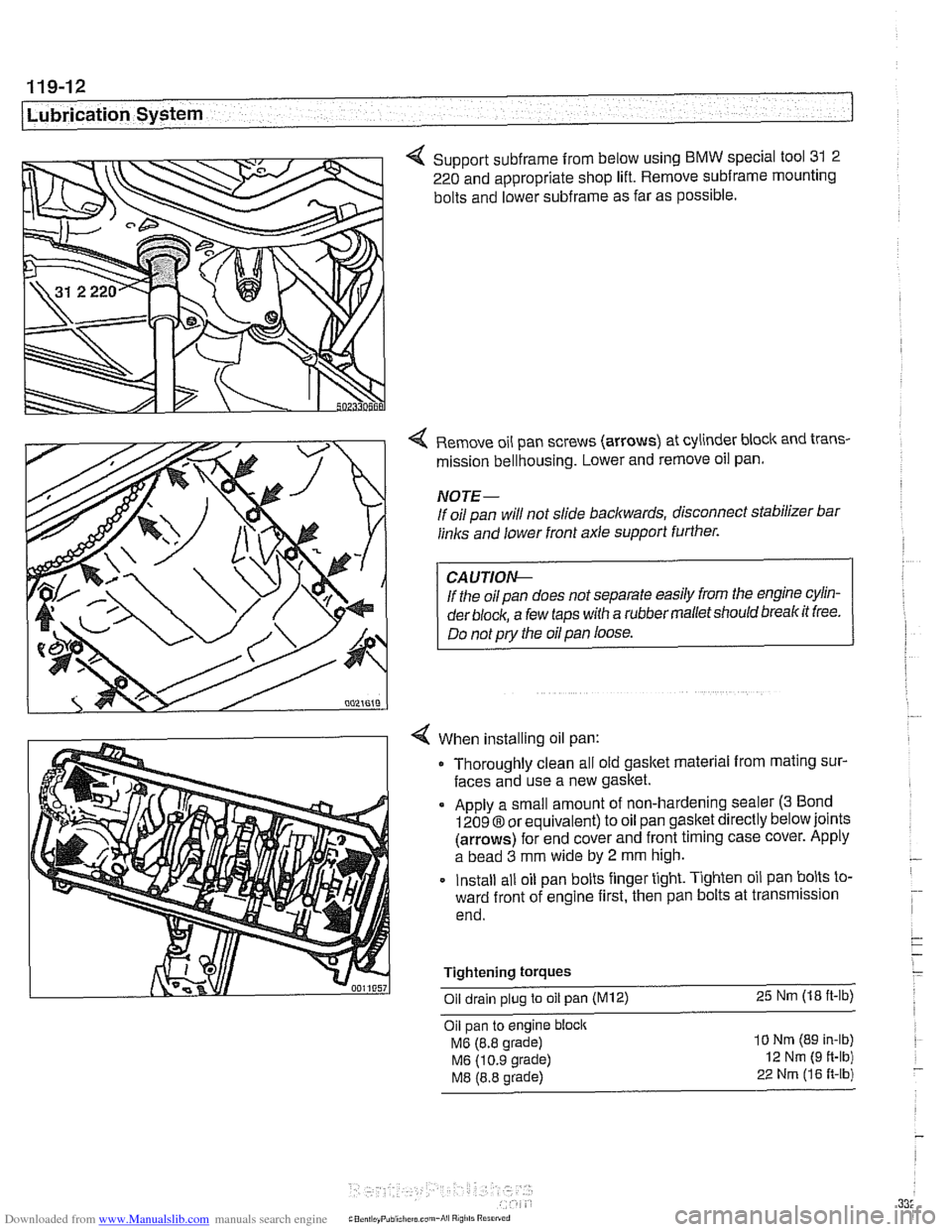
4 Support subframe from below using BMW special tool 31 2
220 and appropriate shop lift. Remove
subframe mounting
bolts and lower
subframe as far as possible.
Remove oil pan screws (arrows) at cylinder block and trans-
mission bellhousing. Lower and remove oil pan.
NOTE-
If oil pan will not slide backwards, disconnect stabilizer bar
links and lower front axle support further.
If the oil pan does not separate easily from the engine cylin-
der
block, a few taps with a rubber malletshould breakit free.
Do not
pry the oil pan loose.
When installing oil pan: Thoroughly clean all old gasket material from mating sur-
faces and use a new gasket.
Apply a small amount of non-hardening sealer
(3 Bond
12098 or equivalent) to oil pan gasket directly below joints
(arrows) for end cover and front timing case cover. Apply
a bead
3 mm wide by 2 mm high.
Install all oil pan bolts finger tight. Tighten oil pan bolts to-
ward front of engine first, then pan bolts at transmission
end.
Tightening
torques
Oil drain plug to oil pan (M12) 25 Nm (18 ft-lb)
Oil pan to engine block
MG (8.8 grade)
MG (10.9 grade)
M8 (8.8 grade)
10 Nm (89 In-lb)
12 Nm (9 ft-lb)
22 Nrn (16 R-lb)
Page 333 of 1002
![BMW 540i 1998 E39 Owners Manual Downloaded from www.Manualslib.com manuals search engine
-- . - .. . - Lubrication system]
- Remainder of installation is reverse of removal.
Replace self-locking nuts when reinstalling front BMW 540i 1998 E39 Owners Manual Downloaded from www.Manualslib.com manuals search engine
-- . - .. . - Lubrication system]
- Remainder of installation is reverse of removal.
Replace self-locking nuts when reinstalling front](/img/1/2822/w960_2822-332.png)
Downloaded from www.Manualslib.com manuals search engine
-- . - .. . - Lubrication system]
- Remainder of installation is reverse of removal.
Replace self-locking nuts when reinstalling front suspen-
sion components.
Use new oil dipstick tube sealing O-ring.
After adding engine oil, start and run engine. Raise engine
speed to 2,500 rpm until oil pressure warning light goes out
(about 5 seconds).
NOTE-
BMW does not specify a front end alignment following this
procedure.
Tightening torques Front subfrarne to body rail
(M12, use new bolts)
8.8 grade
10.9 grade
12.9 grade 77 Nrn
(57 ft-lb)
105 Nrn (77 ft-lb)
110 Nrn (81 ft-lb)
Stabilizer bar link to stabilizer bar
65 Nrn (48 ft-lb)
Steering shaft universal joint clamping bolt
(use new bolt)
19 Nrn (14 it-lb)
Lower oil pan, removing and installing (V-8)
- The V-8 engine is equipped with a 2-piece oil pan. The fas-
teners in
V-8 engine oil pump assembly, including the
sprocket retaining nut, are known to loosen and fall off into
the oil pan. Be sure to install these fasteners with Loctite
O
or equivalent thread locking product and torque to specifica-
tions.
CAUTION-
It is recommended that the oil pump retaining bolts and oil
pump drive sprocket retaining nut tightening torque be
checkedany time the
oilpan is removed.
- Raise car and place securely on jack stands.
WARNING-
Make sure the car is stable and well supported at all times.
Use a professional automotive lift
orjack stands designed for
- Remove splash shield from under engine.
- Drain engine oil
- On cars with automatic transmission, remove ATF cooler line
brackets from oil pan.
Page 340 of 1002
Downloaded from www.Manualslib.com manuals search engine
Lubr~cat~on System r- -
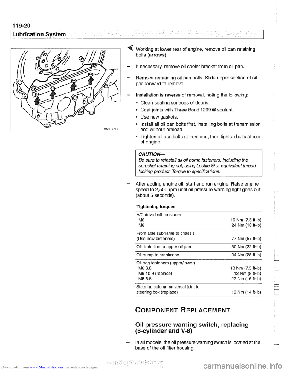
Working at lower rear of engine, remove oil pan retaining
bolts
(arrows).
- If necessary, remove oil cooler bracket from oil pan.
- Remove remaining oil pan bolts. Slide upper section of oil
pan forward to remove.
- Installation is reverse of removal, noting the following:
Clean sealing surfaces of debris.
- Coat joints with Three Bond 1209 O sealant.
Use new gaskets.
Install all oil pan bolts first, installing bolts at transmission
end without preload.
Tighten oil pan bolts at front end, then tighten bolts at rear
of engine.
Be sure to reinstall all oil
pump fasteners, including the
sprocl
speed to
2,500 rpm until oil pressure warning light goes out
(about
5 seconds).
Tightening torques
AIC drive belt tensloner
M6 10 Nm (7.5 it-lb)
M8 24 Nm (18 ft-lb)
Front axle
subframe to chassis
(Use new fasteners) 77 Nm (57 ft-lb)
Oil drain
line to upper oil pan 30 Nm (22 ft-lb)
Oil pump to crankcase 34 Nm (25 ft-lb)
Oil pan fasteners
(upperllower)
M6 8.8 10 Nm (7.5 ft-lb)
M6 10.9 (replace)
I2 Nm (9 ft-lb)
M8 8.8 22 Nm (16 ft-lb)
Steering column universal joint to
steering box (replace) 19 Nm (14 ft-lb)
Oil pressure warning switch, replacing
(&cylinder and V-8)
- In all models, the oil pressure warning switch is located at the
base of the oil filter housing.
Page 403 of 1002
Downloaded from www.Manualslib.com manuals search engine
130-1 3
Fuel Injection I
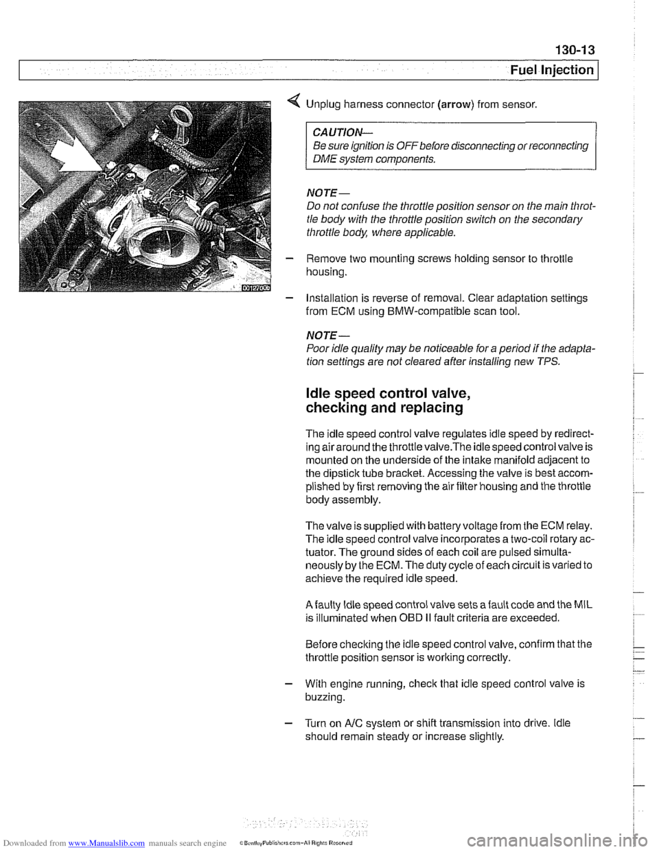
< Unplug harness connector (arrow) from sensor.
CAUTION-
Be sure ignition is OFF before disconnecting or reconnecting
DME system components.
NOTE-
Do not confuse the throttle position sensor on the main Nirot-
tle body with the throttle position switch on the secondary
throttle body, where applicable.
- Remove two mounting screws holding sensor to throttle
housing.
- Installation is reverse of removal. Clear adaptation settings
from ECM using BMW-compatible scan tool.
NOTE-
Poor idle quality may be noticeable for a period if the adapta-
tion settings are not cleared after installing new TPS.
ldle speed control valve,
checking and replacing
The idle speed control valve regulates idle speed by redirect-
inq airaround the throttlevalve.The idlespeed control valve is
mounted on the underside of the intake manifold adjacent to
the dipstick tube bracket. Accessing the valve is best accom-
plished by first removing the air filter housing and the throttle
body assembly.
The valve issupplied with
batteryvoltagefrom the ECM relay.
The idle speed control valve incorporates a two-coil rotary ac-
tuator. The ground sides of each coil are pulsed
sirnulta-
neously by the ECM. The duty cycle of each circuit is varied to
achieve the required idle speed.
Afaulty ldle speed control valve sets afault code and the MIL
is illuminated when
OED II fault criteria are exceeded.
Before checking the idle speed control valve, confirm that the
throttle position sensor is working correctly.
- With engine running, check that idle speed control valve is
buzzing.
- Turn on AIC system or shift transmission into drive. ldle
should remain steady or increase slightly.
Page 409 of 1002
Downloaded from www.Manualslib.com manuals search engine
Fuel Injection I
- As an alternative, harness connector housing can be sepa-
rated so that electrical
checlts can be made from backof con-
nector.
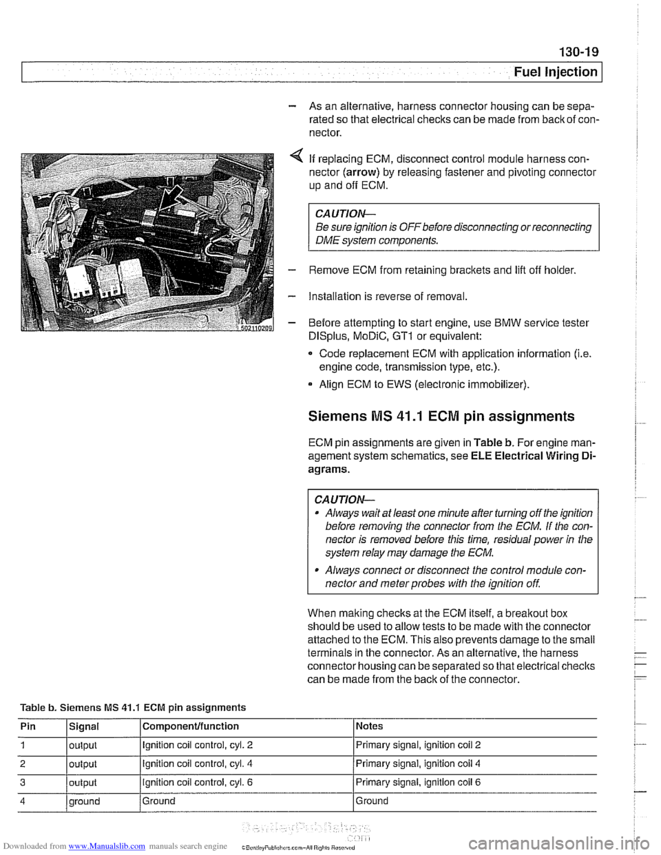
4 If replacing ECM, disconnect control module harness con-
nector (arrow) by releasing fastener and pivoting connector
up and
off ECM.
CAUTION-
Be sure ignition is OFF before disconnecting or reconnecting
DME system components.
- Remove ECM from retaining brackets and lift off holder.
- Installation is reverse of removal.
- Before attempting to start engine, use BMW service tester
DISplus, MoDiC, GTI or equivalent:
- Code replacement ECM with application information (i.e.
engine code, transmission type, etc.).
Align ECM to EWS (electronic immobilizer).
Siemens MS 41.1 ECM pin assignments
ECM pin assignments are given in Table b. For engine man-
agement system schematics, see ELE Electrical Wiring
Di-
agrams.
CAUTION-
a Always wait at least one minute after turning off the ignition
before removing the connector from the
ECM. If the con-
nector is removed before this time, residual power
in the
system relay may damage the
ECM.
Always connect or disconnect the control module con-
nector and meter probes with the ignition
off
When malting checks at the ECM itself, a breakout box
should be used to allow tests to be made with the connector
attached to the ECM. This also prevents damage to the small
terminals in the connector. As an alternative, the harness
connector housing can be separated so that electrical checlts
can be made from the back of the connector.
Table b. Siemens MS
41.1 ECM pin assignments
Pin
1
2
3
4
Signal
output
output
output
qround Componenfffunction
Ignition coil control, cyl. 2
Ignition coil control, cyl. 4
ignition coil control, cyl. 6
Ground Notes
Primary signal,
ignition
coil 2
Primary signal, ignition coil 4
Primary signal, ignition coil 6
Ground
Page 428 of 1002
Downloaded from www.Manualslib.com manuals search engine
130-38
Fuel Injection
Throttle cable, adjusting
(MS 42.0)
The throttle assembly on MS 42.0 cars uses a throttle cable.
The cable should be adjusted any time it is disconnected or
replaced. This procedure requires the factory scan tool or an
equivalent to read and adjust throttle angle. It is recommend-
ed the procedure be done by an authorized
BMW dealer ser-
vice department
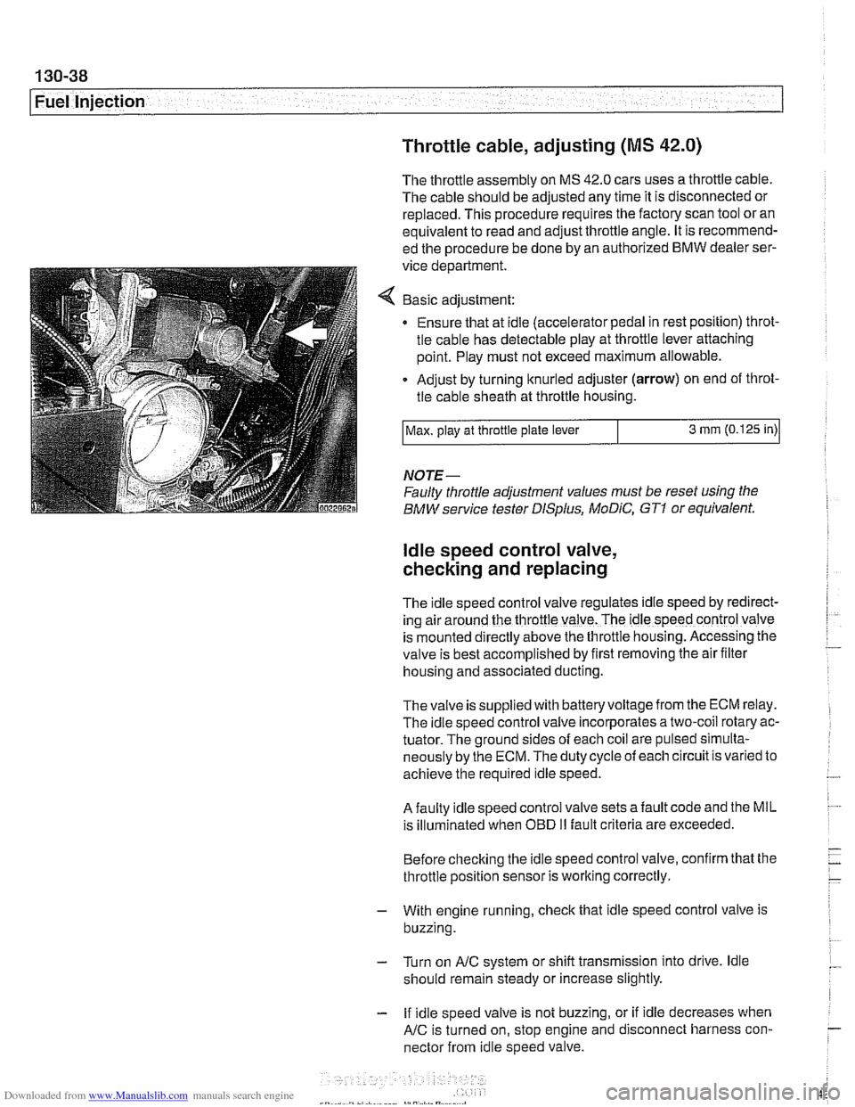
Basic adjustment:
Ensure that at idle (accelerator pedal in rest position) throt-
tle cable has detectable play at throttle lever attaching
point. Play must not exceed maximum allowable.
Adjust by turning knurled adjuster
(arrow) on end of throt-
tle cable sheath at throttle housing.
NOTE-
Faulty throttle adjustment values must be reset using the
BMW service tester
DISplus, MoDiC, GTI or equivalent.
Max.
play at throttle plate lever
ldle speed control valve,
checking and replacing
3 mm (0.125 in)
The Idle speed control valve regulates Idle speed by red~rect-
ing air around the throttle valve. The ldle speed control valve
is mounted
d~rectly above the throttle housing. Accessing the
valve is best accomplished by
flrst removing the air fllter
housing and associated ducting.
Thevalve is supplied with batteryvoltage from the ECM relay.
The idle speed control valve incorporates a two-coil rotary ac-
tuator. The ground sides of each coil are pulsed simulta-
neously by the ECM. The duty cycle of each circuit is varied to
achieve the required idle speed.
A faulty idle speed control valve sets a fault code and the MIL
is illuminated when
OED II fault criteria are exceeded.
Before checking the idle speed control valve, confirm that the
throttle position sensor is working correctly.
- With engine running, check that idle speed control valve is
buzzing.
- Turn on AIC system or shift transmission into drive. ldle
should remain steady or increase slightly.
- If idle speed valve is not buzzing, or if idle decreases when
AIC is turned on, stop engine and disconnect harness con-
nector from idle speed valve.
Page 502 of 1002
Downloaded from www.Manualslib.com manuals search engine
.. - -
I Radiator and Cooling System
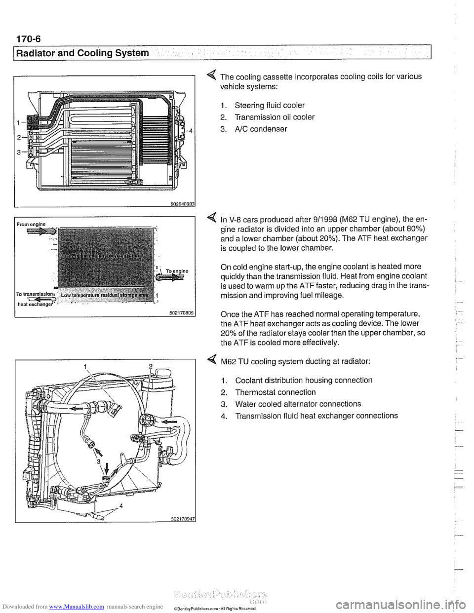
I I 4 The cooling cassette incorporates cooling coils for various
vehicle systems:
1. Steering fluid cooler
2. Transmission oil
coolel
3. AIC condenser
4 In V-8 cars produced after 911998 (M62 TU engine), the en-
gine radiator is divided into an upper chamber (about 80%)
and a lower chamber (about 20%). The ATF heat exchanger
is coupled to the lower chamber.
On cold engine start-up, the engine coolant is heated more
quicltly than the transmission fluid. Heat from engine coolant
is used to warm up the ATF faster, reducing drag in the trans-
mission and improving fuel mileage.
Once the ATF has reached normal operating temperature,
the ATF heat exchanger acts as cooling device. The lower
20% of the radiator
stays cooler than the upper chamber, so
the ATF is cooled more effectively.
4 M62 TU cooling system ducting at radiator:
1. Coolant distribution housing connection
2. Thermostat connection
3. Water cooled alternator connections
4. Transmission fluid heat exchanger connections
Page 542 of 1002
Downloaded from www.Manualslib.com manuals search engine
The lubricant used varies, depending on transmission and
model year. Fluid application information is clearly marked on
a label on transmission.
On manual transmission, either ATF (orange label reads
ATF-Oil) or a special BMW lubricant (yellow label reads MTF-
LT
I) is used. See 230 Manual Transmission.
Automatic transmission is filled with either Dexron
Ill ATF
(black transmission ID plate reads ATF-Oil), or special life-
time oil (green transmission ID plate reads Life-Time Oil). See
240 Automatic Transmission.
CAUTION--
If in doubt as to the type of fluid installed in a particular trans-
mission, consult an authorized
BMW dealer service depari-
ment for the latest in operating fluids.
Page 547 of 1002
Downloaded from www.Manualslib.com manuals search engine
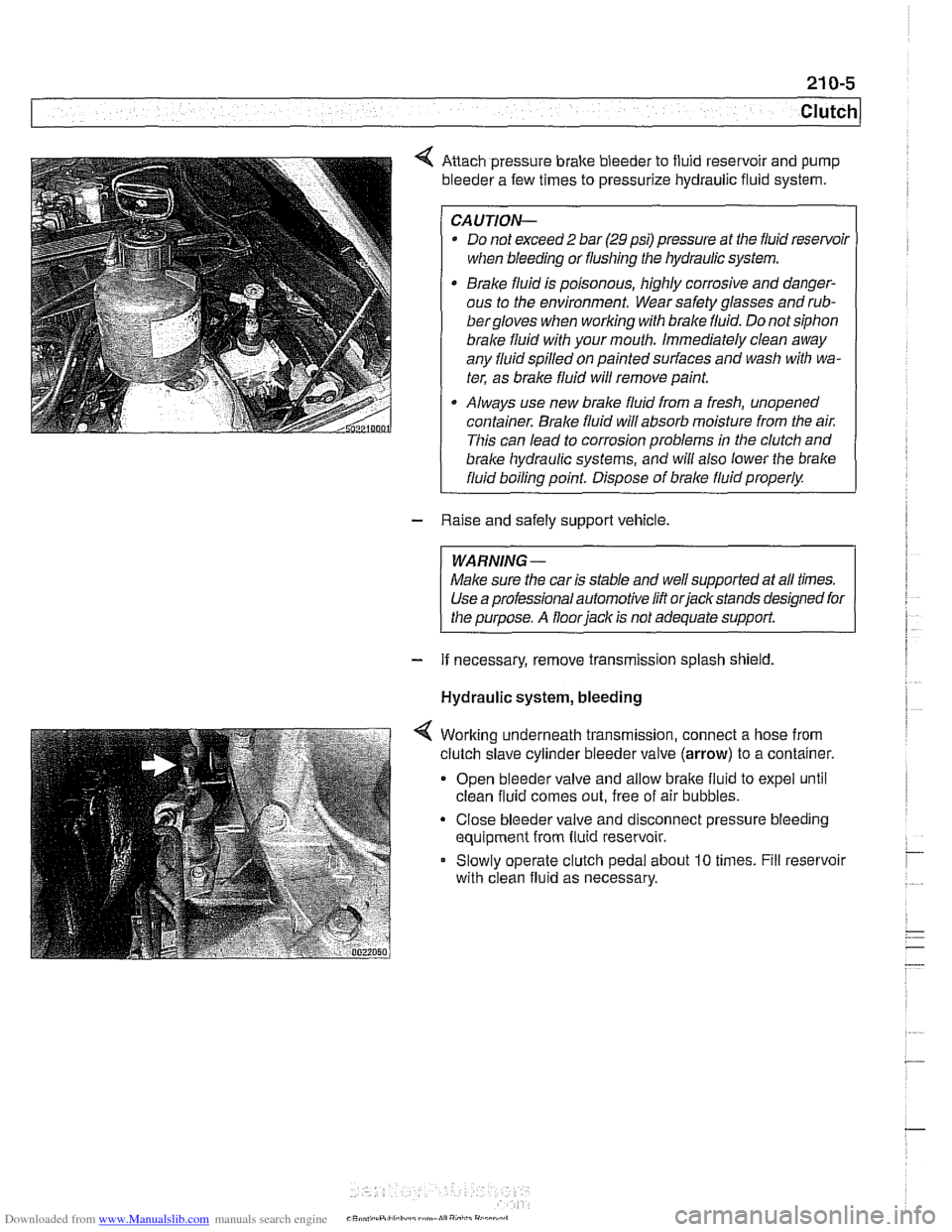
Anach pressure brake bleeder to fluid reservoir and pump
bleeder a few times to pressurize hydraulic fluid system.
CAUTION-
* Do not exceed 2 bar (29 psi) pressure at the fluid resenfoil
when bleeding or flushing the hydraulic system.
Brake fluid is poisonous, highly corrosive and danger-
ous to the environment. Wear safety glasses and
rub-
bergloves when working with brake fluid. Do not siphon
brale fluid with your mouth. Immediately clean away
any fluid spilled on painted surfaces and wash with wa-
ter, as brale fluid will remove paint.
Always use new brake fluid from a fresh, unopened
container.
Brake fluid will absorb moisture from the air.
This can lead to corrosion problems in the clutch and
brake hydraulic systems, ;nd will also lower the brake
fluid boiling point. Dispose of brale fluid properly.
- Raise and safely support vehicle.
WARNING-
Make sure the car is stable and well supported at all times.
Use a professional automotive lift orjackstands designed for
the purpose. A floor
iack is not adequate support.
- If necessary, remove transmission splash shield.
Hydraulic system, bleeding
Worlting underneath transmission, connect a hose from
clutch slave cylinder bleeder valve
(arrow) to a container.
Open bleeder valve and allow bralte fluid to expel until
clean fluid comes out, free of air bubbles.
Close bleeder valve and disconnect pressure bleeding
equipment from fluid reservoir.
Slowly operate clutch pedal about
10 times. Fill reservoir
with clean fluid as necessary.
CR* .,,, .rP,ll,h.:I,,~,~mn.lI","i,,i"
Page 551 of 1002
Downloaded from www.Manualslib.com manuals search engine
- Raise and safely support vehicle
WARNING-
Make sure the car is stable and well supporied at all times.
Use a professional automotive /iff orjack stands designed for
the
ournose. A floor jack is not adeouate suooort.
- If necessary, remove transmission splash shield.
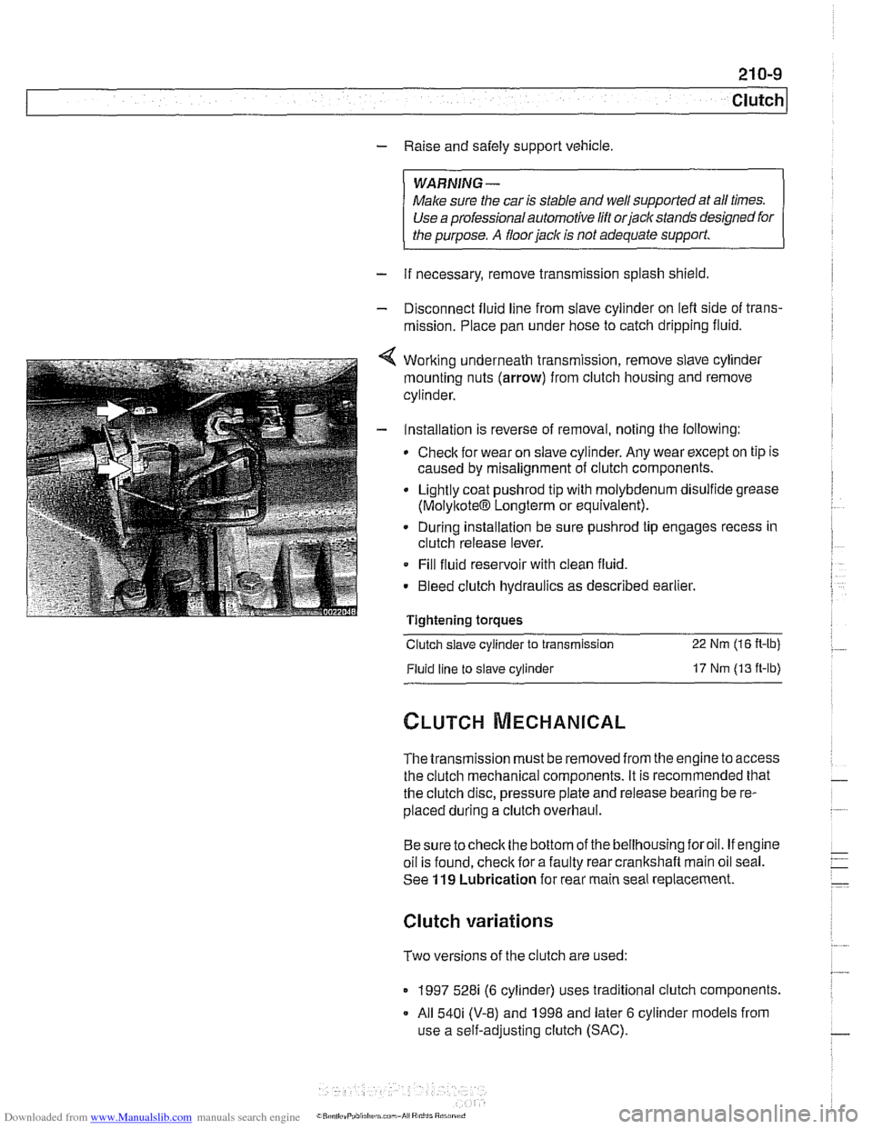
- Disconnect fluid line from slave cylinder on lefl side of trans-
mission. Place pan under hose to catch dripping fluid.
4 Working underneath transmission, remove slave cylinder
mounting nuts (arrow) from clutch housing and remove
cylinder.
- Installation is reverse of removal, noting the following:
Check for wear on slave cylinder. Any wear except on tip is
caused by misalignment of clutch components.
Lightly coat
pushrod tip with molybdenum disulfide grease
(MolyltoteIB Longterm or equivalent).
. During installation be sure pushrod tip engages recess in
clutch release lever.
Fill fluid reservoir with clean fluid.
. Bleed clutch hydraulics as described earlier.
Tightening
toraues - -.
Clutch slave cylinder to transmission 22 Nm (16 R-lb)
Fluid line to slave cylinder 17 Nm (13 ft-lb)
The transmission must be removed from the engine to access
the clutch mechanical components. It is recommended that
the clutch disc, pressure plate and release bearing be re-
placed during a clutch overhaul.
Besure tocheck the bottom of the bellhousing foroil. If engine
oil is found, check for a faulty rear crankshaft main oil seal.
See
119 Lubrication for rear main seal replacement.
Clutch variations
Two versions of the clutch are used:
1997 528i (6 cylinder) uses traditional clutch components.
All
540i (V-8) and 1998 and later 6 cylinder models from
use a self-adjusting clutch (SAC).