Obd BMW 540i 1998 E39 Service Manual
[x] Cancel search | Manufacturer: BMW, Model Year: 1998, Model line: 540i, Model: BMW 540i 1998 E39Pages: 1002
Page 968 of 1002
Downloaded from www.Manualslib.com manuals search engine
OBD-8
I On-Board Diagnostics
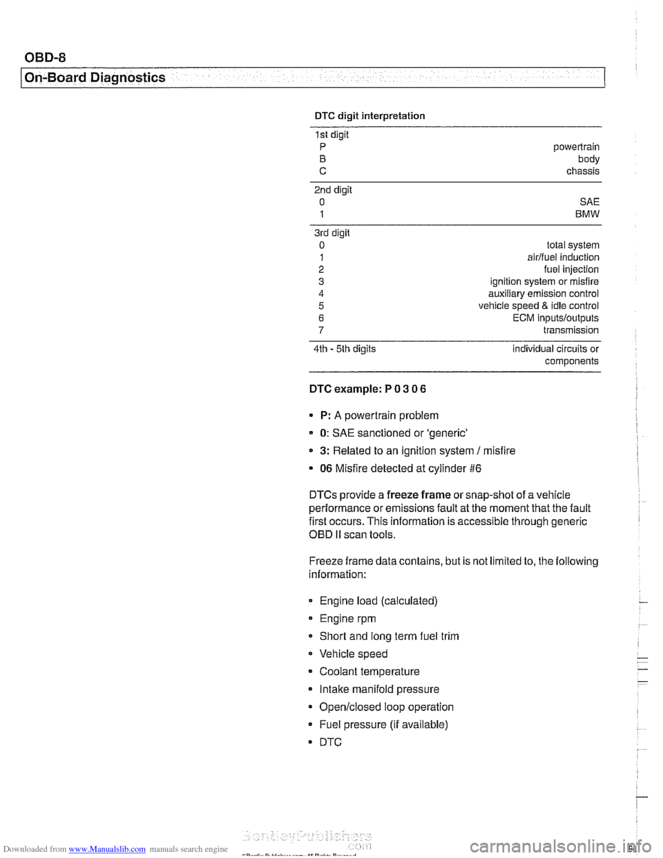
DTC digit interpretation
1st digit
P powertrain
B body
C chassis
2nd digit
0 SAE
1 BMW
3rd digit
0
1
2
3
4
5
6
7
4th - 5th digits total
system
airlfuei induction
fuel injection
ignition system or misfire
auxiliary emission control
vehicle speed
& idle control
ECM
inputs/outputs
transmission
individual circuits or
components
DTC example: P 0 3 0 6
P: A powertrain problem
0: SAE sanctioned or 'generic'
a 3: Related to an ignition system / misfire
06 Misfire detected at cylinder #6
DTCs provide a freeze frame or snap-shot of a vehicle
performance or emissions fault at the moment that the fault
first occurs. This information is accessible through generic
OED I1 scan tools.
Freeze frame data contains, but is not limited to, the following
information:
Engine load (calculated)
Engine rpm
Short and
long term fuel trim
Vehicle speed
Coolant temperature Intake manifold pressure
Open/closed loop operation
Fuel pressure (if available)
DTC
Page 971 of 1002
Downloaded from www.Manualslib.com manuals search engine
OBD-11
On-Board Diagnostics
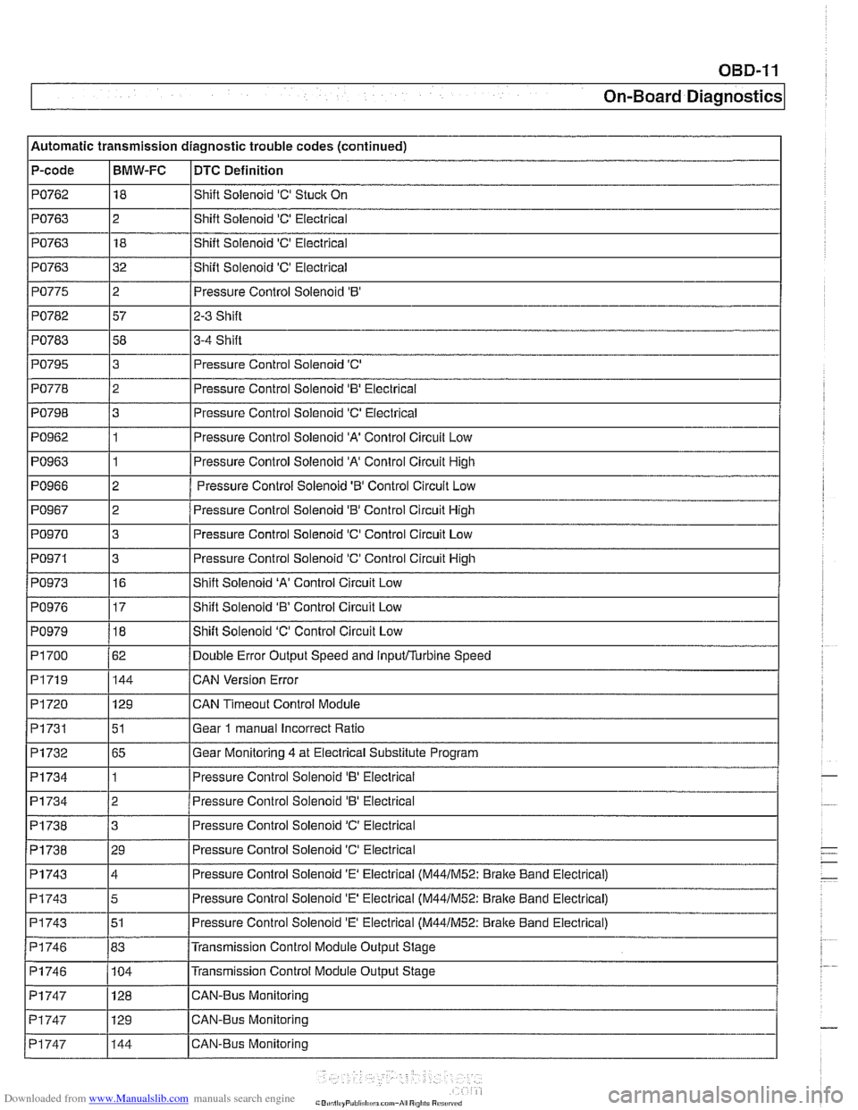
Automatic transmission diagnostic trouble codes (continued)
P-code
PO762
PO763
PO763
PO763
PO775
PO782
PO783 I I
PO795
PO798
PO962
PO963
PO966
PO967
PO970
PO971
BMW-FC
18
2 18
32
2
57
58
I I -
DTC Definition
Shift Solenoid 'C' Stuck On
Shift Solenoid
'C' Electrical
Shift Solenoid
'C' Electrical
Shift Solenoid
'C' Electrical
Pressure Control Solenoid
'B'
2-3 Shift
3-4 Shift
PO778 12 I Pressure Control Solenoid 'B' Electrical
3
3
1
1
2
2
3
3
PO973
PO979
PI 700
PI719
PI720
Pi731
PI732
PI734
Pressure Control Solenoid 'C'
Pressure Control Solenoid
'C' Electrical
Pressure Control Solenoid
'A' Control Circuit Low
Pressure Control Solenoid 'A' Control Circuit High
Pressure Control Solenoid
'6' Control Circuit Low
Pressure Control Solenoid
'0' Control Circuit High
Pressure Control Solenoid 'C' Control Circuit Low
Pressure Control Solenoid 'C' Control Circuit
High
PI734
PI738
Pi738
PO976 117 IShift Solenoid 'B' Control Circuit Low
16
18
62 144
129
51
65
1
PI743
PI743
PI743
PI746
PI746 - Pi747
Shift Solenoid 'A' Control Circuit Low
Shift Solenoid 'C' Control Circuit Low
Double Error Output Speed and
inputflurbine Speed
CAN Version Error
CAN
Timeout Control Module
Gear
1 manual Incorrect Ratio
Gear Monitoring 4 at Electrical Substitute Program
Pressure
Control Solenoid 'B' Eieclrical
2
3
29
PI747
PI747
Pressure Control Solenoid 'B' Electrical
Pressure Control Solenoid
'C' Electrical
Pressure Control Solenoid
'C' Electrical
4
5
51
83 104 Pressure Control Solenoid
'E' Electrical (M44lM52: Brake
Band Electrical)
Pressure Control Solenoid
'E' Electrical (M44lM52: Bralte Band Electrical)
Pressure Control Solenoid
'E' Electrical (M44lM52: Brake Band Electrical)
Transmission Control Module Output Stage
Transmission Control Module Output Stage
129 128 CAN-Bus Monitoring CAN-Bus Monitoring
144 CAN-Bus Monitoring
Page 972 of 1002
Downloaded from www.Manualslib.com manuals search engine
OBD-12
On-Board Diagnostics
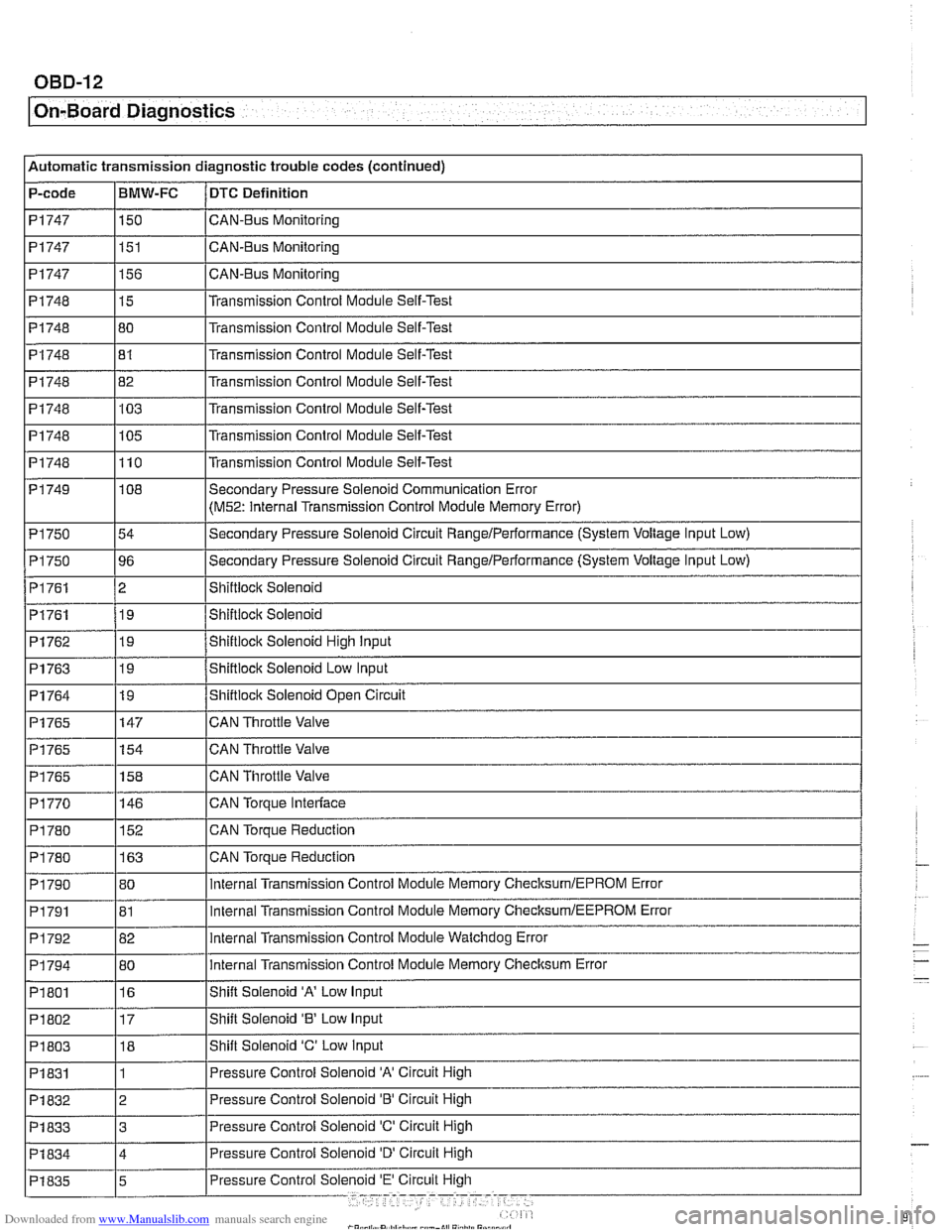
Automatic transmission diagnostic trouble codes (continued)
P-code
PI747
PI747
PI 747
PI748
PI748 I I
PI748
PI748
PI748
PI 748
PI 749
PI 750
P1750
PI761
PI761
BMW-FC
150
151
156
15
80
-- PI762
PI763
PI764
PI765
PI765
PI765
P1770
DTC Definition
CAN-BUS Monitoring
CAN-Bus Monitoring
CAN-Bus Monitoring
Transmission Control Module Self-Test
Transmission
Control Module Self-Test
PI748 182 l~ransmission Control Module Self-Test
81
103
105
110
I I
Transmission Control Module Self-Test
Transmission Control Module Self-Test
Transmission Control Module Self-Test
Transmission Control Module Self-Test
19
19
19
147
154
158
146
PI 790
PI791
P1792
PI 794
PI 801
P1802
PI 803
PI 831 Shiftiock Solenoid High input
Shiftlock Solenoid
Low Input
Shiftlock Solenoid Open Circuit
CAN Throttle Valve
CAN Throttle Valve
CAN Throttle Valve
CAN
Torpue Interlace
CAN Torque Reduction
PI 780
I I -
108
54
96
2 19
PI 780 1163 ICAN Torque Reduction
152
80
81
82
80
16
17 18
1 Secondary Pressure Solenoid Communication Error
(M52: Internal
Transmission Control Module Memory Error)
Secondary Pressure Solenoid Circuit
Rangelperformance (System Voltage Input Low)
Secondary Pressure Solenoid Circuit
RangeIPerformance (System Voltage Input Low)
Shiftioclc Solenoid
Shiftiocic Solenoid
internal Transmission Control Module Memory ChecksumlEPROM Error
internal Transmission Control Module Memory
ChecksumIEEPROM Error
internal Transmission Control Module Watchdog Error
internal Transmission Control Module Memory Checksum Error
Shift Solenoid
'A' Low Input
Shift Solenoid
'8' Low Input
Shift Solenoid
'C' Low input
Pressure Control Solenoid
'A' Circuit High
Pressure Control Solenoid 'B' Circuit High
PI832
PI833 13 IPressure Control Solenoid 'C' Circuit High
2
Page 974 of 1002
Downloaded from www.Manualslib.com manuals search engine
OBD-14
I On-Board Diagnostics
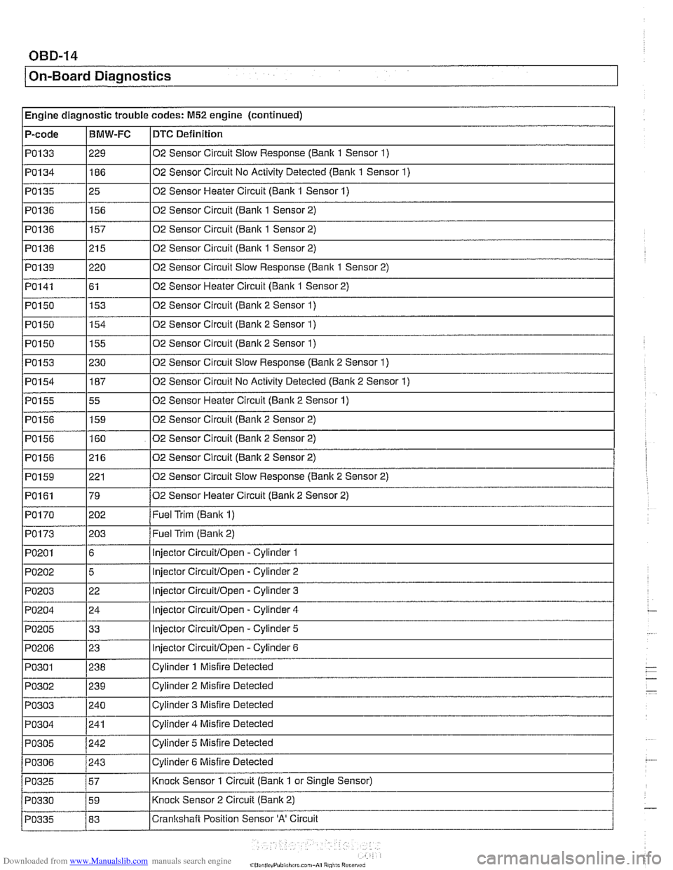
I Engine diagnostic trouble codes: M52 engine (continued) - - -
P-code IBMW-FC ~DTC Definition
PO133
PO134
PO135
PO136
PO136
PO136
PO139
PO141
I I
PO150 1155 102 Sensor Circuit (Bank 2 Sensor 1)
I
I
229
186
25
156
157
215
220 61
PO150 02
Sensor Circuit
Slow Response (Banlc 1 Sensor 1)
02 Sensor Circuit No Activity Detected
(Bank 1 Sensor 1)
02 Sensor Heater Circuit (Bank 1 Sensor 1)
02 Sensor Circuit
(Banlc 1 Sensor 2)
02 Sensor Circuit (Bank 1 Sensor 2)
02 Sensor Circuit (Bank 1 Sensor 2)
02 Sensor Circuit Slow Response
(Bank 1 Sensor 2)
02 Sensor Heater Circuit
(Bank 1 Sensor 2)
PO153
PO154
PO155
PO156
PO156
PO156
PO150 1154 102 Sensor Circuit (Bank 2 Sensor 1)
153
PO159
PO161
PO170
02
Sensor Circuit (Banic 2 Sensor 1)
230
187
55
159
160
21 6
p~-~~--~ PO173
PO201
PO202
PO203
PO204
PO205
PO206
02 Sensor Circuit Slow Response (Banlc 2 Sensor 1)
02 Sensor Circuit No Activity Detected (Bank 2 Sensor
1)
02 Sensor Heater Circuit (Bank 2 Sensor 1)
02 Sensor Circuit (Bank 2 Sensor 2)
02 Sensor Circuit (Banlc 2 Sensor 2)
02 Sensor Circuit (Banlc 2 Sensor 2)
221
79
202 02
Sensor Circuit Slow Response (Banic 2 Sensor 2)
02 Sensor Heater Circuit
(Banic 2 Sensor 2)
Fuel Trim
(Banic 1)
203
6
5
22
24
33
23
Fuel Trim (Banic 2)
injector
Circuitlopen -Cylinder 1
injector
Circuitlopen - Cylinder 2
injector
Circuitlopen -Cylinder 3
Injector
Circuitlopen - Cylinder 4
injector
Circuitlopen - Cylinder 5
lniector
CircuitlOpen - Cvlinder 6
Page 975 of 1002
Downloaded from www.Manualslib.com manuals search engine
OBD-15
On-Board ~iagnosticsl
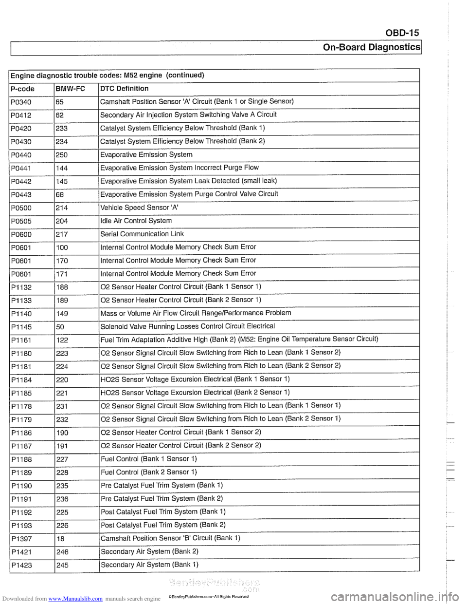
Engine diagnostic trouble codes: M52 engine (continued)
P-code
PO340
PO412
PO420
PO430
PO440
PO441
PO442
PO443
PO500
PO505
PO600
PO601
PO601
I PO601
~1132
~1133
BMW-FC
65
62
233
234
250 144
-
145
68
214
i I
DTC Definition
Camshalt Position Sensor 'A' Circuit (Bank 1 or Single Sensor)
Secondary Air Injection System Switching Valve A Circuit
Catalyst System Efficiency Below Threshold
(Bank 1)
Catalyst System Efficiency Below Threshold (Bank 2)
Evaporative Emission System
Eva~orative Emission Svstem Incorrect Purge Flow .
Evaporative Emission System Leak Detected (small leak)
Evaporative Emission System Purge Control Valve Circuit
Vehicle Speed Sensor 'A'
204
21 7
100
170
171
188
189
PI161
PI180
PI181
PI184
PI185
PI178
02 Sensor Heater Control Circuit (Bank 2 Sensor 2) I
idle Air Control System
Serial Communication
Link
Internal Control Module Memory Check Sum Error
Internal Control Module Memory
Check Sum Error
Internal Control Module Memory
Check Sum Error
02 Sensor Heater Control Circuit (Bank 1 Sensor
1)
02 Sensor Heater Control Circuit (Bank 2 Sensor 1)
Mass or Volume Air Flow Circuit RangeIPerlormance Problem PI140
I
I I
P1188 1227 I Fuel Control (Bank 1 Sensor 1)
PI145 150 /Solenoid Valve Running Losses Control Circuit Electrical
149
122
223
224
220 221
231
I I
P1189 1228 I Fuel Control (Banlc 2 Sensor 1)
Fuel Trim Adaptation Additive High (Bank 2) (M52: Engine Oil Temperature Sensor Circuit)
02 Sensor Signal Circuit Slow Switching from Rich to Lean
(Bank 1 Sensor 2)
02 Sensor Signal Circuit Slow Switching from Rich to Lean
(Bank 2 Sensor 2)
H02S Sensor Voltage Excursion Electrical (Banlc 1 Sensor 1)
HO2S Sensor Voltage Excursion Electrical (Banlc 2 Sensor 1)
02 Sensor Sianai Circuit Slow Switchina from Rich to Lean (Bank 1 Sensor 1)
02 Sensor Signal Circuit Slow Switching from Rich to Lean (Bank 2 Sensor 1) PI179
I I
PI190 1235 I Pre Catalyst Fuel Trim System (Banlc 1)
PI186 1190 102 Sensor Heater Control Circuit (Banlc 1 Sensor 2)
232
I I
PI191 1236 I Pre
Catalyst Fuel Trim System (Banlc 2)
PI192
. . -- - i Pi193 1226 I Post Catalvst Fuel Trim Svstem (Bank 2)
225
PI397
I I
Post Catalyst Fuel Trim System (Bank 1)
PI421 1246 /Secondarv Air System (Bank 2)
18
Secondary Air System (Bank
1) PI423
Camshaft Position Sensor '0' Circuit (Bank 1)
I 245
Page 981 of 1002
Downloaded from www.Manualslib.com manuals search engine
OBD-21
On-Board
~ia~nosticsl
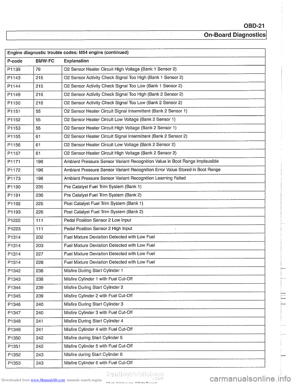
Engine diagnostic trouble codes: M54 engine (continued)
P-code
BMW-FC Explanation
I I
PI314 / 202 / Fuel Mixture Deviation Detected with Low Fuel
I I
02 Sensor Heater Circuit High Voltage (Bank 1 Sensor 2)
02 Sensor Activity Check Signal Too High (Banlc 1 Sensor 2)
02 Sensor Activity Check Signal Too Low (Bank 1 Sensor 2)
02 Sensor Activity Check Signal Too High (Banlc 2 Sensor 2)
02 Sensor Activity Check Signal Too Low (Bank 2 Sensor 2)
02 Sensor Heater Circuit Signal Intermittent (Bank 2 Sensor
1)
02 Sensor Heater Circuit Low Voltage (Bank 2 Sensor 1)
02 Sensor Heater Circuit High Voltage (Bank 2 Sensor 1)
02 Sensor Heater Circuit Signal Intermittent (Banlc 2 Sensor 2)
02 Sensor Heater Circuit Low Voltage (Bank 2 Sensor 2)
02 Sensor Heater Circuit High Voltage (Bank 2 Sensor 2)
Ambient Pressure Sensor Variant Recognition Value in Boot Range Implausible
Ambient Pressure Sensor Variant Recognition Error Value Stored in Boot Range
Ambient Pressure Sensor Variant Recognition Learning Failed
Pre Catalyst Fuel Trim System (Bank 1)
Pre Catalyst Fuel Trim System (Bank 2)
PI139
PI143
PI144
PI149
PI150
PI151
PI152
PI153
PI155
P1156
PI157
PI171
PI172
PI173
PI 190
PI191
79
21 5
21 5
21 6
21 6
55
55
55
61
61
61 196
196
196
235
236
Pedal Position Sensor 2 Low
Input PI222
-~~~~~~~~~ PI314
PI314
PI314
PI342 - PI343
PI 344
PI192
PI193
PI223 /I11 I Pedal Position Sensor 2 High Input
111
PI 345
PI 346
PI 347
PI348
PI 349
PI350
PI351
PI352
PI353
225 Post Catalyst Fuel Trim System (Bank 1)
226 Post Catalyst Fuel Trim Svstem (Bank 2)
203
227
228
238
238
239 Fuel Mixture Deviation Detected with Low Fuel
Fuel Mixture Deviation Detected with Low Fuel
Fuel Mixture Deviation Detected with Low Fuel
Misfire During Start Cylinder 1
Misfire Cylinder 1 with Fuel Cut-Off
Misfire Durina Start Cylinder 2
239
240
240
241
241
242
242
243
243
-
Misfire Cylinder 2 with Fuel Cut-Off
Misfire During Start Cylinder 3
Misfire Cylinder 3 with Fuel Cut-Off
Misfire During Start Cylinder 4
Misfire Cylinder 4 with Fuel Cut-Off
Misfire during Start Cylinder 5
Misfire Cylinder 5 with Fuel Cut-Off
Misfire during Start Cylinder 6
Misfire Cylinder 6 with Fuel Cut-Off
Page 982 of 1002
Downloaded from www.Manualslib.com manuals search engine
OBD-22
I On-Board Diagnostics
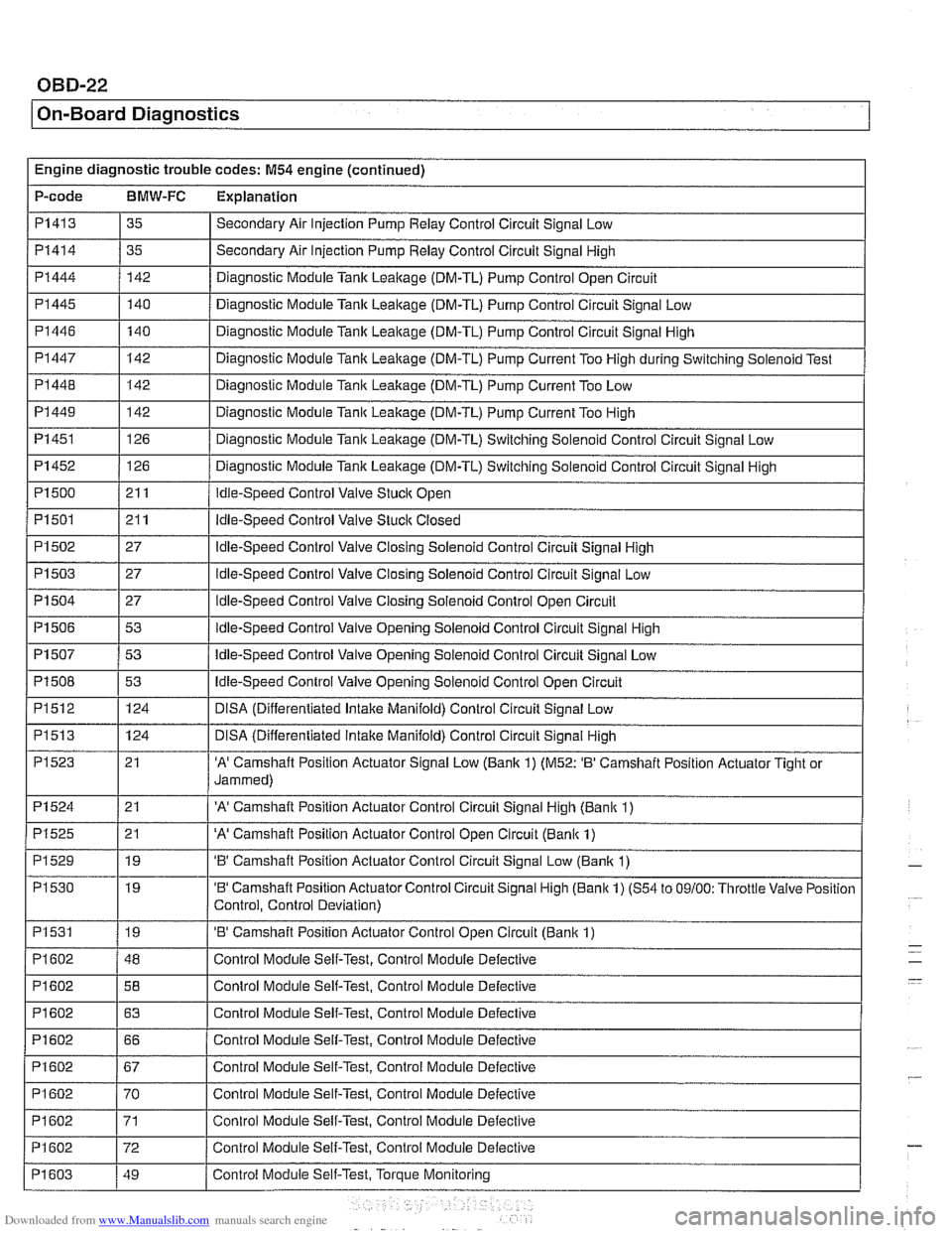
Engine diagnostic trouble codes: M54 engine (continued)
P-code
BMW-FC Explanation
PI 41 3
PI414
PI444
PI 445
PI446
PI447
PI 448
PI 449
PI 451
35
35
142 140
140
142
142
142
126
Secondary Air Injection Pump Relay Control Circuit Signal Low
Secondary Air Injection Pump
Relay Control Circuit Signal High
Diagnostic Module Tank Leakage (DM-TL) Pump Control Open Circuit
Diagnostic Module Tank
Leaitage (DM-TL) Pump Control Circuit Signal Low
Diagnostic Module Tank Lealtage (DM-TL) Pump Control Circuit Signal High
Diagnostic Module
Tanlc Leakage (DM-TL) Pump Current Too High during Switching Solenoid Test
Diagnostic Module
Tank Leakage (DM-TL) Pump Current Too Low
Diagnostic Module
Tank Leakage (DM-TL) Pump Current Too High
Diagnostic Module
Tank Leaitage (DM-TL) Switching Solenoid Control Circuit Signal Low
Page 983 of 1002
![BMW 540i 1998 E39 Service Manual Downloaded from www.Manualslib.com manuals search engine
OBD-23
On-Board ~iagnostics]
I I
PI625 / 147 I Pedal Position Sensor Potentiometer Supply Channel 2 Electrical 1
Engine diagnostic troubl BMW 540i 1998 E39 Service Manual Downloaded from www.Manualslib.com manuals search engine
OBD-23
On-Board ~iagnostics]
I I
PI625 / 147 I Pedal Position Sensor Potentiometer Supply Channel 2 Electrical 1
Engine diagnostic troubl](/img/1/2822/w960_2822-982.png)
Downloaded from www.Manualslib.com manuals search engine
OBD-23
On-Board ~iagnostics]
I I
PI625 / 147 I Pedal Position Sensor Potentiometer Supply Channel 2 Electrical 1
Engine diagnostic trouble codes: M54 engine (continued)
P-code
BMW-FC Explanation
PI 604
PI604
PI619
PI620
PI624
PI632
PI633
PI634
P1 634
PI 634
PI 635
PI 636 50
51 123
123
146 i I
I
I Barometric Pressure Circuit Low
Control
Module Self-Test,
Speed Monitoring
Control Module Self-Test, Speed Monitoring
Map Cooling Thermostat Control Circuit Signal Low
Map Cooling Thermostat Control Circuit Signal High Pedal Position Sensor Potentiometer Supply Channel
1 Electrical (M52: Coolant Thermostat (Coolant
Temperature Below Thermostat Regulating Temperature))
115
115
115
135
136
115
109
PI639
PI675
PI694
P2088
P2089
P2090
P2091
I I
P2229 1197 I Barometric Pressure Circuit High
Throttle
Valve Adaptation Conditions Not Met
Throttle
Valve Adaptation Limp-Home Position Unknown
Throttle Valve Adaptation Spring Test Failed
Throttle
Valve Adaptation Spring Test Failed
Throttle
Valve Adaptation Spring Test Failed
Throttle Valve Adaptation Lower Mechanical Stop not Adapted
Throttle Valve Control Circuit
Throttle Valve Position Control, Control Deviation
PI 637
I I
P2270 1215 1 02 Sensor Signal Stuck Lean (Banic 1 Sensor 2)
PI 638 1160 I Throttle Valve Position Control Throttle Stucic Temporarily
162
161
135
136
21
21 19
19 Throttle
Valve Position Control Throttle
Stucic Permanently
Throttle Valve Actuator Start Test Re-Adaptation Required
Throttle Valve Actuator Start Test Spring Test and Limp-Home Position Failed
'A' Camshaft Position Actuator Control Circuit Low (Banlc 1)
'A' Camshaft Position Actuator Control Circuit High (Banlc 1)
'B' Camshaft Position Actuator Control Circuit Low (Bank 1)
'B' Camshaft Position Actuator Control Circuit High (Bank 1)
P2271
P2272
P2273
P3041
P3198 I I -
215
216
21 6
10481
10205 02
Sensor Signal Stucic Lean (Bank 1 Sensor 2)
02 Sensor Signal
Stuclc Lean (Bank 2 Sensor 2)
02 Sensor Signal Stuclc Lean (Bank 2 Sensor 2)
02 Sensor Lean and Rich Voltage Thresholds not Reached (Bank 2 Sensor 2)
Engine Coolant Temperature Gradient Too High
Engine Coolant Temperature Signal Stuck
P3199
P3238 1 10289 I Control Module Monitoring TPU Chip Defective
10207
Page 988 of 1002
Downloaded from www.Manualslib.com manuals search engine
OBD-28
1 On-Board Diagnostics
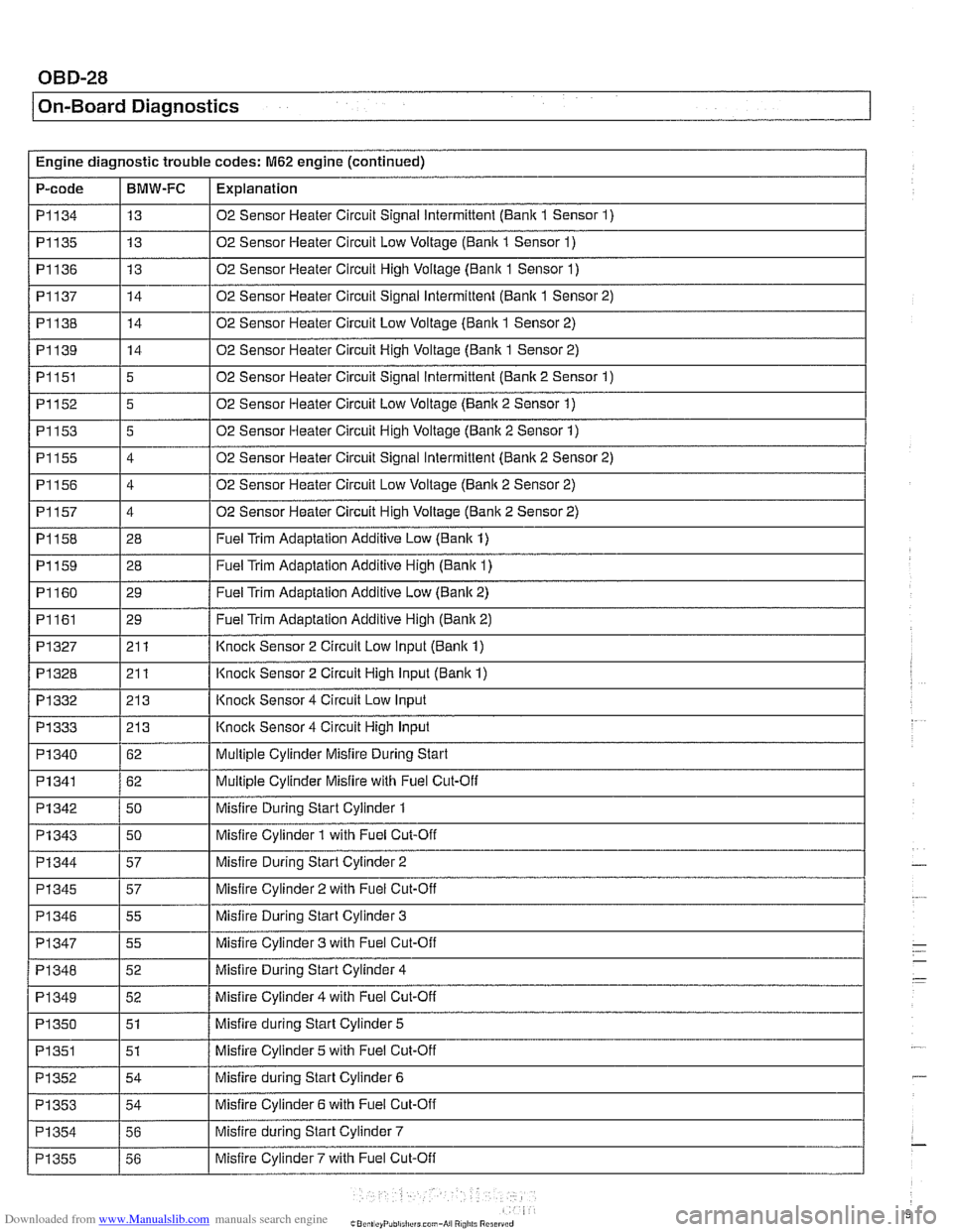
Engine diagnostic trouble codes: M62 engine (continued)
P-code
PI134
PI135
PI136
PI137
PI138 I I . .
PI139
~ PI152
PI153
PI155
PI156
PI157
PI158
PI159
I I
PI 327 1211 / Knoclc Sensor 2 Circuit Low Input (Banlc 1)
BMW-FC
13
13
13
14
14
I I -.
Explanation
02 Sensor Heater Circuit Signal Intermittent (Bank 1 Sensor 1)
02 Sensor Heater Circuit Low Voltage (Bank 1 Sensor 1)
02 Sensor Heater Circuit High Voltage (Bank 1 Sensor 1)
02 Sensor Heater Circuit Signal Intermittent (Bank 1 Sensor 2)
02 Sensor Heater Circuit Low Voltaqe (Bank 1 Sensor 2)
PI151 15 1 02 Sensor Heater Circuit Signal intermittent (Bank 2 Sensor 1)
14
~ 5
5
4
4
4
28
28
PI160
02 Sensor Heater Circuit High Voltage (Bank 1 Sensor 2)
02 Sensor Heater Circuit Low Voltage (Banic 2 Sensor 1)
02 Sensor Heater Circuit High Voltage (Bank 2 Sensor 1)
02 Sensor Heater Circuit Signal Intermittent (Banlc 2 Sensor 2)
02 Sensor Heater Circuit Low Voltage (Bank 2 Sensor 2)
02 Sensor Heater Circuit High Voltage (Bank 2 Sensor 2)
Fuel Trim Adaptation Additive Low (Bank 1)
Fuel Trim Ada~tation Additive Hish (Banlc 1)
PI 328
PI 332
PI 333
PI 340
PI341
PI342
PI343
I
I Misfire During Start Cylinder 3 1
PI161 129 / Fuel Trim Adaptation Additive High (Bank 2)
29
I I
Fuel Trim
Adaptation Additive Low (Banlc 2)
21 I
21 3
213 62
62
50
50
PI344
Knock Sensor 2 Circuit High input (Bank 1)
Knoclc Sensor 4 Circuit Low Input
Knock Sensor
4 Circuit High Input
Multiple Cylinder Misfire During Start
Multiple Cylinder Misfire with Fuel Cut-Off
Misfire During Start Cylinder
1
Misfire Cvlinder 1 with Fuel Cut-Off
PI 347
PI348
PI349
PI 350
PI351
PI352
PI353
PI345 1 57 I Misfire Cylinder 2 with Fuel Cut-Off
57
I I
Misfire During Start Cylinder 2
55
52
52
51
51
54
54
Misfire Cylinder 3 with Fuel Cut-Off
Misfire During Start Cylinder
4
Misfire Cylinder 4 with Fuel Cut-Off
Misfire during Start Cylinder
5
Misfire Cylinder 5 with Fuel Cut-Off
Misfire during Start Cylinder
6
Misfire Cvlinder 6 with Fuel Cut-OW
Misfire during Start Cylinder
7 PI354
PI355 1 56 I Misfire Cylinder7 with Fuel Cut-Off
56
Page 994 of 1002
Downloaded from www.Manualslib.com manuals search engine
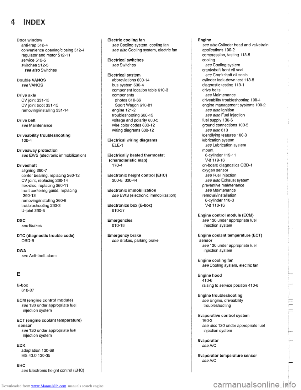
4 INDEX
Door window anti-trap
512-4 convenience openinglclosing 512.4
regulator and motor 512-1 1
service
512-5 switches 512-3
see also Switches
Double
VANOS see VANOS
Drive
axle
CV joint 331-15 CV joint boot 331-15
rernovinglinstalling 331-14
Drive belt
see Maintenance
Driveabiiity troubleshooting
100-4
Driveaway protection
see EWS (eiectronic immobilization)
Driveshaft aligning
260-7
center bearing, replacing 260-12 CV joint, replacing 260-14
itex-disc, replacing 260-1 1
iront centering guide, replacing 260-13
rernovinglinstailing 260-6
lroubleshooting 260-3
U-joint 260-3
DSC
see Braires
DTC (diagnostic trouble code)
OBD-8
DWA
see Anti-theft alarm
ECM (engine control module)
see 130 under appropriate
iuei
injection system
ECT (engine coolant temperature)
sensor see 130 under appropriate
iuei
injection system
EDK adaptation
130-69
MS 43.0 130-35
EHC see Electronic iieigiit control (EHC)
Electric cooling fan
see Cooling system, cooling
fan
see also Cooiing system, eiectric fan
Electrical switches
see Switches
Electrical system abbreviations
600-14 bus System 600-4
component location table 610-3
components
photos
610-36
Sport Wagon 610-81 engine 121-2
troubleshooting 600-15
voltage and polarily 600-5 wire color codes 600-12
wiring diagrams 600-12
Electrical wiring diagrams
ELE-1
Eiectricaliy heated thermostat
(characteristic map)
170-4
Eiectronic height control (EHC)
300-8, 330-44
Eiectronic immobilization
see EWS (electronic immobilization)
Eiectronics box
(E-box)
610-37
Emergencies
010-18
Emergency brake see
BraBes, parking brake Engine
see also Cylinder head and valvetrain
applications
100-2
compression, testing 113-5
cooling see Cooiing system
crankshaft front oil seai
see Crankshaft oil seals
cyiinder leak-down test 113-8
diagnostic testing 113-1
drive belts
see Maintenance
driveability troubleshooting
100-4
engine management systems 100-2
see also Ignition
see also Fuel injection
fuel supply
130-6
ground connections 100-5
see also 61 0 identilying ieatures 100-3
lubrication svstem
see
~ubricetion system
mount
on-board diagnostics
OBD-I
oxygensensor
see Fuel injection
see also Exhaust system
Dreventive maintenance
see Maintenance
removal/installation
Engine control module (ECM)
see 130 under appropriate iuel
injection system
Engine cooiant temperature (ECT)
sensor see 130 under appropriate iuel
injection
system
Engine cooling fan
see Cooiing system, electric fan
Engine hood
41
0-6 raising to service position 410-6
Engine troubleshooting
see Engine, driveability troubleshooting
EVa~oratiVe control svstem
160-3 see also 130 under aDDroDriate iuel
injection system
Evaporator see
NC
Evaporator temperature sensor see
NC