Obd BMW 540i 1998 E39 User Guide
[x] Cancel search | Manufacturer: BMW, Model Year: 1998, Model line: 540i, Model: BMW 540i 1998 E39Pages: 1002
Page 350 of 1002
Downloaded from www.Manualslib.com manuals search engine
Ignition System
This repair group covers component troubleshooting and re-
placement information for the ignition system.
When diagnosing engine management problems, including
on-board diagnostics (OBD
11) fault code analysis, also refer
to these repair groups:
* 130 Fuel Injection
* ELE Electrical Wiring Diagrams
OED On-Board Diagnostics
Special tools
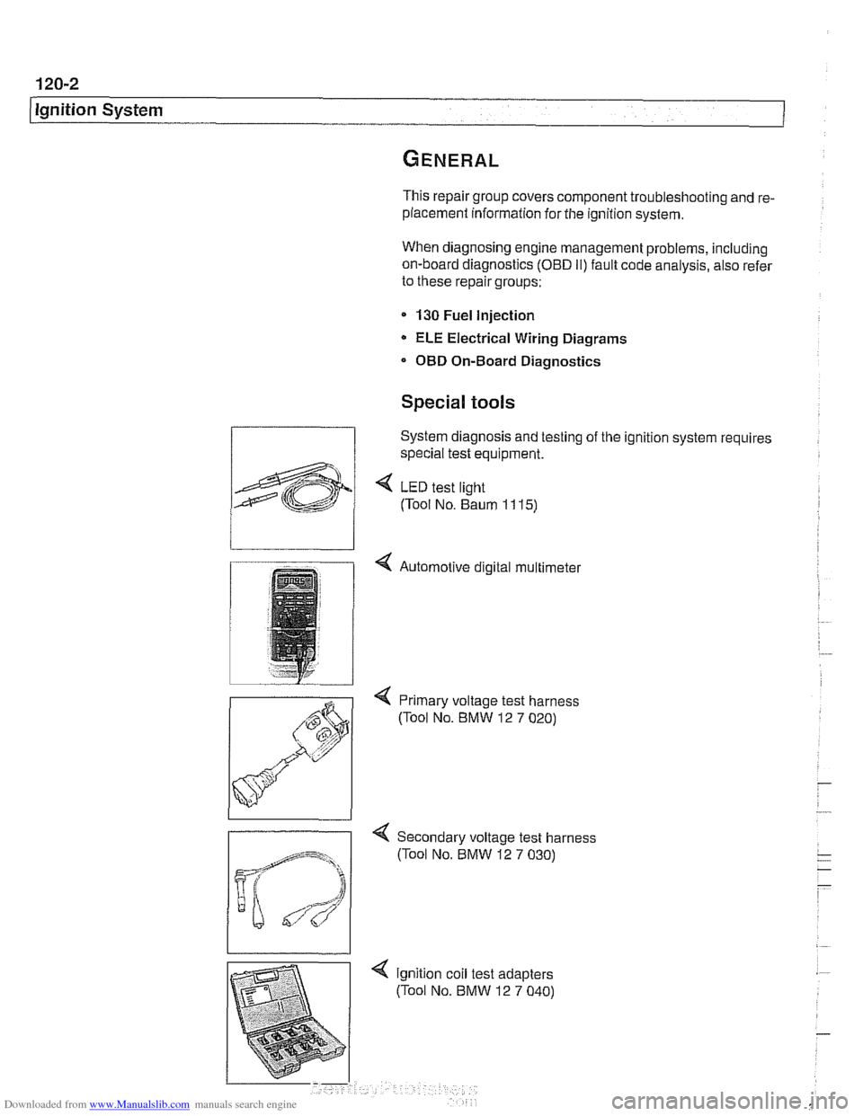
System diagnosis and testing of the ignition system requires
special test equipment.
4 LED test light
(Tool No. Baum
1 1 15)
4 Automotive digital multimeter
4 Primary voltage test harness
(Tool No. BMW 12
7 020)
-
4 Secondary voltage test harness
(Tool No. BMW 12
7 030)
Page 352 of 1002
Downloaded from www.Manualslib.com manuals search engine
I lgnition System
Additional information about DTCs and engine management
system electronic system diagnosis is provided in
OBD On-
Board Diagnostics.
Table a. Engine management systems
Year
l~ngine I Engine type IDME svstem I - I - . . I
Ignition system
1997-1 998
1997
1998
1999-2002
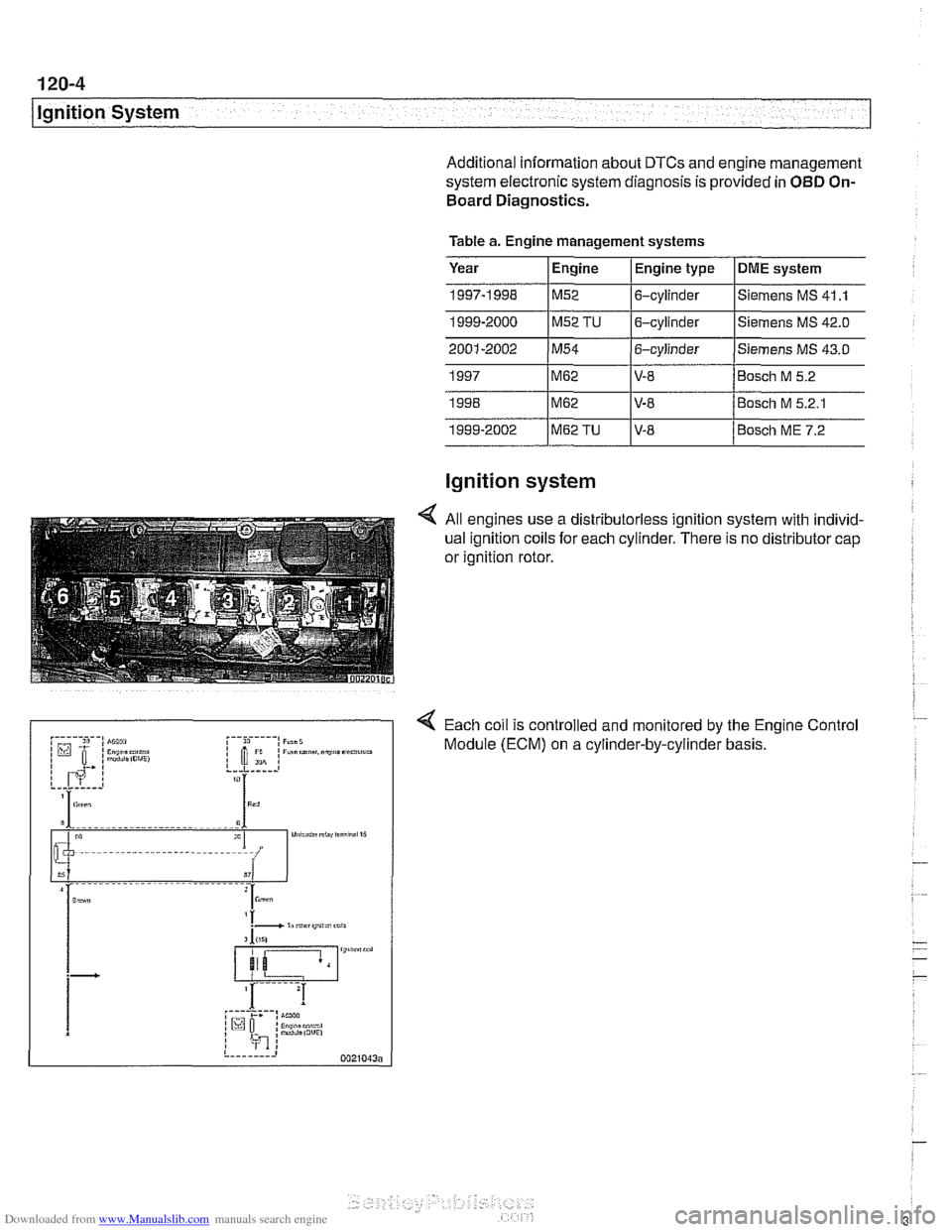
4 All engines use a distributorless ignition system with individ-
ual ignition coils for each cylinder. There is no distributor cap
or ignition rotor.
4 Each coil is controlled and monitored by the Engine Control
Module (ECM) on a cylinder-by-cylinder basis.
1999-2000
1~52 TU 16-cylinder l~iemens MS
42.0
M62
M62
M62TU
Siemens MS 41 .I M52 6-cylinder
V-8
V-8 V-8 Bosch
M 5.2
Bosch M 5.2.1
Bosch ME 7.2
Page 354 of 1002
Downloaded from www.Manualslib.com manuals search engine
120-6
lgnition System
lgnition system, troubleshooting
Troubleshooting ignition system faults should begin with an
interrogation of the On-Board Diagnostics (OBD
II) system.
The OBD
II system detects ignition system misfire and other
related faults. When faults are detected, the OBD
II system
stores a Diagnostic Trouble Code (DTC) in the Engine Con-
trol Module (ECM) along with other pertinent fault information.
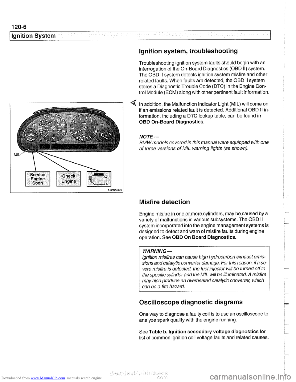
4 In addition, the Malfunction Indicator Light (MIL) will come on
if an emissions related fault is detected. Additional OBD
II in-
formation, including a DTC lookup table, can be found in
OED On-Board Diagnostics.
NOTE-
BMWmodels covered in this manual were equipped with one
of three versions of
MIL warning lights (as shown).
Misfire detection
Engine m~sfire in one or more cylinders, may be caused by a
var~ety of malfunctions in various subsystems. The OBD II
system ~ncorporated into the engine management systems is
des~gned to detect and warn of misfire faults during englne
operat~on. See OED On Board Diagnostics.
WARNING -
lgnition misfires can cause high hydrocarbon exhaust emis-
sions andcatalytic converter damage. For this reason, if a se-
vere misfire is detected, the fuel injector
will be turned off to
the specific cylinder and the
MIL will be illuminated. A misfire
may also produce an overheated catalytic converter, which
can be a fire hazard.
Oscilloscope diagnostic diagrams
One way to diagnose a faulty coil is to use an oscilloscope to
analyze spark quality with the engine running.
See Table b. lgnition secondary voltage diagnostics for
list of common ignition
coil voltage faults and related causes.
Page 360 of 1002
Downloaded from www.Manualslib.com manuals search engine
120-1 2
ignition System
Crankshaftspeedsensor
Crankshaft speed sensor, replacing (M52, M52 TU and
M54 engines)
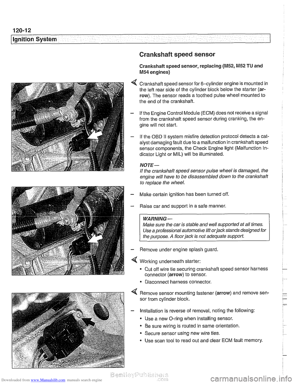
4 Crankshaft speed sensor for 6-cylinder engine is mounted in
the left rear side of the cylinder block below the starter (ar-
row). The sensor reads a toothed pulse wheel mounted to
the end of the crankshaft.
- if the Engine Control Module (ECM) does not receive a signal
from the crankshaft speed sensor during cranking, the en-
gine will not start.
- If the OBD II svstem misfire detection ~rotocol detects a cat- - - ~~
alysr oarnagin; faLlt oJe to a ma I-nclion in crandshafi speeo
sensor components. Ine Check Engine
lignr (Malfuncrion In-
dicator Light or MIL) will be illuminated.
NOTE-
If the crankshaft speed sensor pulse wheel is damaged, the
engine will have to be disassembled down to the crankshaft
to
reolace the wheel.
- Make certain ignition has been turned off.
- Raise car and support in a safe manner.
WARNING -
Make sure the car is stable and well supported at all times.
Use a professional automotive lift orjacltstands designed for
the ouroose.
A floor iaclc is not adequate support.
- Remove under engine splash guard
4 Working underneath starter:
Cut off wire tie securing crankshaft speed sensor harness
connector (arrow) to sensor.
* Disconnect harness connector.
4 Remove sensor mounting fastener (arrow) and remove sen-
sor from cylinder block.
- Installation is reverse of removal, noting the following:
Use a new O-ring when installing sensor.
Be sure wiring is routed in same orientation.
Secure sensor using new wire ties.
Use scan tool to read out and clear ECM fault memory.
Page 361 of 1002
Downloaded from www.Manualslib.com manuals search engine
ignition System
Crankshaft speed sensor, replacing (M62 and M62TU
engines)
The crankshaft speed sensor reads a toothed pulse wheel
mounted on the flywheel.
If the Engine Control Module(ECM)
does not receive an impulse signal from the crankshaft speed
sensor during
cranking, the engine will not start. If the OBD II
system misfire detection protocol detects a catalyst damag-
ing fault due to a malfunction in the crankshaft speed sensor
components, the Check Engine light (Malfunction
Indicator
Light or MIL) will be Illuminated.
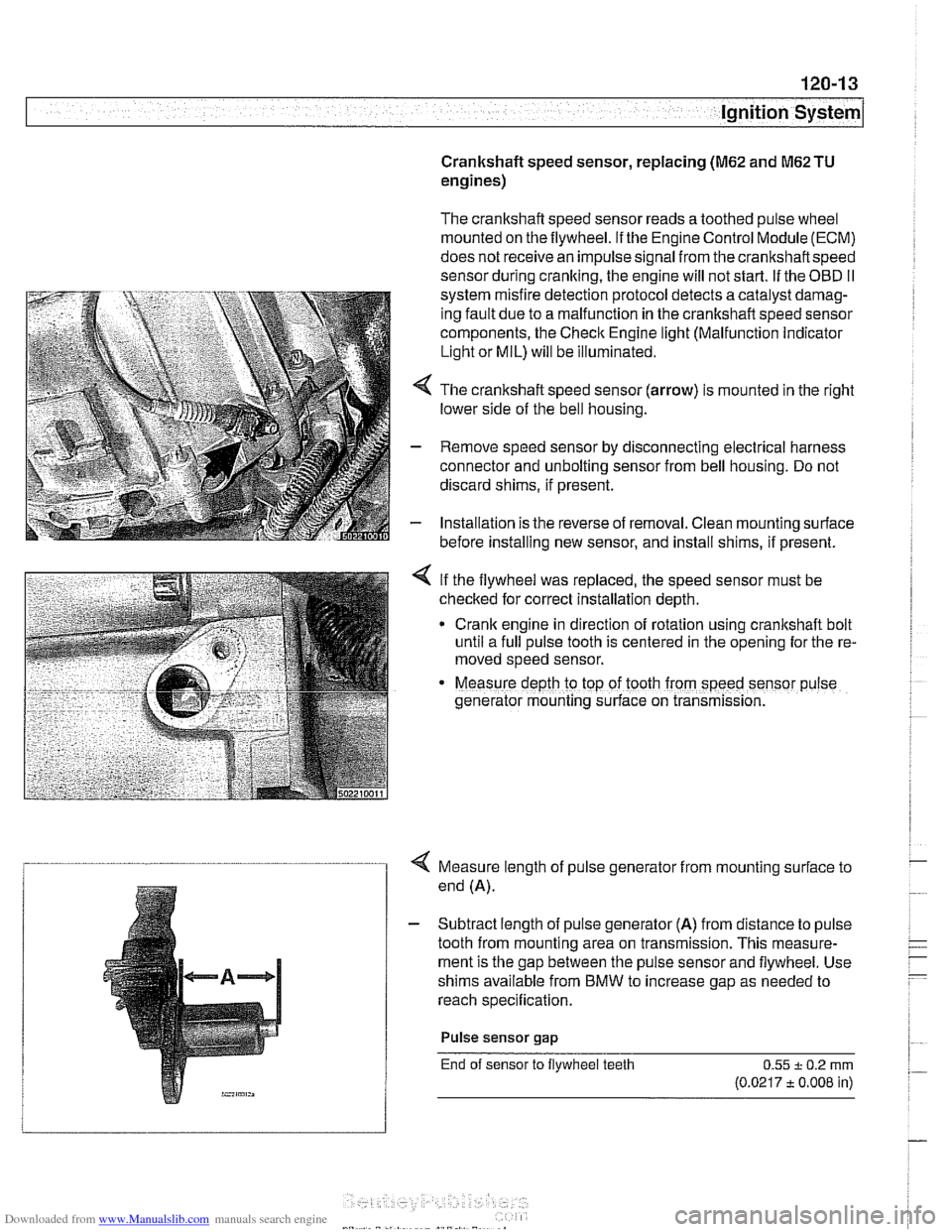
4 The crankshaft speed sensor (arrow) is mounted in the right
lower side of the bell housing.
- Remove speed sensor by disconnecting electrical harness
connector and unbolting sensor from bell housing. Do not
discard shims, if present.
- Installation is the reverse of removal. Clean mounting surface
before installing new sensor, and install shims, if present.
< If the flywheel was replaced, the speed sensor must be
checked for correct installation depth.
* Crank engine in direction of rotation using crankshaft bolt
until a full pulse tooth is centered in the opening for the re-
moved speed sensor.
Measure depth ro top of tooth from speed sensor p~lse
generator mounting s~rface on transmission.
4 Measure length of pulse generator from mounting surface to
end (A).
- Subtract length of pulse generator (A) from distance to pulse
tooth from mounting area on transmission. This measure-
ment is the gap between the pulse sensor and flywheel. Use
shims available from BMW to increase gap as needed to
reach specification.
Pulse sensor
gap
End of sensor to flywheel teeth 0.55 + 0.2 rnrn
(0.0217 t 0.008 in)
Page 392 of 1002
Downloaded from www.Manualslib.com manuals search engine
130-2
/Fuel Injection
This repair group covers service and repair of the Bosch and
Siemens engine management systems used on
1997
through 2002 E39 models. Additional engine management
service and repair information may also be found in the fol-
lowing repair groups:
0 020 Maintenance
120 Ignition System
160 Fuel Tank and Fuel Pump
610 Electrical Component Locations
OBD On Board Diagnostics
NOTE-
Camshaft position sensor, crankshaft speed sensor and
knoclc sensors are covered in 120 Ignition System.
Table a. Engine management system applications
- - ~ ~
1 ~odellmodel year / Engine IDME system I - I
5281, 1997-1 998 IM52. 2.8 liter ISiemens MS 41 .I I 1
528i. 1999ZO00 1~52 TU, 2.8 liter ]siemens MS 42.0 I I
5251, 2001-2002 1~54, 2.5 liter 1 Siemens MS 43.0 I I
530i, 2001-2002 1~54, 3.0 liter ISiemens MS 43.0
5401 1999-2001 1~62 TU, 4.4 liter l~osch ME 7.2
I
OBI) II software and hardware is incorporated in the engine
management control systems. The
OED II system monitors
components that influence exhaust and evaporative emis-
sions. If a problem is detected, the
OED I1 system stores the
associated fault code and condition.
540i. 1997
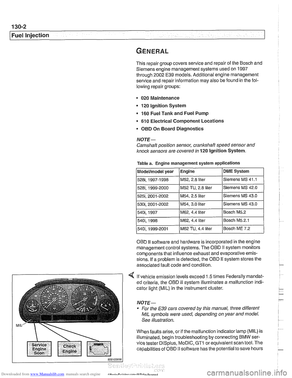
4 If vehicle emission levels exceed 1.5 times Federally mandat-
ed criteria, the
OED II system illuminates a malfunction indi-
cator light
(MIL) in the instrument cluster.
For the
E39 cars covered by this manual, three different
MIL symbols were used, depending on year and model.
See illustration.
When faults arise, or if the malfunction indicator lamp (MIL) is
illuminated, begin troubleshooting by connecting BMW ser-
vice tester
DISplus, MoDiC, GTl or equivalent scan tool. The
capabilities of OBD
II software has the potential to save hours
540i. 1998 IM62, 4.4 liter /Bosch M5.2.1
M62, 4.4 liter Bosch M5.2
Page 393 of 1002
Downloaded from www.Manualslib.com manuals search engine
-
Fuel Injection
of diagnostic time and to help avoid incorrect component re-
placement and possible damage to system components.
NOTE-
* Professional diagnostic scan tools available at the time of
this printing include the BMW factory tools and a small
number of aftermarket BMW-specific tools. The
CS2000
from Baum Tools Unlimited, the Retriever from Assenma-
chef Specialty Tools, and the MT2500 from Snap-on are
three examples.
In addition to the BMW-specific professional line of scan
tools, there are inexpensive generic OBD
I1 scan tool soft-
ware programs and
handheld units available. Although
these tools have limited capabilities as compared to the
dedicated tools, they are powerful diagnostic tools.
For the
DIY owner, simple aftermarltet DTC readeris avail-
able through
http://www.pealteresearch.com. This tool is
capable of checlting for
DTCs as well as turning off the il-
luminated
MIL and resetting the service indicator lights.
Tools and test equipment
If the equipment required to do the job is unavailable, it is rec-
ommended that these repairs be left to an authorized
BMW
dealer or other qualified BMW repair facility.
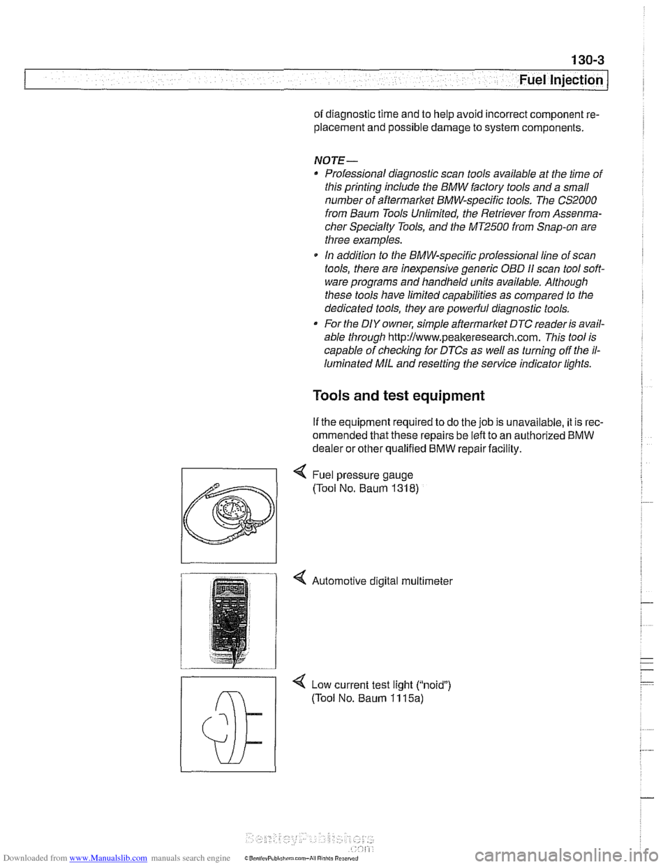
4 Low current test light ("noid")
(Tool No. Baum 11 15a)
Page 396 of 1002
Downloaded from www.Manualslib.com manuals search engine
130-6
Fuel Injection
Fuel supply to the injection system is provided by a high pres-
sure electric pump mounted inside the fuel tank. The pump is
powered via the fuel pump relay. If the relay is faulty, the fuel
pump will not run and the engine will not start.
NOTE-
* Fuel delivery volume and fuel pressure are critical to prop-
er operation. Fuel pressure direcfly influences fuel deliv-
ery
Fuel pump relay, fuel pressure and fuel volume tests are
given in 160 Fuel Tank and Fuel Pump.
Relieving system fuel pressure
The fuel system retains fuel pressure in the system when the
engine is off. To prevent fuel from spraying on a hot engine,
system fuel pressure should be relieved beforedisconnecting
fuel lines. One method is to tightly wrap
ashop towel around a
fuel line fitting and loosen or disconnect the fitting. Cleanli-
ness is essential when working with fuel components. Thor-
oughly clean the unions before disconnecting fuel lines.
When system faults are detected, a diagnostic trouble code
(DTC) is stored in the engine control module (ECM). The MIL
also iiluminates if an emissions-related fault is detected
When faults arise, or if the malfunction indicator lamp (MIL) is
illuminated, begin troubleshooting by connecting BMW ser-
vice tester
DISplus. MoDiC, GTI or equivalent scan tool. The
capabilities of OBD
II software has the potential to save hours
of diagnostic time and to help avoid incorrect component re-
placement and possible damage to system components.
CAUTION-
- The tests in this section may set fault codes (DTCs) in the
ECM and illuminate the
MIL. Affer all testing is completed,
access and clear DJC fault memory using an
OED I1 or
BMW compatible scan tool. See OBD On-Board Diag-
nostics.
0 Only use a digital multimeter for electrical tests.
. Relay positions can vary Be sure to confirm relay posi-
tion by identifying the wiring in the socket using the wir-
ing diagrams found in ELE Electrical Wiring
Diagrams.
Page 397 of 1002
Downloaded from www.Manualslib.com manuals search engine
Fuel Injection 1
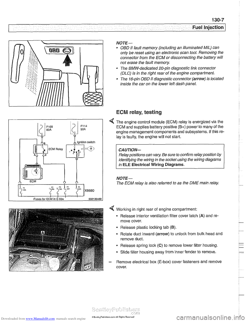
Working in right rear of engine compartment:
Release interior ventilation filter cover latch
(A) and re-
move cover.
Release plastic locking tab
(6).
Rotate duct inward (arrow) to unlock from bulk head and
remove duct.
Release spring
lock (C) to remove lower iilter housing.
Slide filter housing away from inner fender to remove.
- Remove electrical box (E-box) cover fasteners and remove
cover.
NOTE-
OBD I1 fault memory (including an illuminated MIL) can
only be reset using an electronic scan tool. Removing the
connector from the ECM or disconnecting the battery will
not erase the fault
memory.
The BMW-dedicated 20-pin diagnostic linlc connector
(DLC) is in the right rear of the engine compartment.
The 16-pin OBD
I1 diagnostic connector (arrow) is located
inside the car on the lower left dash panel.
ECM relay, testing
Fuses lor ECM In E-bbx 502130488
4 The engine control module (ECM) relay is energized via the
ECM and supplies battery positive
(B+) power to many of the
engine management components and subsystems.
If this re-
lay is faulty, the engine will not start.
Relay positions can vary. Be sure to confirm relay position by
identifying the wiring in the socket using the wiring diagrams
in
ELE Electrical Wiring Diagrams.
NOTE-
The ECM relay is also referred to as the DME main relay.
Page 399 of 1002
Downloaded from www.Manualslib.com manuals search engine
Fuel Injection I
Mass air flow (MAF) sensor,
checking and replacing
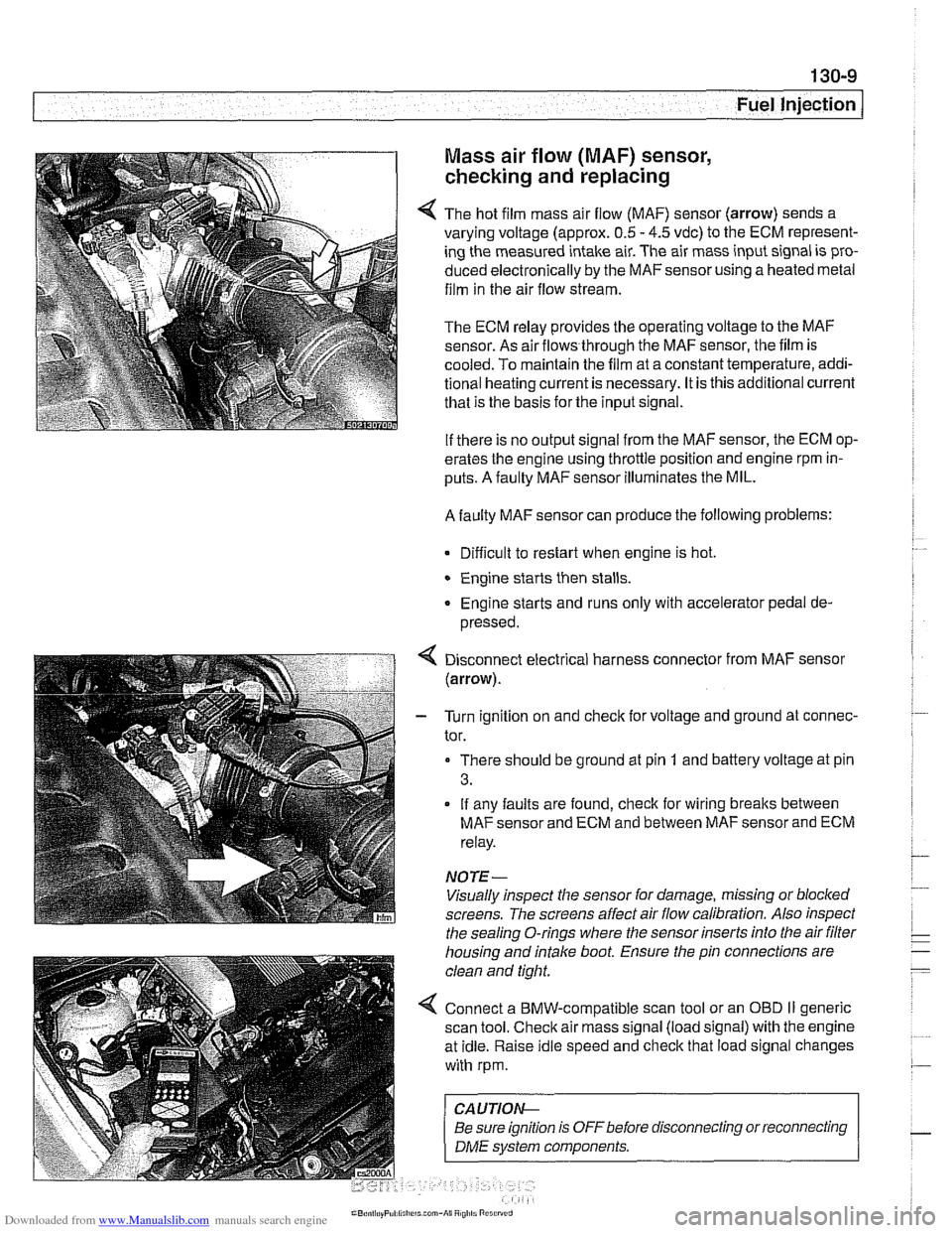
4 The hot film mass air flow (MAF) sensor (arrow) sends a
varying voltage (approx.
0.5 - 4.5 vdc) to the ECM represent-
ing the measured intake air. The air mass input signal is pro-
duced electronically by the
MAFsensorusing a heated metal
film in the air flow stream.
The ECM relay provides the operating voltage to the MAF
sensor. As air flows through the MAF sensor, the film is
-
cooled. To maintain the film at a constant temperature, addi-
tional heating current is necessary. It is this additional current
that is the basis for the input signal.
If there is no output signal from the MAF sensor, the ECM op-
erates the engine using throttle position and engine rpm in-
puts. A faulty MAF sensor illuminates the MIL.
A faulty MAF sensor can produce the following problems:
Difficult to restart when engine is hot.
Engine starts then stalls.
Engine starts and runs only with accelerator pedal de-
pressed.
Disconnect electrical harness connector from MAF sensor
(arrow).
- Turn ignition on and check for voltage and ground at connec-
tor.
There should be ground at pin
1 and battery voltage at pin
3.
If any faults are found, check for wiring breaks between
MAF sensor and ECM and between MAF sensor and ECM
relay.
NOTE-
Visually inspect the sensor for damage, missing or blocked
screens. The screens affect air flow calibration. Also inspect
the sealing O-rings where the sensor inserts into the air
filter
housing and intake boot. Ensure the pin connections are
clean and tight.
4 Connect a BMW-compatible scan tool or an OBD II generic
scan tool. Check air mass signal (load signal) with the engine
at idle. Raise idle speed and check that load signal changes
with rpm.
CA UTIOI\C
Be sure ignition is OFFbefore disconnecting or reconnecting r
1 DME svstem components. 1