relay BMW 540i 1998 E39 Service Manual
[x] Cancel search | Manufacturer: BMW, Model Year: 1998, Model line: 540i, Model: BMW 540i 1998 E39Pages: 1002
Page 460 of 1002
Downloaded from www.Manualslib.com manuals search engine
130-70
Fuel Injection
ECM relay
--
CAUTION-
Relay positions can vary Be sure to confirm relay position by
identifying the wiring in the
socl(et using the wiring diagrams
in ELE Electrical Wiring Diagrams.
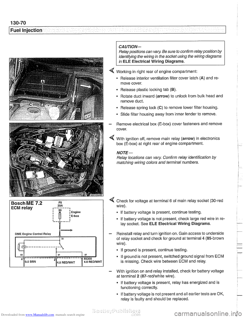
Working in right rear of engine compartment:
Release interior ventilation filter cover latch
(A) and re-
move cover.
Release plastic locking tab
(B).
Rotate duct inward (arrow) to unlock from bulk head and
remove duct.
Release spring
loclt (C) to remove lower filter housing.
Slide filter housing away from inner fender to remove.
- Remove electrical box (E-box) cover fasteners and remove
cover.
4 With ignition off, remove main relay (arrow) in electronics
box (E-box) at right rear of engine compartment.
NOTE-
Relay locations can vary Confirm relay identification by
matching wiring colors and terminal numbers.
4 Check for voltage at terminal 6 of main relay socket (30-red
wire).
If battery voltage is present, continue testing.
If battery voltage is not present, check large red wire in re-
lay socltet. See ELE Electrical Wiring Diagrams.
- Reinstall relay and turn ignition on. Gain access to underside
of relay socket and check for ground at terminal
4 (85-brown
wire).
If ground is present, continue testing.
If ground is not present, switched ground signal from ECM
is missing. Check wire between ECM and relay.
- With ignition on and relay installed, check for battery voltage
at terminal
2 (87-redlwhite wire).
If battery voltage is present, relay has energized and is
functioning correctly.
If battery voltage is not present and all earlier tests are OK.
relay is faulty and should be replaced.
Page 463 of 1002
Downloaded from www.Manualslib.com manuals search engine
( Mass Air Flow Sensor
1" Intake air temp. (NTC)
Sensor qround
Reference voltage . . . -., f fitr mass signal I
Fuel Injection I
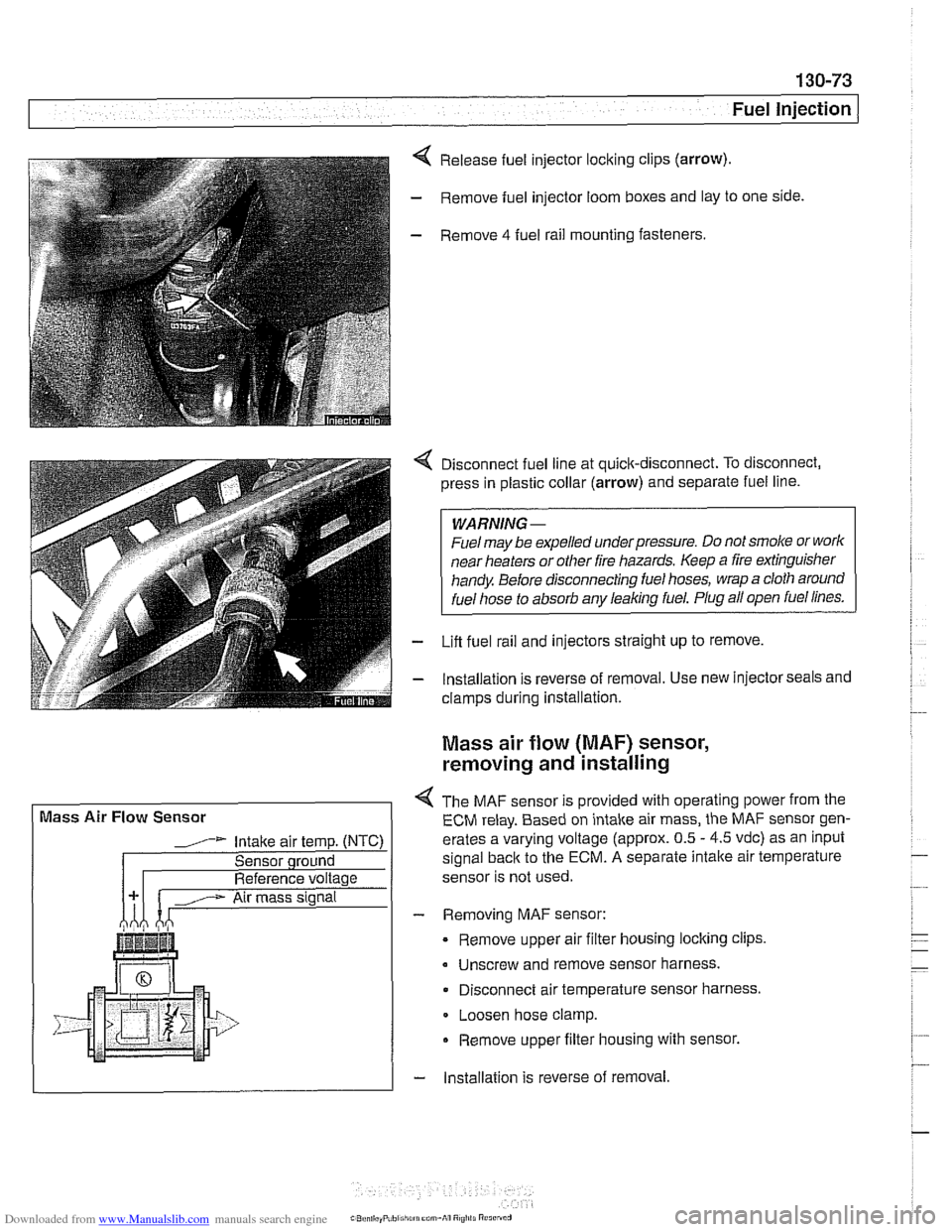
Release fuel injector locking clips (arrow).
- Remove fuel injector loom boxes and lay to one side.
- Remove 4 fuel rail mounting fasteners.
4 Disconnect fuel line at quick-disconnect. To disconnect,
press in plastic collar (arrow) and separate fuel line.
WARNING -
Fuel may be expelled underpressure. Do not srnol(e or work
near heaters or
other fire hazards. Keep a fire extinguisher
handy. Before disconnecting fuel hoses, wrap a cloth around
fuel hose
to absorb anv leakinq fuel. Plug all open fuel lines.
- Lifl fuel rail and injectors straight up to remove.
- lnstallation is reverse of removal. Use new injector seals and
clamps during installation.
Mass air flow (MAF) sensor,
removing and installing
4 The MAF sensor is provided with operating power from the
ECM relay. Based on intake air mass, the MAF sensor gen-
erates a varying voltage (approx. 0.5
- 4.5 vdc) as an input
signal
back to the ECM. A separate intalte air temperature
sensor is not used.
- Removing MAF sensor:
Remove upper air filter housing locking clips
Unscrew and remove sensor harness.
Disconnect air temperature sensor harness.
Loosen hose clamp.
Remove upper filter housing with sensor.
- lnstallation is reverse of removal
Page 465 of 1002
Downloaded from www.Manualslib.com manuals search engine
130-75
Fuel Injection
Secondary air injection, overview
The secondary air system pumps ambient air into the exhaust
stream afteracoid engine start to reduce the warm-up time of
the catalytic converters and to reduces HC and CO emis-
sions. The ME
7.2 ECM controls and monitors the secondary
air injection system. The secondary air pump operates at a
starttemperature of between 10°C
(50°F) and 40°C (104°F).
and continues to operate for a maximum of
2 minutes at idle
speed.
The electric air pump draws in ambient air and supplies it to
the
checlc valve. The vacuum vent valve (solenoid) switches
vacuum to open the
checlc valve when activated by the ECM.
Once opened, the checlc
valve allows air to be pumped into
the exhaust stream.
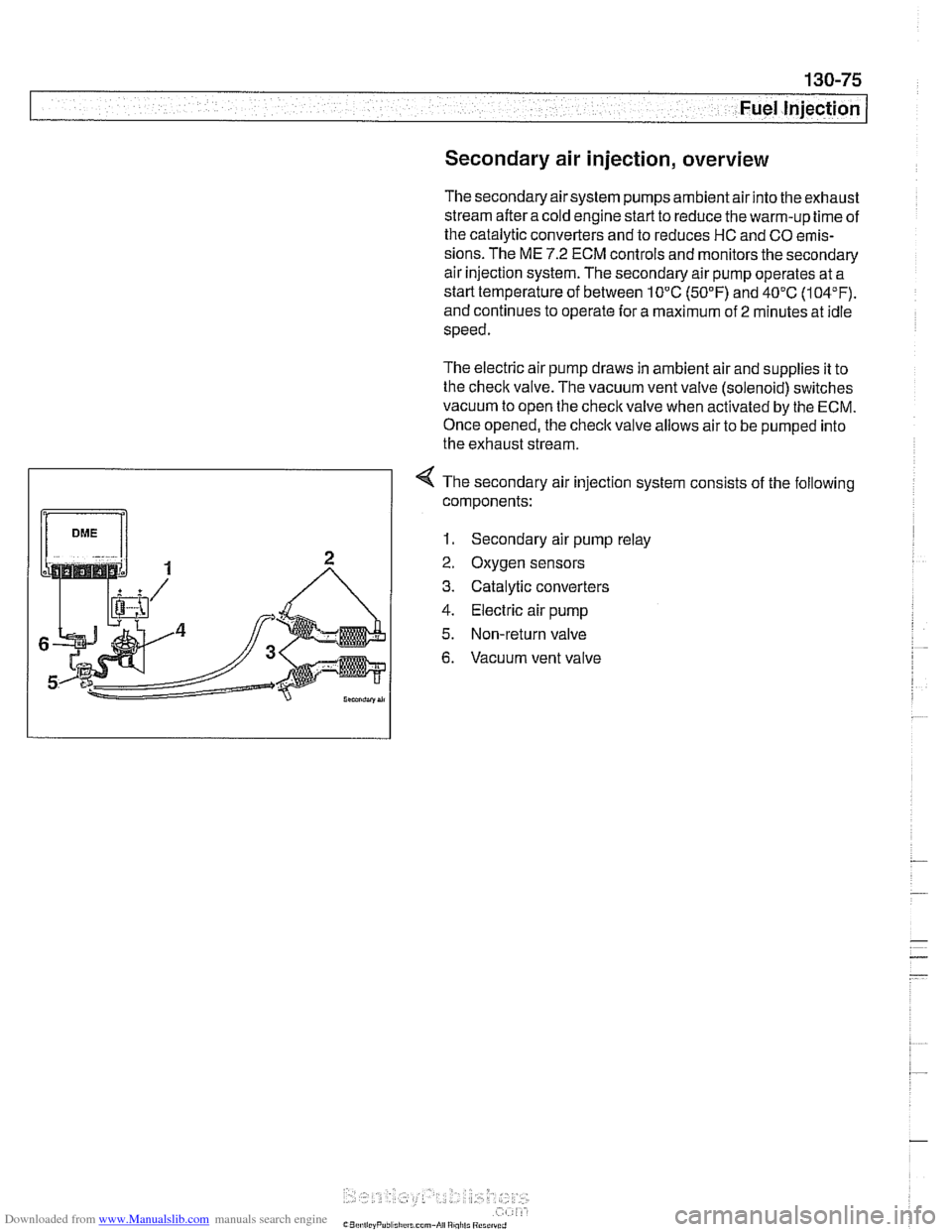
4 The secondary air injection system consists of the following
components:
1. Secondary air pump relay
2. Oxygen sensors
3. Catalytic converters
4. Electric air pump
5. Non-return valve
6. Vacuum vent valve
Page 467 of 1002
Downloaded from www.Manualslib.com manuals search engine
Fuel lnjection
I 1- I
4 /output l~em~erature signal. E-box fan I E-box fan
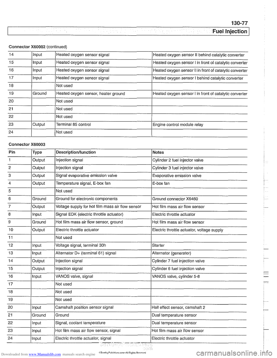
Connector
X60002 (continued)
14
15
16
17
18
19
20
21
22
23
24
5
6
7
8
9
10
11
12
13
14
15
16
Input
Input
Input
Input
Ground
Output Heated
oxygen sensor signal
Heated oxygen sensor signal
Heated oxygen sensor signal
Heated oxygen sensor signal
Not used
Heated oxygen sensor, heater ground
Not used
Not used
Not used
Terminal 85 control
Not used Heated oxygen sensor
II behind catalytic converter
Heated oxygen sensor
I in front of catalytic converter
Heated oxygen sensor
I1 in front of catalytic converter
Heated oxygen sensor
I behind catalytic converter
Heated oxygen sensor I in front of catalytic converter
Engine control module relay
Connector
X60003
Ground
Output Input
Ground
Output
Input
Input
Output
Output
Input
Pin 1
2
3
Not used
Ground for electronic components
Voltage supply for hot
film mass air flow sensor
Signal EDK (electric throttle actuator) Hot film mass air flow sensor, ground
Electric throttle actuator
Not used
Voltage signal, terminal 30h
Alternator
D+ (terminal 61) signal
Injection signal
Injection signal
VANOS valve, signal
Type
Output
Output
Output
Ground connector
X6460
Hot film mass air flow sensor
Electric throttle actuator
Hot film mass air flow sensor
Electric throttle actuator, voltage supply
Starter
Alternator (generator)
Cylinder
7 fuel injection valve
Cylinder 6 fuel injection valve
VANOS valve, cylinder
5-8
Descriptionlfunction
Injection signal
Injection signal
Signal evaporative emission valve Notes
Cylinder 2 fuel injector valve
Cylinder 3 fuel injector valve
Evaporative emission valve
Page 468 of 1002
Downloaded from www.Manualslib.com manuals search engine
I Fuel Injection
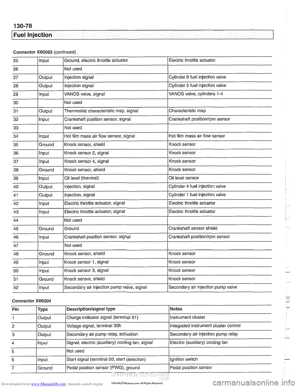
Connector X60003 (continued) Electric throttle actuator
25
- 27 28
29
30
31
32
33
I I I
36 jlnput I Knoclc sensor 2, signal 1 Knock sensor
I I I
Input
26
Output
Output
input
Output
Input
I ' I . I
43 1 ln~ut I Electric throttle actuator, signal (Electric throttle actuator
Ground, electric throttle actuator
1 Not
used
Hot film mass air flow sensor
34
- 37
38
39
40
41
42
injection signal
Injection
signal
VANOS valve, signal
Not used
Thermostat characteristic map, signal
Crankshaft position sensor, signal
Not used
35 l~round I~nock sensor, shield 1 ~nock sensor
Cylinder
8 fuel injection valve
Cylinder
5 fuel injection valve
VANOS valve, cylinders
1-4
Characteristic map
Crankshaft positionlrpm sensor
input
input
Ground
Input
Output
Output
Innut
Hot film mass air flow sensor, signal
I
44
45 46
47
48
49
50
51
52
Connector )(GO004
Knock sensor 4, signal
Knock sensor, shield
Oil
level (thermal)
Injection, signal
Injection, signal
Electric throttle actuator, signal
Not used
Ground
Crankshaft position sensor, signal
Not used
Knoclc sensor, shield
Knock sensor
1, signal
Knock sensor
3, signal
Knock sensor, shield
Secondary air injection pump valve, signal
'
Ground
Input
Ground
input Input
Ground
Input
I' I ... I . ~
Knock sensor
Knocic sensor
Oil level sensor
Cylinder
4 fuel injection valve
Cylinder
1 fuel injection valve
Electric throttle actuator
Crankshaft sensor shield
Crankshaft
positionlrprn sensor
Knock sensor
Knock sensor
Knock sensor
Knock sensor
Secondary air injection pump valve
Notes
Instrument cluster
Integrated instrument cluster control
Secondary air injection pump
relay
Pin
1
2
3
Electric (auxiliary) cooling fan 4
Type
Output
Output
Outout
Descriptionlsignal type
Charge indicator signal (terminal
61)
Voltage signal, terminal 30h
Secondam air pump relay, activation
Input
5
Signal, electric (auxiliary) cooling fan, signal
I~ot used
Page 469 of 1002
Downloaded from www.Manualslib.com manuals search engine
Fuel Injection I
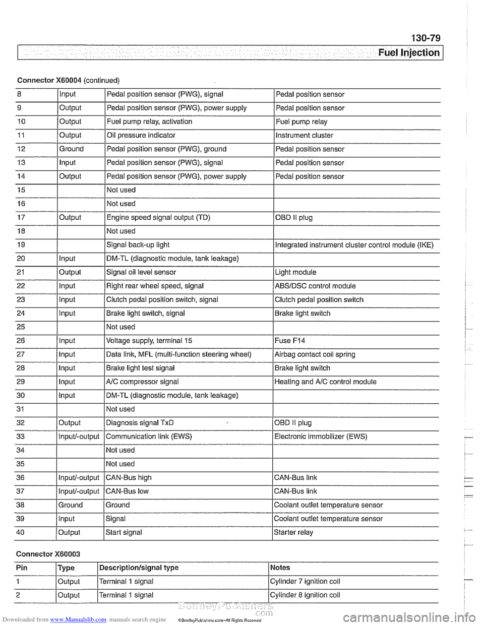
Connector X60004 (continued)
8 10
11
12
13
14
15
16
9
Output 0
Input
17
18
19
20
21
22
23
24
25
26
27
28
29
30
31
32
33
34
35
36
39
llnput lsignal l~oolant outlet temperature sensor
Output
Output
Ground
Input
Output
I I - I
40 /output Istart signal Istarter relay
Pedal position sensor (PWG), signal
Output Input
Output
input
Input
Input
Input
Input
Input
input
Input
Output
Input/-output
Input/-output
37
Connector X60003
Pedal position sensor
Fuel pump relay, activation
Oil pressure indicator Pedal position sensor (PWG), ground
Pedal position sensor (PWG), signal
Pedal position sensor (PWG), power supply
Not used
Not used Fuel
pump relay
Instrument cluster
Pedal position sensor
Pedal position sensor
Pedal position sensor
Engine speed signal output (TD)
Not used
Signal
back-up light
DM-TL (diagnostic module,
tank leakage)
Signal oil level sensor
Right rear wheel speed, signal
Clutch pedal position switch, signal
Brake light switch, signal
Not used
Voltage supply, terminal
15
Data link, MFL (multi-function steering wheel)
Brake light test signal
AJC compressor signal
DM-TL (diagnostic module, tank
leakage)
Not used
Diagnosis signal
TxD
Communication link (EWS)
Not used
Not used
CAN-BUS hiqh
38 1 Ground l~round I Coolant outlet temperature sensor
OED II plug
Integrated instrument cluster control module (IKE)
Light module
ABSIDSC control module
Clutch pedal position switch
Brake light switch
Fuse
F14
Airbag contact coil spring
Brake light switch
Heating and
A/C control module
OBD
II plug
Electronic immobilizer (EWS)
CAN-Bus link
CAN-Bus link
Input/-output CAN-Bus low
Page 471 of 1002
Downloaded from www.Manualslib.com manuals search engine
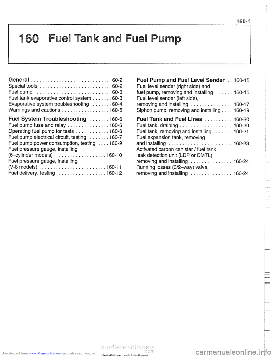
160 Fuel Tank and Fuel Pump
General ........................... .I6 0.2
Special tools ........................ .I6 0.2
Fuel pump ......................... .I6 0.3
Fuel tank evaporative control system ..... .I6 0.3
Evaporative system troubleshooting ..... .I6 0.4
Warnings and cautions ................ .I6 0.5
Fuel System Troubleshooting ...... .I6 0.6
Fuel pump fuse and relay .............. .I6 0.6
Operating fuel pump for tests ........... .I6 0.6
Fuel pump electrical circuit, testing ...... .I6 0.7
Fuel pump power consumption, testing ... .I6 0.9
Fuel pressure gauge, installing
(6-cylinder models)
................. .I6 0.1 0
Fuel pressure gauge, installing
(V-8 models) ....................... .I6 0.1 1
Fuel delivery, testing ................ .I6 0.12
Fuel Pump and Fuel Level Sender . . 160-15
Fuel level sender (right side) and
fuel pump. removing and installing
...... 160-15
Fuel level sender (left side).
removing and installing
............... 160-17
Siphon pump. removing and installing .... 160-1 9
Fuel Tank and Fuel Lines .......... 160-20
Fuel tank. draining ................... 160-20
Fuel tank. removing and installing ....... 160-21
Fuel expansion tank. removing
and installing
....................... 160-23
Activated carbon canister I fuel tank
leak detection unit
(LDP or DMTL).
removing and installing ............... 160-24
Running losses (312-way) valve.
removing and installing
............... 160-24
Page 476 of 1002
Downloaded from www.Manualslib.com manuals search engine
.-- -
/ Fuel Tank and Fuel Pump - .. -. -- 1
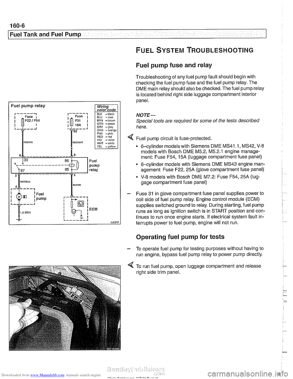
Fuel pump fuse and relay
Troubleshooting of any fuel pump fault should begin with
checking the fuel pump fuse and the fuel pump relay. The
DME main relay should also be checked. The fuel pump relay
is located behind right side luggage compartment interior
panel.
I Fuel pump relay
BLU =blue ERN = blo$,m GRN =groan GRY = grsy ORG =orange PNI< =pink RED =red VIO =violel WHT = wlilte
rk-; I I 1 ECM
I I I 31 8 ,._--___.I
NOTE-
Special tools are required for some of the tests described
here.
4 Fuel pump circu~t is fuse-protected.
0 6-cylinder models with Siemens DME MS41 .I, MS42, V-8
models with Bosch DME M5.2, M5.2.1 englne manage-
ment: Fuse
F54,15A (luggage compartment fuse panel)
6-cylinder models with Siemens DME MS43 engine man-
agement: Fuse
F22,25A (glove compartment fuse panel)
V-8 models with Bosch DME M7.2: Fuse F54,25A (lug-
gage compartment fuse panel)
- Fuse 31 in glove compartment fuse panel supplies power to
coil side of fuel pump relay. Engine control module (ECM)
supplies switched ground to relay. During starting, fuel pump
runs as long as ignition switch is in START position and con-
tinues to run once engine starts. If electrical system fault in-
terrupts power to fuel pump, engine will not run.
. .
Operating fuel pump for tests
- To operate fuel pump for testing purposes without having to
run engine, bypass fuel pump relay to power pump directly.
< To run fuel pump, open luggage compartment and release
right side trim panel.
Page 477 of 1002
![BMW 540i 1998 E39 Service Manual Downloaded from www.Manualslib.com manuals search engine
- Fuel Tank and Fuel pump]
Remove fuel pump
relay (arrow).
4 Connect relay socitet terminal 6 (redlviolet wire) to relay
socket termi BMW 540i 1998 E39 Service Manual Downloaded from www.Manualslib.com manuals search engine
- Fuel Tank and Fuel pump]
Remove fuel pump
relay (arrow).
4 Connect relay socitet terminal 6 (redlviolet wire) to relay
socket termi](/img/1/2822/w960_2822-476.png)
Downloaded from www.Manualslib.com manuals search engine
- Fuel Tank and Fuel pump]
Remove fuel pump
relay (arrow).
4 Connect relay socitet terminal 6 (redlviolet wire) to relay
socket terminal
2 (whitelblue wire) with a fused jumper wire.
After completing tests, remove jumper harness.
CA
UTIOG
Relay locations may vary Use care when identifying relays
and making electrical checks at
the fuse/relay panel. See
610 Electrical Component Locations for additional re-
lay information.
The fuel pump relay has a 1.5
md red/violet wire at
terminal
6 in the relay socket. Terminal2 has a 2.5md
white/blue wire. See ELE Electrical Wiring Diagrams
for additional wiring information.
NOTE-
* The fuel pump will run as soon as the jumper wire Is at-
tached.
The jumper wire should be 1.5
md (14 ga.) and include
an in-line fuse holder with a 15A fuse. To avoid
fuse/relay
panel damage from repeated connecting and disconnect-
ing, also include a toggle switch in the jumper harness.
- If pump does not run with jumper installed, fault could be in
fuel pump, fuses
F31 or F22 1 F54, or wiring to pump. Check
pump, fuses and its wiring as described below.
Fuel pump electrical circuit, testing
- The test given below assumes that the fuel pump relay circuit
is functioning correctly as described earlier. Access to the
pump is from below the rear seat bottom cushion.
- Remove rear seat lower cushion by lifting front edge off left
and right catches.
Page 478 of 1002
Downloaded from www.Manualslib.com manuals search engine
160-8
I Fuel Tank and Fuel Pump
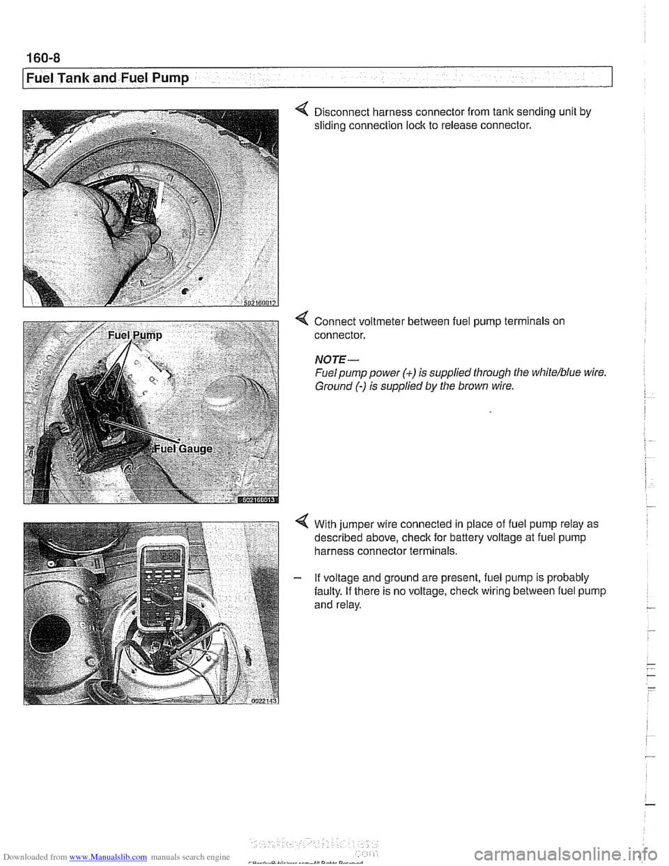
4 Disconnect harness connector from tank sending unit by
sliding connection lock to release connector.
Connect voltmeter between fuel pump terminals on
connector.
NOTE-
Fuel pump power (+) is supplied through the white/blue wire
Ground
(-) is supplied by the brown wire.
With jumper wire connected in place of fuel pump relay as
described above, check for battery voltage at fuel pump
harness connector terminals.
If voltage and ground are present, fuel pump is probably
faulty. If there is no voltage, check wiring between fuel pump
and relay.