display BMW 540i 1998 E39 Workshop Manual
[x] Cancel search | Manufacturer: BMW, Model Year: 1998, Model line: 540i, Model: BMW 540i 1998 E39Pages: 1002
Page 36 of 1002
Downloaded from www.Manualslib.com manuals search engine
020-4
Maintenance
1997 to 2000 models
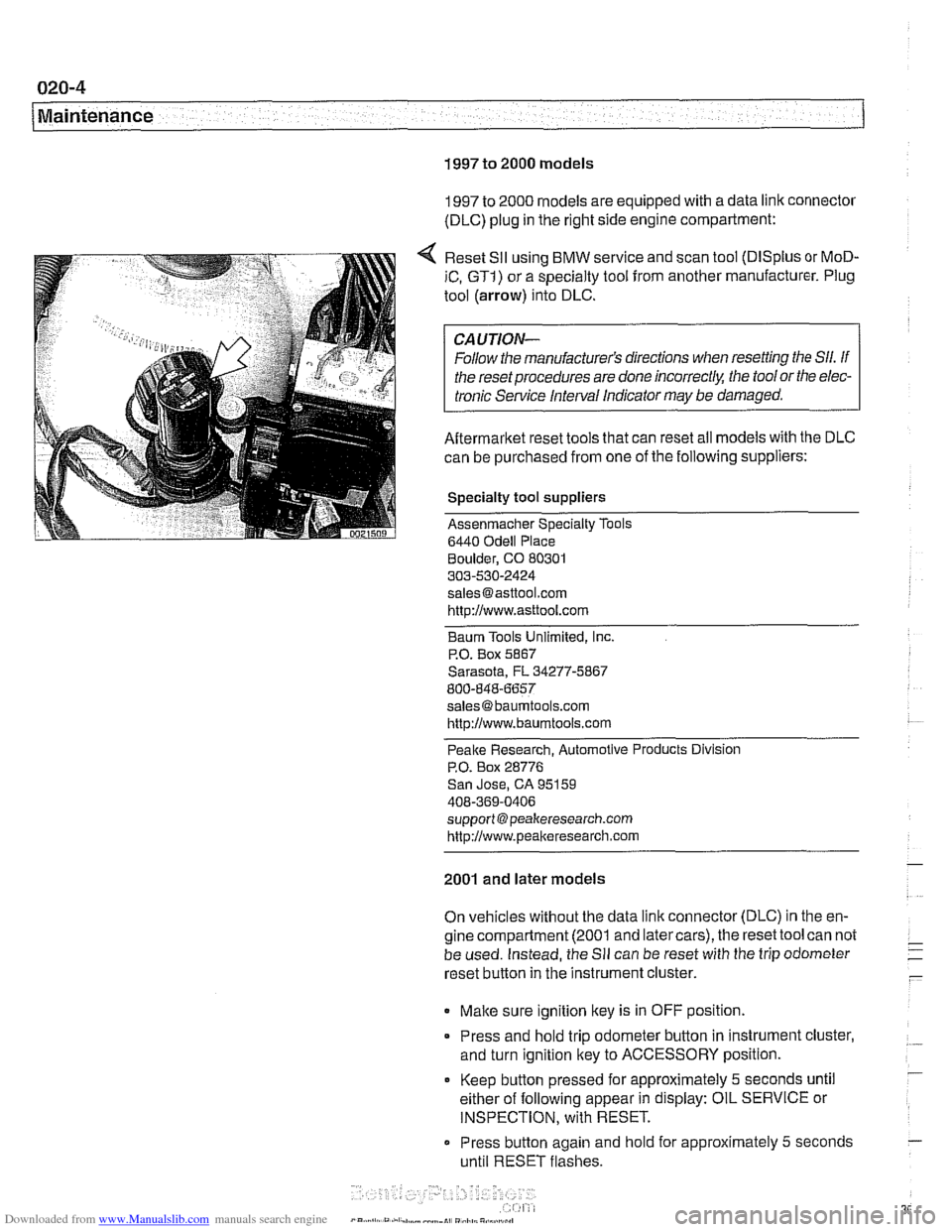
1997 to 2000 models are equipped with a data link connector
(DLC) plug in the right side engine compartment:
Reset
SII using BMW service and scan tool (DISplus or MoD-
iC, GTI) or a specialty tool from another manufacturer. Plug
tool (arrow) into DLC.
CAUTION-
Follow the manufacturer's directions when resetting the Sll. If
the reset procedures are done
incorrect& the tool or the elec-
tronic Service Interval Indicator
may be damaged.
Aftermarket reset tools that can reset all models with the DLC
can be purchased from one of the following suppliers:
Specialty tool suppliers
Assenmacher Specialty Tools
6440
Odell Place
Boulder, CO 80301
303-530-2424
[email protected] http://www.asttool.com
Baum Tools Unlimited,
Inc.
P.O. Box 5867
Sarasota, FL 34277-5867
800-848-6657
[email protected]
http://www.baumtools.com
Peake Research. Automotive Products Division
P.O. Box 28776
San Jose, CA 95159
408-369-0406
support @peakeresearch.com
http://www.peal~eresearch.com
2001 and later models
On vehicles without the data link connector (DLC) in the en-
gine compartment (2001 and latercars), the reset tool can not
be used. Instead, the
Sll can be reset with the trip odometer
reset button in the instrument cluster.
Make sure ignition key is in OFF position.
* Press and hold trip odometer button in instrument cluster,
and turn ignition key to ACCESSORY position.
Keep
button pressed for approximately 5 seconds until
either of following appear in display: OIL SERVICE or
INSPECTION, with RESET.
Press button again and
hold for approximately 5 seconds
until RESET flashes.
Page 37 of 1002
Downloaded from www.Manualslib.com manuals search engine
Maintenance
0 Service due is shown with RESET if the measured con-
sumption limit has been reached and resetting is possible.
If RESET is not shown, the minimum limit has not been
reached and resetting is not possible.
While display is flashing, press button briefly to reset
Sll.
After display has shown new interval, the following will
appear in display for approximately
2 seconds: END SIA.
NOTE-
The system can only be reset again after the vehicle has
been driven approximately 50 to
75 miles (consumes at
least2.5gallons of fuel). If the display shows RESETwhen
resetting, the minimum driving distance has been fulfilled
and the system can be reset again.
0 It is possible to interrupt and end the reset procedure by
changing the position of the ignition
ley.
lnspection I, lnspection II
The Service Interval Indicator (SII) signals the need for main-
tenance and inspection. There are two sets
of inspection re-
quirements, alternating throughout a car's maintenance
history. If the last inspection interval was lnspection I, the next
inspection interval (following an oil service) will be lnspection
11, the next after that will be lnspection I, and so on.
lnspection
I tasks are listed in Table b. lnspection I Service.
lnspection
II includes most of the tasks from lnspection I with
additional lnspection
II tasks. A complete listing of lnspection
II tasks is in Table c. lnspection I1 Service.
NOTE-
For reference, the BMW lnspection I and lnspection I1 re-
quirements are approximately equivalent to the maintenance
requirements that other European manufacturers specify.
ln-
spection I is normally due at intervals with a maximum of
30,000 miles or
24 months. lnspection I1 is normally due at
intervals with a maximum of 60,000 miles or
48 months.
Page 70 of 1002
Downloaded from www.Manualslib.com manuals search engine
100-4
I Engine-General
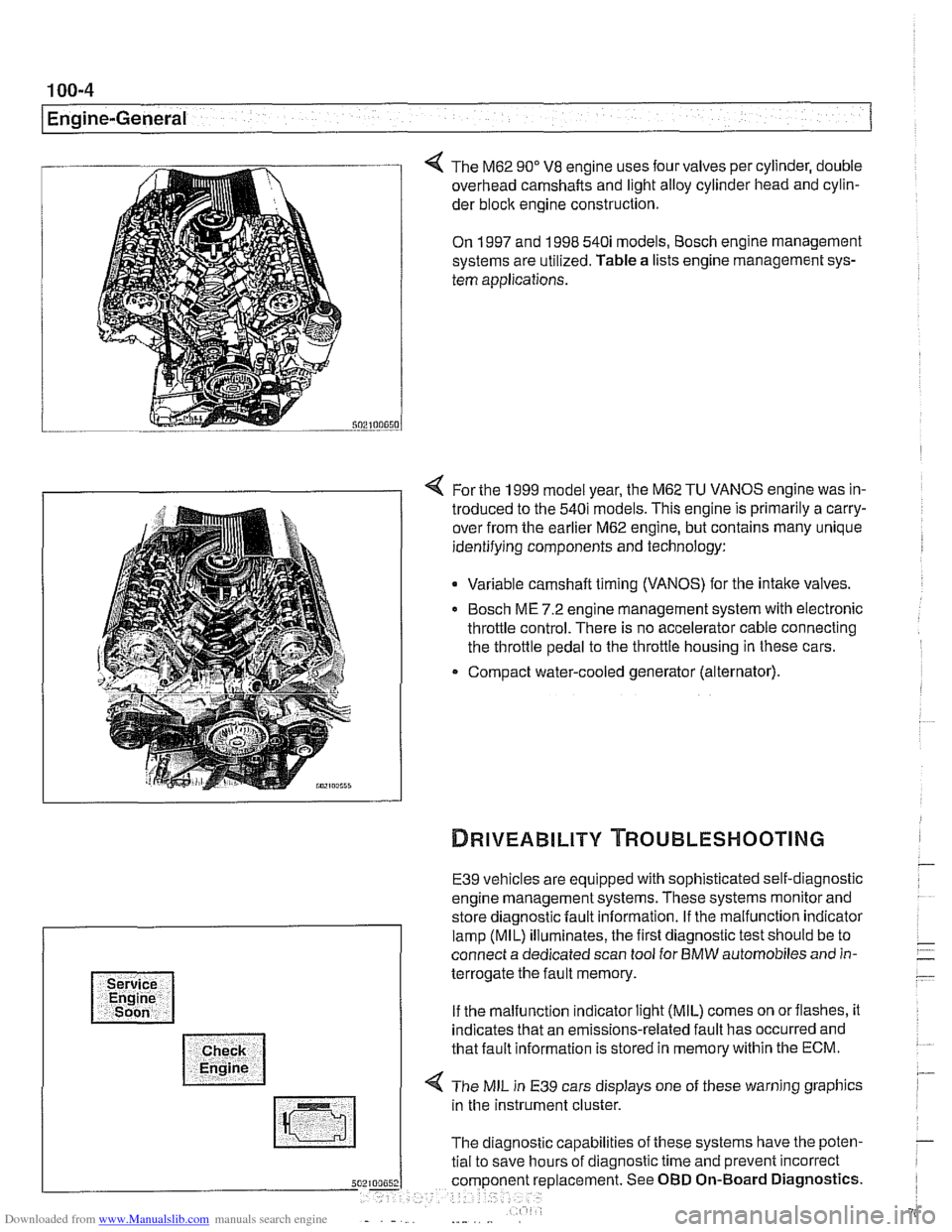
The M62 90" V8 engine uses four valves per cylinder, double
overhead camshafts and light alloy cylinder head and cylin-
der
bloclc engine construction.
On 1997 and 1998 540i models, Bosch engine management
systems are utilized. Table a lists engine management sys-
tem applications.
4 For the 1999 model year, the M62 TU VANOS engine was in-
troduced to the 540i models. This engine is primarily a carry-
over from the earlier M62 engine, but contains many unique
identifying components and technology:
Variable camshaft timing (VANOS) for the intake valves.
Bosch ME 7.2 engine management system with electronic
throttle control. There is no accelerator cable connecting
the throttle pedal to the throttle housing in these cars.
Compact water-cooled generator (alternator).
E39 vehicles are equipped with sophisticated self-diagnostic
engine management systems. These systems monitor and
store diagnostic fault information. If the malfunction indicator
lamp (MIL) illuminates, the first diagnostic test should be to
connect a dedicated scan tool for BMW automobiles and in-
terrogate the fault memory.
If the malfunction indicator light (MIL) comes on orflashes, it
indicates that an emissions-related fault has occurred and
that fault information is stored in memory within the ECM.
4 The MIL in E39 cars displays one of these warning graphics
in the instrument cluster.
The diagnostic capabilities of these systems have the poten-
tial to save hours of diagnostic time and prevent incorrect
5 placement. See OBD On-Board Diagnostics.
Page 805 of 1002
Downloaded from www.Manualslib.com manuals search engine
Instrument cluster
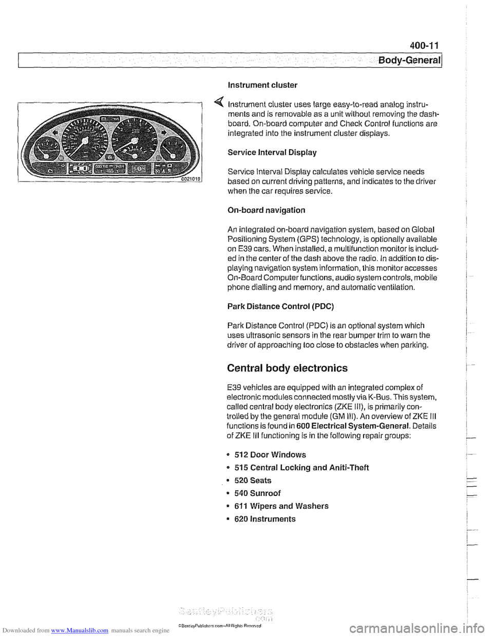
Instrument cluster uses large easy-to-read analog instru-
ments and is removable as a unit without removing the dash-
board. On-board computer and Check Control functions are
integrated into the instrument cluster displays.
Service Interval Display
Service Interval Display calculates vehicle service needs
based on current driving patterns, and indicates to the driver
when the car requires
service
On-board navigation
An integrated on-board navigation system, based on Global
Positioning System (GPS) technology, is optionally available
on
E39 cars. When installed, a multifunction monitor is includ-
ed in the center of the dash above the radio. in addition to dis-
playing navigation system information, this monitor accesses
On-Board Computerfunctions, audiosystem controls, mobile
phone dialling and memory, and automatic ventilation.
Park Distance Control (PDC)
Park Distance Control (PDC) is an optional system which
uses ultrasonic sensors in the rear bumper trim to warn the
driver of approaching too close to obstacles when parlting.
Central body electronics
E39 vehicles are equipped with an integrated complex of
electronic modules connected mostly via K-Bus. This system,
called central body electronics (ZKE
Ill), is primarily con-
trolled by the general module (GM
Ill). An overview of ZKE Ill
functions is found in 600 Electrical System-General. Details
of ZKE
Ill functioning is in the following repair groups:
- 512 Door Windows
* 515 Central Locking and Aniti-Theft
520 Seats
a 540 Sunroof
611 Wipers and Washers
620 Instruments
Page 906 of 1002
Downloaded from www.Manualslib.com manuals search engine
51 5-12
I Central Locking and Anti-Theft
Key battery
9
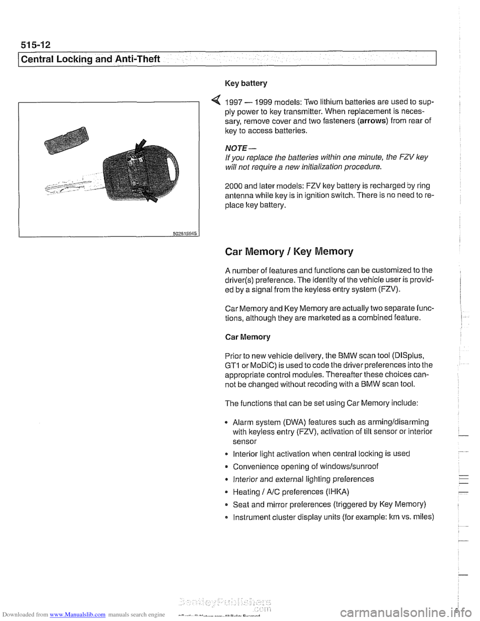
4 1997 - 1999 models: Two lithium batteries are used to sup-
ply power to key transmitter. When replacement is neces-
sary, remove cover and two fasteners (arrows) from rear of
key to access batteries
NOTE-
If you replace the batteries within one minute, the FZV ley
will not require a new initialization procedure.
2000 and later models: FZV key battery is recharged by ring
antenna while ltey is in ignition switch. There is no need to re-
place ltey battery.
Car Memory 1 Key Memory
A number of features and functions can be customized to the
driver(s) preference. The identity of the vehicle user is provid-
ed by a
s~gnal from the keyless entry system (FZV).
Car Memory and Key Memory are actually two separate func-
tions, although they are marketed as a combined feature.
Car Memory
Pr'or ro new
veh c,e de very, the BMW scan roo (DISp us,
GTI or MOD C) is ~sed lo cooc ine driver preierences nro ine
appropriate control modules. Thereafter these choices can-
not be changed without
recoding with a BMW scan tool.
The functions that can be set using Car Memory include:
Alarm system (DWA) features such as armingldisarming
with
lkeyless entry (FZV), activation of tilt sensor or interior
sensor
lnterior light activation when central
locking is used
Convenience opening of
windows/sunroof
lnterior and external lighting preferences
Heating
I A/C preferences (IHKA)
Seat and mirror preferences (triggered by Key Memory)
Instrument cluster display units (for example: km vs. miles)
Page 952 of 1002
Downloaded from www.Manualslib.com manuals search engine
I Airbag System (SRS)
Two-stage airbag (MRS Ill)
Beginning with 2000 model year (911 999 production) the front
airbags were changed to a two-stage style airbag. This en-
sures that the force of
airbag inflation is not greater than nec-
essary to provide
protection. The airbags are designed to
Drovide "soit" de~lovment if the acceleration sensor detects a
iow-speed impact, and "hard deployment in higher speed im-
pacts.
NOTE-
A two-stage passenger airbag was used on cars built be-
tween
9/1998 and 3/1999. This pre-smart technology airbag
used two ignition stages. Stage one is designed to ignite first
during an impact. Stage two ignites after a timed period, as
programmed in the MRS
I1 control module.
Airbag indicator light
The MRS control module detects and stores system status
The
airbag indicator light in the instrument cluster displays
the status of the
airbag system when the ignition key is in "ac-
cessory" or
ON positions.
System normal: lndicator light comes on briefly, then goes
out.
- System malfunction: lndicator light fails to come on.
System malfunction: lndicator light comes on briefly, goes
out and lights up again.
The
airbag indicator light also comes on if the seat belt pyro-
technic tensioners have been triggered.
Page 961 of 1002
Downloaded from www.Manualslib.com manuals search engine
OBD On-Board Diagnostics
I I
General ........................... OBD-1 Diaqnostic Trouble Codes (DTCs) . . OBD-9
On-Board Diagnostics (OBD I!) ..... OBD-I
Malfunction Indicator Light (MIL)
........ OBD-2
Scan tools and scan tool display.
........ OBD-3
Diagnostic monitors
.................. OED-4
Drive cycle
......................... OED-6
Readiness codes
.................... OBD-6
Diagnostic trouble codes
(DTCs) ........ OBD-7
-
Automatic transmission diagnostic
trouble codes
....................... OBD-9
Engine diagnostic trouble
codes: M52 engine.
................. OED-13
Engine diagnostic trouble
codes: M54 engine.
................. OBD-17
Engine diagnostic trouble
codes: M62 engine.
................. OBD-24
This chapter outlines the fundamentals and equipment
requirements of On-Board Diagnostics
I1 (OBD 11) standards
as they apply to BMW vehicles. Also covered here is a listing
of BMW and OBD
I1 diagnostic trouble codes (DTCs).
ON-BOARD DIAGNOSTICS (QBD !I)
OBD II standards were developed by the SAE (Society of
Automotive Engineers) and CARB (California Air Resources
Board).
OED I1 is the second generation of on-board self-
diagnostic equipment requirements. These standards were
originally mandated for California vehicles. Since
1996 they
have been applied
toall passengervehicles sold in the United
States.
On-board diagnostic capabilities are incorporated into the
hardware and soflwareof the enginecontrol module
(ECM) to
monitor virtually every component that can affect vehicle
emissions. The
OED I1 system works to ensure that
emissions remain as clean as possible over the life of the
vehicle.
Each emission-influencing component is checked by a
diagnostic routine (called a monitor) to verify that it is
functioning properly.
If a problem or malfunction is detected,
the
diagnostic executive built into the OBD I1 system
illuminates a malfunction indicator light (MIL) on the
instrument panel.
The OBD
I1 system also stores diagnostic trouble codes
(DTCs) about the detected malfunction in the ECM so that a
repair technician can accurately find and fix the problem.
Page 963 of 1002
Downloaded from www.Manualslib.com manuals search engine
OBD-3
On-Board
~iactnosticsl
Additional MIL information:
A fault code is stored within the ECM upon the first
occurrence of a fault in the system being checlted.
Two complete consecutive drive cycles with the iault
present illuminate the MIL. The exception to the two-fault
requirement is a catalyst-damaging fault, which illuminates
the MIL immediately.
If the second drive cycle was not complete and the fault
was not checked, the ECM counts the third drive cycle as
the next consecutive drive cycle. The MIL illuminates
if the
system is checked and the fault is still present.
Once the MIL is illuminated, it remains illuminated until the
vehicle completes three consecutive drive cycles without
detecting a fault.
0 An existing fault code is cleared from memory
automatically when the vehicle completes
40 consecutive
drive cycles without the fault being detected.
In order to automatically clear a catalyst-damaging fault from
memory, the condition underwhich the fault occurred must be
evaluated for 80 consecutive drive cycles without the fault
reoccurring.
A generic scan tool connected to the BMW data link
connector (DLC) or OBD
I1 plug can display diagnostic trouble
codes (DTCs), along with the conditions associated with the
illumination of the MIL. Using a more advanced or
BMW-
dedicated scan tool, additional proprietary information is
normally available.
Scan tool and scan tool display
The complexity of the OBD I1 system requires that all
diagnostics begin by connecting a scan tool to the vehicle.
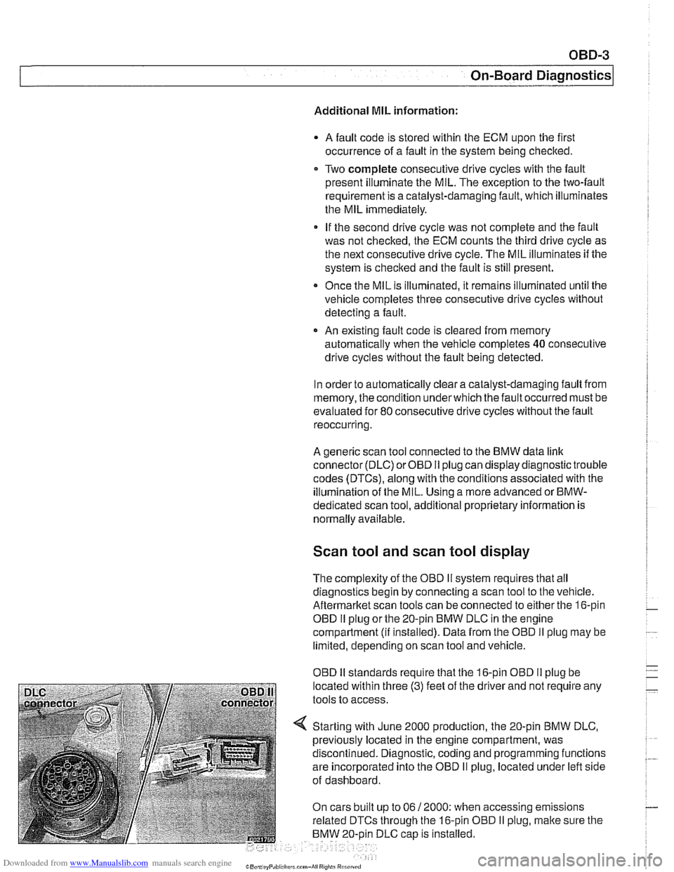
Aftermarltet scan tools can be connected to either the 16-pin
OBD
I1 plug or the 20-pin BMW DLC in the engine
compartment
(ii installed). Data from the OBD II plug may be
limited, depending on scan tool and vehicle.
OBD
I1 standards reouire that the 16-oin OBD I1 oluo be
located within three
(3) feet of the driier and not're&ire any
tools to access.
Starting with June 2000 production, the 20-pin BMW DLC,
previously located in the engine compartment, was
discontinued. Diagnostic, coding and programming functions
are incorporated into the OBD
II plug, located under left side
of dashboard.
On cars built up to 06
/ 2000: when accessing emissions
related DTCs through the 16-pin OBD
I1 plug, malte sure the
BMW 20-oin DLC
caD is installed.
Page 967 of 1002
Downloaded from www.Manualslib.com manuals search engine
On-Board Diagnostics
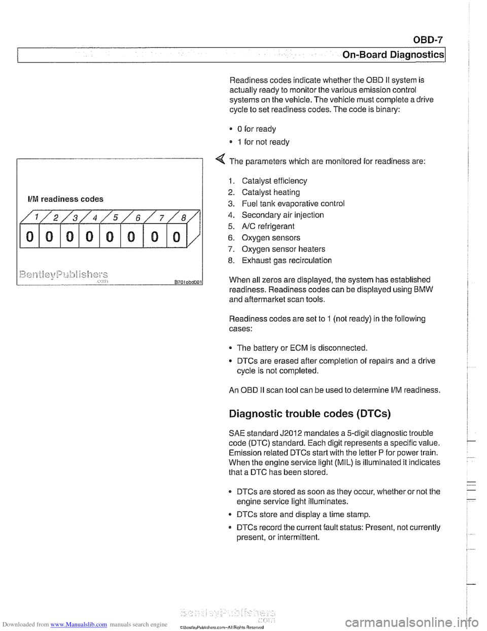
Readiness codes indicate whether the OED Ii system is
actually ready to monitor the various emission control
systems on the vehicle. The vehicle must complete a drive
cycle to set readiness codes. The code is binary:
0 for ready
1 for not ready
f
4 The parameters which are monitored for readiness are:
llM readiness codes
1. Catalyst efficiency
2. Catalyst heating
3. Fuel tank evaporative control
4. Secondary air injection
5.
NC refrigerant
6. Oxygen sensors
7. Oxygen sensor heaters
8. Exhaust gas recirculation
Readiness codes are set to 1 (not ready) in the following
cases:
~9~~.f~[<+t~t~p:,~;:#j~~{]~y~ ,,... , , 8701Dbd001
The battery or ECM is disconnected.
When
all zeros are displayed, the system has established
DTCs are erased after completion of repairs and a drive
cycle is not completed.
readiness. Readiness codes
can be displayed using BMW
and aftermarket scan tools.
An
OED II scan tool can be used to determine IIM readiness.
Diagnostic trouble codes (DTCs)
SAE standard J2012 mandates a 5-digit diagnostic trouble
code (DTC) standard. Each digit represents a specific value.
Emission related DTCs
start with the letter P for power train.
When the engine service
light (MIL) is illuminated it indicates
that a DTC has been stored.
DTCs are stored as soon as they occur, whether or not the
engine service light illuminates.
DTCs store and display a time stamp.
DTCs record the current fault status: Present, not currently
present, or intermittent.