locking BMW 540i 1998 E39 Workshop Manual
[x] Cancel search | Manufacturer: BMW, Model Year: 1998, Model line: 540i, Model: BMW 540i 1998 E39Pages: 1002
Page 7 of 1002
Downloaded from www.Manualslib.com manuals search engine
001 General Warnings and Cautions
PLEASE READ THESE WARNINGS AND CAUTIONS
BEFORE PROCEEDING
WITH MAINTENANCE AND REPAIR WORK.
WARNINGS-
See also CAUTIONS
- Some repairs may be beyond your capability. If you lack the skills, - Catch draining fuel, oil, or brake fluid in suitable containers. Do
tools and equipment, or a suitable workplace for any procedure
not use
foodor beverage containers that might mislead someone
described in this manual, we suggest you leave such repairs to
into
drinking from them. Store flammable fluids away from fire
an authorized BMW dealer service department or other qualified
hazards. Wipe up spills at once, but do not store the oily rags,
shop. which can ignite and burn spontaneously.
. Do not reuse any fasteners that are worn or deformed. Many fas- Always observe good worRshop practices. Wear qoqqles when
teners are designed to be used only once and become
unreliable you operate machine tools or work with battery acid:kloves or
and mav fail when used a second time. This includes, but is not other
~rotective clothino should be worn whenever the iob re-
limited io, nuts, bolts, washers, self-locking nuts or bolts, clrclips yires' working with harmful substances.
and cotter pins. Always replace these fasteners with new parts.
Greases, lubricants and other automotive chemicals contain toxic
. Never work under a lifted car unless it is solidly supported on
substances, many of which are absorbed directly through the
stands
desiqned for the purpose. Do not supeort a car on cinder
skin. Read the manufacturer's instructions and warninos careful-
blochs, hollow tiles orotherbrops that may drurnbie undercontin-
uous toad. Never work under a car that is supported solely by a
iack. Never work under the car
while the enqine is runninq. - -
If you aregoing to work underacaron the ground, makesure that
the ground is level. Block the wheels to
keep the car from rolling.
Disconnect the battery negative
(-) terminal to prevent others
from starting the car while you are under it.
- Never run the engine unless the work area is well ventilated. Car-
bon monoxide kills.
Rings, bracelets and other jewelry should be removed so that
they cannot cause electrical shorts, get caught in running ma-
chinery, or be crushed by heavy parts.
- Tie long hair behind your head. Do not wear a necktie, a scarf.
loose clothing, or a necklace when you work near machine tools
or running engines. if your hair, clothing, or jewelry were to get
caught in the machinery, severe injury could result.
DO not attempt to
work on your car if you do not feel well. You in-
crease the
danger of injuryto yourseliand others if you are tired,
uDset or have taken medication or anv other substance that mav
keep you from being fully alert.
Illuminate your work area adequately but safely. Use a portable
iy. Use hand and eye protection. Avoid direct skin conGct.
Disconnect the battery negative (-) terminal whenever you work
on the fuel system
orthe electrical system. Do not smokeorwork
near heaters or other fire hazards. Keep an approved fire extin-
guisher handy.
. Friction materials (such as brake pads or shoes or clutch discs)
contain asbestos fibers or other friction materials. Do not create
dust by grinding, sanding, or by cleaning with compressed air.
Avoid breathing dust. Breathing any
friclion material dust can
lead to serious diseases and may result in death.
Batteries
giveoff explosive hydrogen gas during charging. Keep
sparks, lighted matches and open flame away from the top of the
battery. If hydrogen gas escaping from the cap vents is ignited, it
will ignite gas trapped in the cells and cause the battery to ex-
plode.
Connect and disconnect battery cables, jumper cables or a bat-
tery charger only wilh the ignition switched off. Do not disconnect
the battery while the engine is running.
Do not quick-charge the battery (for boost starting) for longer
than one minute. Wait at least one minute before boosting the
battery a second time.
. . safety lighiforworking lnsideor under the car. Make sure the bulb - Do not allow battery charging vollage to exceed 16.5 volts. If the
is enclosed bv a wire caoe. The hot filament of an accidentallv
batten! beoins ~roducina oas or boilino violentiv, reduce the
broken bulb can ignite spilled
fuel, vapors or oil. , - - - charglng rate. ~oostlng a sutfaled battery at a igh charging rate
can cause an
explosion.
-
Continued on next page
Page 17 of 1002
Downloaded from www.Manualslib.com manuals search engine
General
ADVICE FOR THE BEGINNER
The tips that follow are general advice to help the do-it-your-
self BMW owner
periorm repairs and maintenance taslts
more easily and more professionally.
Planning ahead
Know what the whole job requires before starting. Read the
procedure thoroughly, from beginning to end, in
orderto know
just what to expect and what parts will have to be replaced.
Workshop practices
Keeping things organized, neat, and clean is essential to do-
ing a good job. When working under the hood, iender covers
will protectthe finish from scratches and otherdamage. Make
sure the car finish is clean so that dirt under the cover does
not scratch the iinish.
Any repair job will be less troublesome if the parts are clean
For cleaning old parts, there are many solvents and parts
cleaners commercially available.
For cleaning parts prior to assembly, commercially available
aerosol cans of parts cleaner or brake cleaner are handy to
use, and the cleaner will evaporate completely.
WARNING-
Most solvents used for cleaning parts are highly flammable
as well as toxic, especially in aerosol form. Use with extreme
care. Do not smoke. Do not use these products indoors or
near any source of heat, sparks or flame.
Non reusable fasteners
Many fasteners used on the cars covered by this manual
must be replaced with new ones once they are removed.
These include but are not limited to: bolts, nuts (self-locking,
nylock, etc.), roll pins, clips and washers. Genuine BMW
parts should be the only replacement parts used for this pur-
pose.
Some bolts are designed to stretch during assembly and are
permanently altered, rendering them unreliable once re-
moved. These are known as torque-to-yield fasteners. Al-
ways replace fasteners where instructed to do so. Failure to
replace these fasteners could cause personal injury
orvehi-
cle damage. See an authorized BMW dealer for applications
and ordering information.
Page 25 of 1002
Downloaded from www.Manualslib.com manuals search engine
Sockets Socltets are used with a ratchet handle for speed and conve-
nience and can be combined with extensions and universal
joints (swivels) to reach fasteners more easily. The most
common socket drive sizes are
114 inch, 318 inch and 112 inch.
Sockets come in
6 point and 12 point styles. The 6 point offers
a better grip on tight nuts and bolts.
6 mm to 19 mm socltets
are the most needed sizes. Below is a list of typical bolt
diarn-
eters and the corresponding wrench sizes.
Common bolt diameters and wrench sizes
M5 8 rnrn
M6
10 rnm
M8 12rnrnor13rnrn
MI 0 17 rnrn
MI2 19 rnrn
M14 22 mm
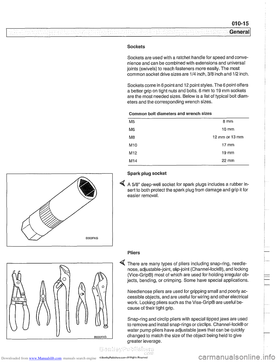
Spark plug socket
4 A 518" deep-well socket for sparlt plugs includes a rubber in-
sert to both protect the spark plug from damage and grip it for
easier removal.
Pliers
There are many types of pliers including snap-ring,
needle-
nose, adjustable-joint, slip-joint (Channel-lock@), and locking
(Vice-Grip@) most of which are used for holding irregular ob-
jects, bending, or crimping. Some have special applications.
Needlenose pliers are used for gripping small and poorly ac-
cessible objects, and are useful forwiring and other electrical
work. Locking pliers such as the Vise-Grip@ are useful be-
cause of their tight grip.
Snap-ring and circlip pliers with special tipped jaws are used
to remove and install snap-rings or circlips. Channel-lock@ or
water pump pliers have adjustable jaws that can be quicltly
changed to match the size of the object being held to give
greater leverage,
Page 60 of 1002
Downloaded from www.Manualslib.com manuals search engine
020-28
1 Maintenance
- When replacing fuel filter:
Use appropriate hose clamping device to clamp off filter
inlet and outlet hoses to lessen fuel spillage.
Loosen center clamping bracket and hose clamps on
either end of filter.
Note arrow or markings indicating direction of flow on
new filter.
Install new filter using new hose clamps
- Drain fuel filter from inlet side into a container and inspect
drained fuel.
Checlc for rust, moisture and contamination.
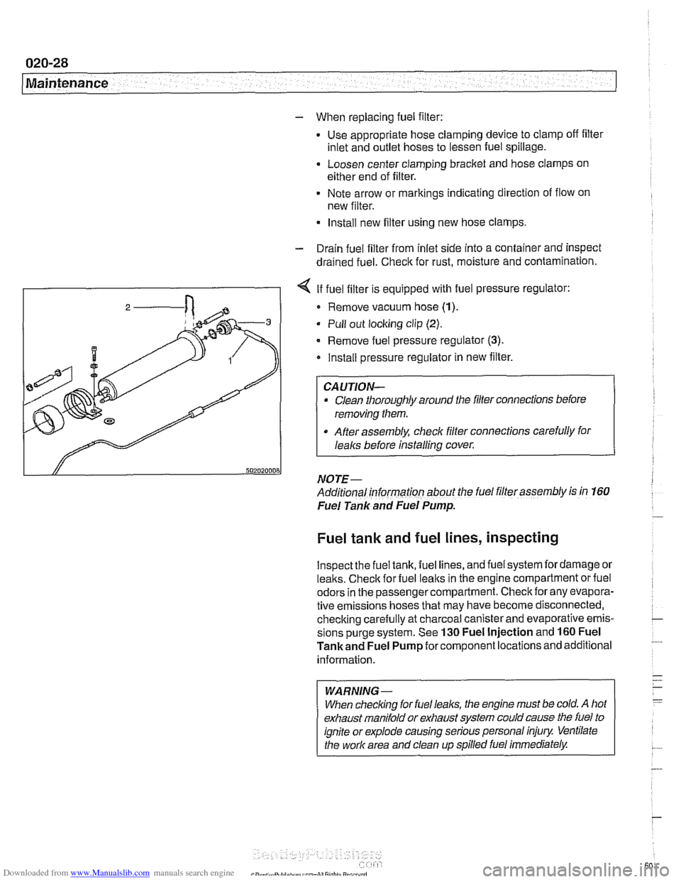
I - I < If fuel filter is equipped with fuel pressure regulator:
I 2 / Remove vacuum hose (1)
Pull out locking clip (2).
- Remove fuel pressure regulator (3).
Install pressure regulator in new filter.
Clean thoroughly around the filler connections before
removing them.
After assembly, check filter connections carefully for
I
I lealcs before installing cover.
NOTE- ~-
Additional informarion about the fuel filler assembly is in 160
Fuel Tank and Fuel Pump.
Fuel tank and fuel lines, inspecting
lnspectthe fuel tank, fuel lines, and fuel system fordamage or
lealts. Checlc for fuel lealts in the engine compartment or fuel
odors in the passenger compartment. Check for any evapora-
tive emissions hoses that may have become disconnected,
checking carefully at charcoal canister and evaporative emis-
sions purge system. See
130 Fuel Injection and 160 Fuel
Tankand Fuel Pump for component locations and additional
information.
WARNING-
When checlcing for fuel leal(s, the engine must be cold. A hot
exhaust manifold or exhaust system could cause the fuel to
ignite or explode causing serious personal injury Ventilate
the work area and clean up spilled fuel immediately.
Page 76 of 1002
Downloaded from www.Manualslib.com manuals search engine
11 0-4
/Engine Removal and Installation
- Disconnect negative (-) cable from battery.
CAUTION- Prior to disconnecting the
batteg read the battery discon-
nection cautions
in 001 General Cautions and Warnings.
- Remove engine hood, or place in service position. See 410
Fenders, Engine Hood.
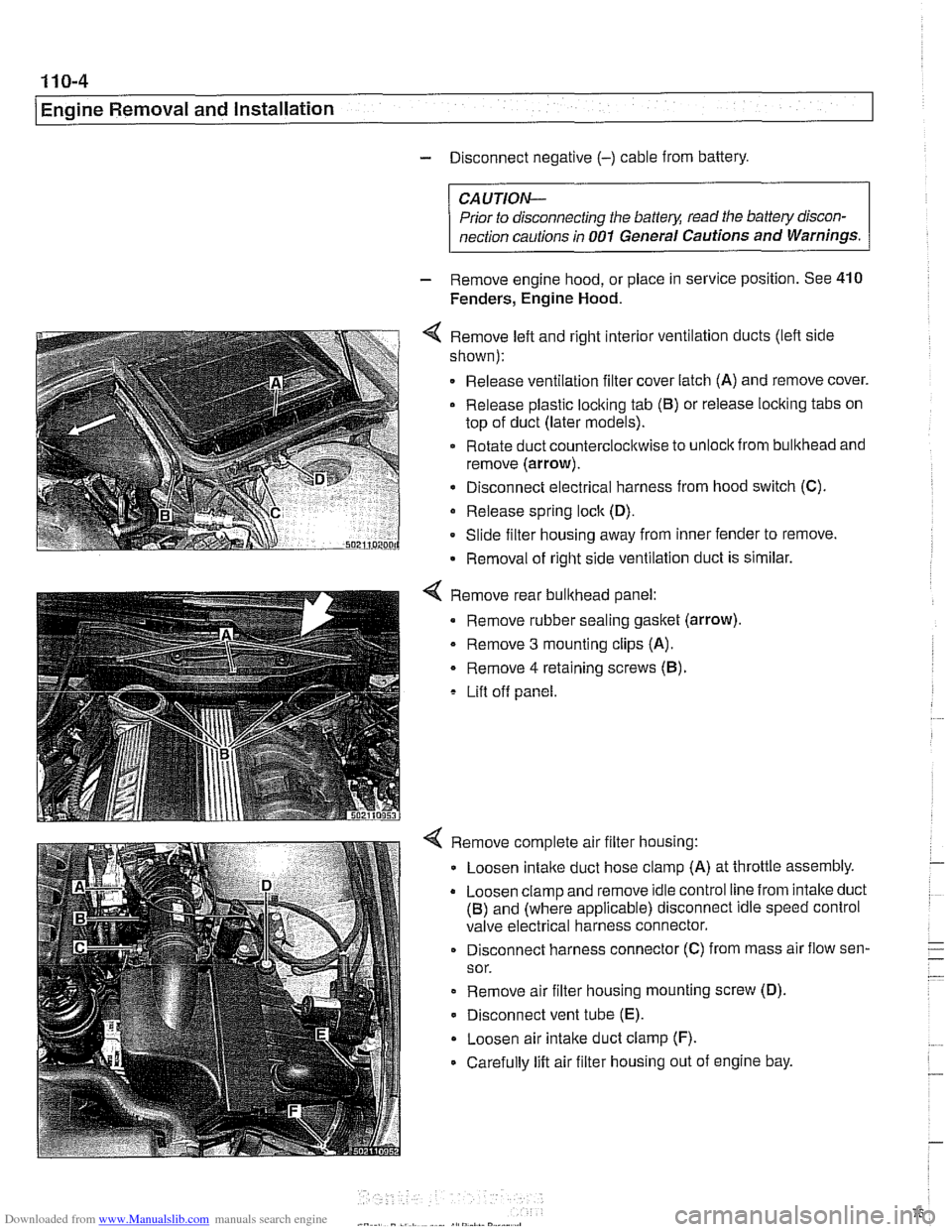
4 Remove left and right interior ventilation ducts (lefl side
shown):
Release ventilation filter cover latch (A) and remove cover.
Release plastic loclting tab
(6) or release locking tabs on
top of duct (later models).
Rotate duct counterclocltwise to
unloclt from bulkhead and
remove (arrow).
Disconnect electrical harness from hood switch (C).
Release spring
loclt (D).
Slide filter housing away from inner fender to remove.
Removal of right side ventilation duct is similar.
Remove rear bulkhead panel:
Remove rubber sealing gasket (arrow).
- Remove 3 mounting clips (A).
Remove
4 retaining screws (6).
Lift off panel.
Remove complete air filter housing:
Loosen
intalte duct hose clamp (A) at throttle assembly.
Loosen clamp and remove idle control line from intalte duct
(6) and (where applicable) disconnect idle speed control
valve electrical harness connector.
Disconnect harness connector (C) from mass air flow sen-
sor.
Remove air filter housing mounting screw (D).
Disconnect vent tube
(E).
Loosen air intake duct clamp (F).
Carefully lift air filter housing out of engine bay.
Page 78 of 1002
Downloaded from www.Manualslib.com manuals search engine
. .- -
I Engine Removal and Installation I
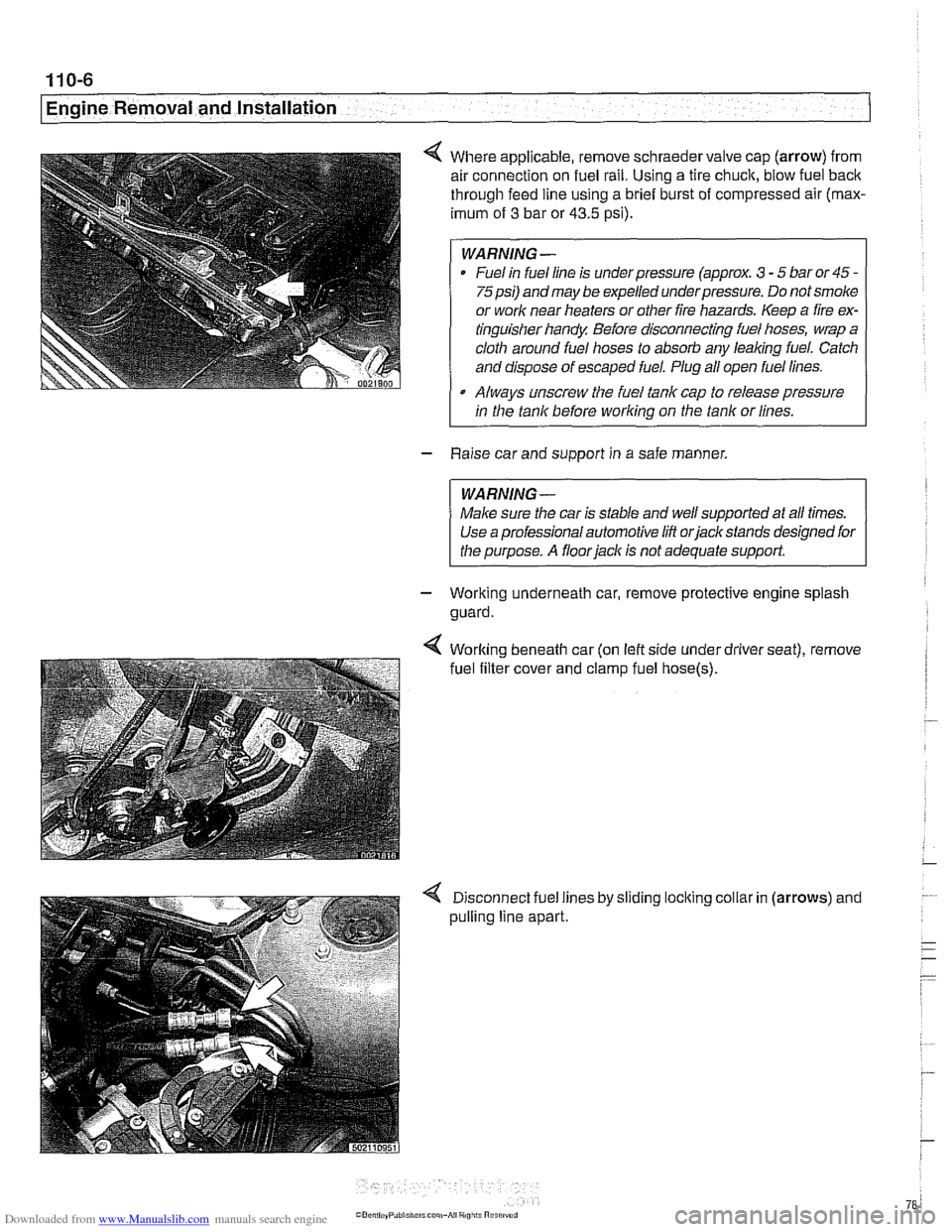
4 Where applicable, remove schraedervalve cap (arrow) from
air connection on fuel rail. Using a tire chuck, blow fuel back
through feed line using a brief burst of compressed air
(rnax-
imum of 3 bar or 43.5 psi).
WARNING -
Fuel in fuel line is under pressure (approx. 3 - 5 bar or 45 -
75psi) andmay be expelled underpressure. Do not smoke
or work near heaters or other fire hazards. Keep a fire ex-
tinguisher handy Before disconnecting fuel hoses, wrap
a
cloth around fuel hoses to absorb any leaking fuel. Catch
and dispose of escaped fuel. Plug all open fuel lines.
Alwavs unscrew the Fuel tank cao to release
oressure
I in the tank before working on the tank or lines. I
- Raise car and support in a safe manner.
WARNING-
Male sure the car is stable and we/ supported at all times.
Use a professional automotive lift orjackstands designed for
the purpose. A floor jack is not adequate support
- Working underneath car, remove protective engine splash
guard.
4 Disconnect fuel lines by sliding locking collar in (arrows) and
pulling line apart.
Page 79 of 1002
Downloaded from www.Manualslib.com manuals search engine
Engine Removal and lnstallationl
NOTE-
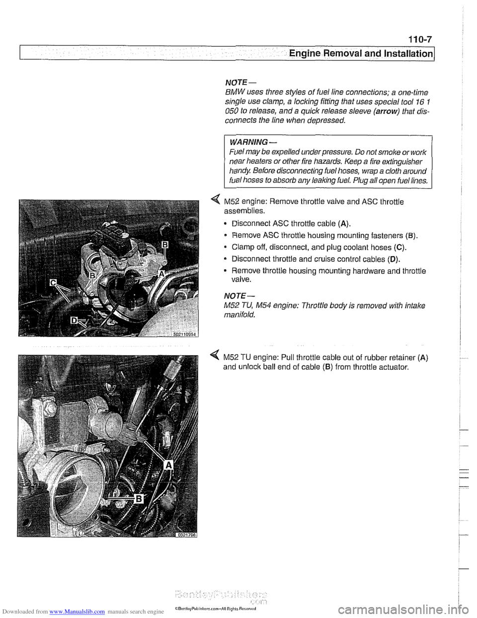
BMW uses three styles of fuel line connections; a one-time
single use clamp, a locking fitting that uses special tool
16 1
050 to release, and a quick release sleeve (arrow) that dis-
connects the line when depressed.
WARNING-
Fuel may be expelled under pressure. Do not smoke or work
near heaters or other fire hazards. Keep a fire extinguisher
handy Before disconnecting fuel hoses, wrap a cloth around
fuel hoses to absorb any leaking fuel. Plug all
oDen fuel lines.
< M52 engine: Remove throttle valve and ASC throttle
assemblies.
Disconnect ASC throttle cable
(A).
Remove ASC throttle housing mounting fasteners (El).
Clamp off, disconnect, and plug coolant hoses (C).
Disconnect throttle and cruise control cables (D).
Remove throttle housing mounting hardware and throttle
valve.
NOTE-
M52 TU, M54 engine: Throttle body is removed with intake
manifold.
< M52 TU engine: Pull throttle cable out of rubber retainer (A)
and unloclc ball end of cable (6) from throttle actuator.
Page 88 of 1002
Downloaded from www.Manualslib.com manuals search engine
110-16
Engine Removal and Installation
ENGINE, REMOVAL AND
INSTALLATION (V-8 MODELS)
NOTE-
Engine removal procedures are similar for all V-8 models.
When differences exist, they are noted at the beginning of
each step. Engine are referred to by engine code. If neces-
sary, See
100 Engine-General for engine code andappli-
cation information.
Be sure to cover all painted surfaces before beginning the
removal procedure. As an aid to installation, label all com-
ponents, wires and hoses before removing them. Do not
reuse gaskets, O-rings or seals during reassembly
WARNING
-
Due to risk ofpersonal injury, be sure the engine is cold be-
fore beginning the
removal procedure.
- Disconnect negative (-) cable from battery.
Prior to disconnecting the battery, read the battery discon-
nection cautions given in
001 General Cautions and
Warnings.
- Remove engine hood or place hood in service position. See
410 Fenders, Engine Hood.
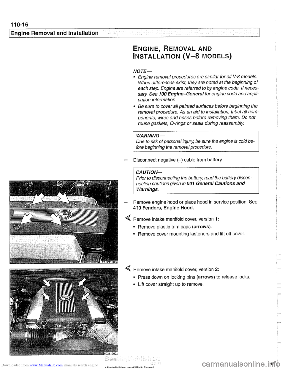
Remove
intake manifold cover, version 1:
Remove plastic trim caps (arrows).
Remove cover mounting fasteners and
lift off cover.
Remove intake manifold cover, version
2:
Press down on locking pins (arrows) to release locks
Lifl cover straight
up to remove.
Page 89 of 1002
Downloaded from www.Manualslib.com manuals search engine
- .. -.
-. Engine Removal and in=/
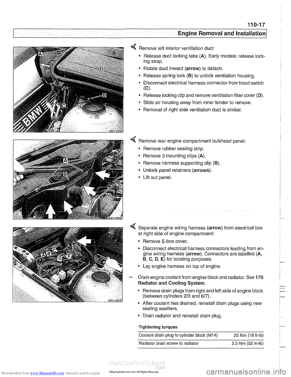
4 Remove left interior ventilation duct:
Release duct locking tabs (A). Early models: release
loclc
ing strap.
* Rotate duct inward (arrow) to detach.
Release spring
loclc (El) to unlock ventilation housing.
Disconnect electrical harness connector from hood switch
(C).
Release locking clip and remove ventilation filter cover (D).
Slide air housing away from inner fender to remove.
Removal
of right side ventilation duct is similar.
4 Remove rear engine compartment bulkhead panel:
Remove rubber sealing strip.
* Remove 3 mounting clips (A).
Remove harness supporting clip
(El).
Unlock panel retainers (arrows).
Lifl out panel.
< Separate engine wiring harness (arrow) from electrical box
at right side of engine compartment:
Remove E-box cover.
Disconnect electrical harness connectors leading from en-
gine wiring harness (arrow). Connectors are labelled (A,
El, C. D, E) for locating purposes.
Lay engine harness on top of engine.
- Drain engine coolant from engine block and radiator. See 170
Radiator and Cooling System.
Remove drain plugs from right and left side of engine
bloclc
(between cylinders 213 and 617).
Afler coolant has drained, reinstall drain plugs using new
sealing washers.
Drain radiator and reinstall drain plug.
Tightening
torques
Coolant drain plug to cylinder block (M14) 25 Nm (18 ft-ib)
Radiator drain screw to radiator 2.5
Nm (22 in-lb)
Page 90 of 1002
Downloaded from www.Manualslib.com manuals search engine
I Engine Removal and Installation
WARNING -
Use extreme caution when draining and disposing of engine
coolant. Coolant is poisonous andlethal to humans andpets.
Pets are attracted to coolant because of its sweet smell and
taste. Seek medical attention immediately if coolant is ingest-
---
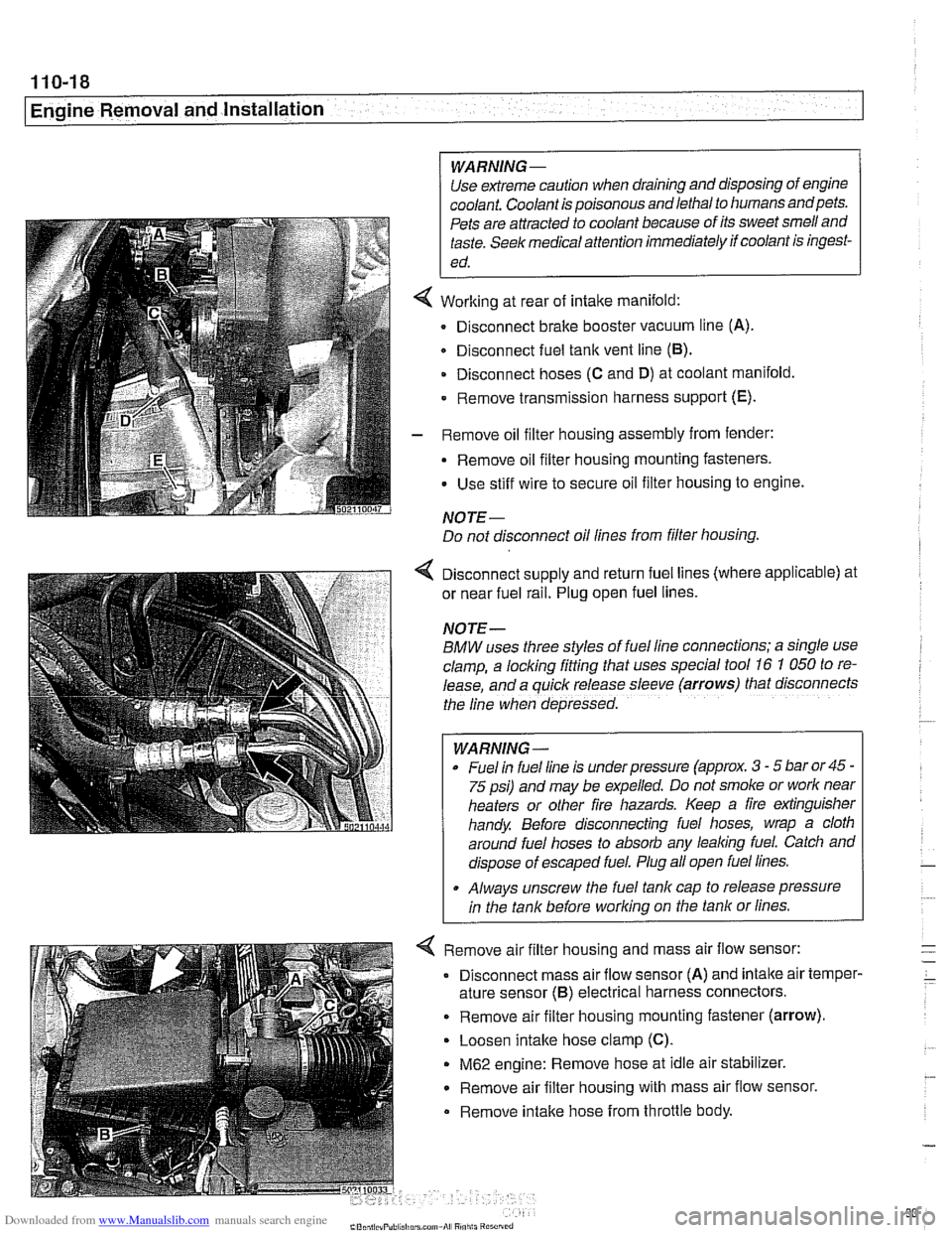
Working at rear of intake manifold:
Disconnect brake booster vacuum line (A).
Disconnect fuel tank vent line
(6).
Disconnect hoses (C and D) at coolant manifold
- Remove transmission harness support (E).
- Remove oil filter housing assembly from fender:
- Remove oil filter housing mounting fasteners.
Use stiff wire to secure oil filter housing to engine.
NOTE-
Do not disconnect oil lines from filter housing.
4 Disconnect supply and return fuel lines (where applicable) at
or near fuel rail. Plug open fuel lines.
NOTE-
BMW uses three styles of fuel line connections; a slngle use
clamp, a locking fitting that uses special tool
16 7 050 to re-
lease, and a
quiclc release sleeve (arrows) that disconnects
the line when depressed.
WARNING-
Fuel In fuel line is under pressure (approx. 3 - 5 bar or45 -
75 psi) and may be expelled. Do not smoke or worlc near
heaters or other fire hazards. Keep a fire extinguisher
handy. Before disconnecting fuel hoses, wrap a cloth
around fuel hoses to absorb any lealcing fuel. Catch and
dispose of escaped fuel. Plug all open fuel lines.
. Always unscrew the fuel tank cap to release pressure
in the tank before worlcing on the tank or lines.
< Remove air filter housing and mass air flow sensor:
Disconnect mass air flow sensor (A) and
intalte air temper-
ature sensor
(6) electrical harness connectors.
. Remove air filter housing mounting fastener (arrow).
Loosen intake hose clamp (C).
M62 engine: Remove hose at idle air stabilizer.
Remove air filter housing with mass air flow sensor.
Remove intalte hose from throttle body.