Gears BMW 540i 1999 E39 User Guide
[x] Cancel search | Manufacturer: BMW, Model Year: 1999, Model line: 540i, Model: BMW 540i 1999 E39Pages: 1002
Page 601 of 1002
Downloaded from www.Manualslib.com manuals search engine
Gearshift ~inkaael
Gearshift lever, removing
(manual transmission)
Use the accompanying illustration as a guide when removing
and installing the gearshift linkage.
- Remove shift knob by pulling knob straight off shift lever.
NOTE-
Pull up on the shift knob with about 90 lbs. of force. Do not
twist
knob or locating key can be damaged.
- Squeeze sides of shift boot to unclip from center console.
Pull boot up and off shift lever.
- Remove sound insulation at base of shift lever.
- Raise vehicle to gain access to underside of vehicle.
- --
WARNING-
Male sure the car is stable and well supported at all tfmes.
Use a professional automotwe hft orjaclc stands designed for
the purpose.
A floorjaclc 1s not adequate support.
- Remove complete exhaust system. See 180 Exhaust
System.
- Remove driveshaft. See 260 Driveshaft.
- Support transmission with transmission jack. Remove
crossmember from rear of transmission.
- Lower rear of transmission to access gearshift linkage.
CA UTIOI\C
Tilting the engine to lower the transmission can lead to
damage to various components due to lack of clearance.
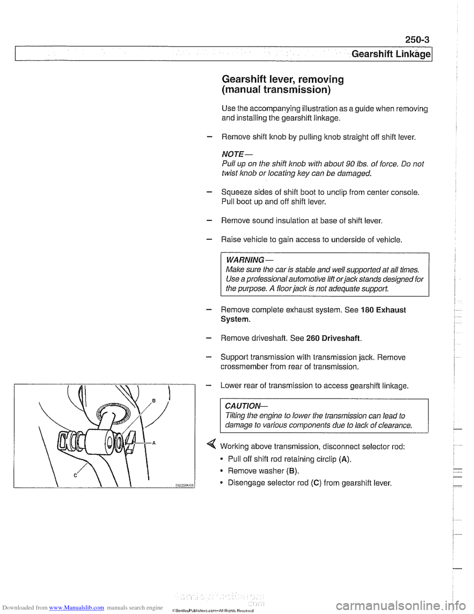
4 Working above transmission, disconnect selector rod:
* Pull off shift rod retaining circlip (A).
Remove washer (6).
Disengage selector rod (C) from gearshift lever.
Page 602 of 1002
Downloaded from www.Manualslib.com manuals search engine
250-4
I Gearshift Linkage
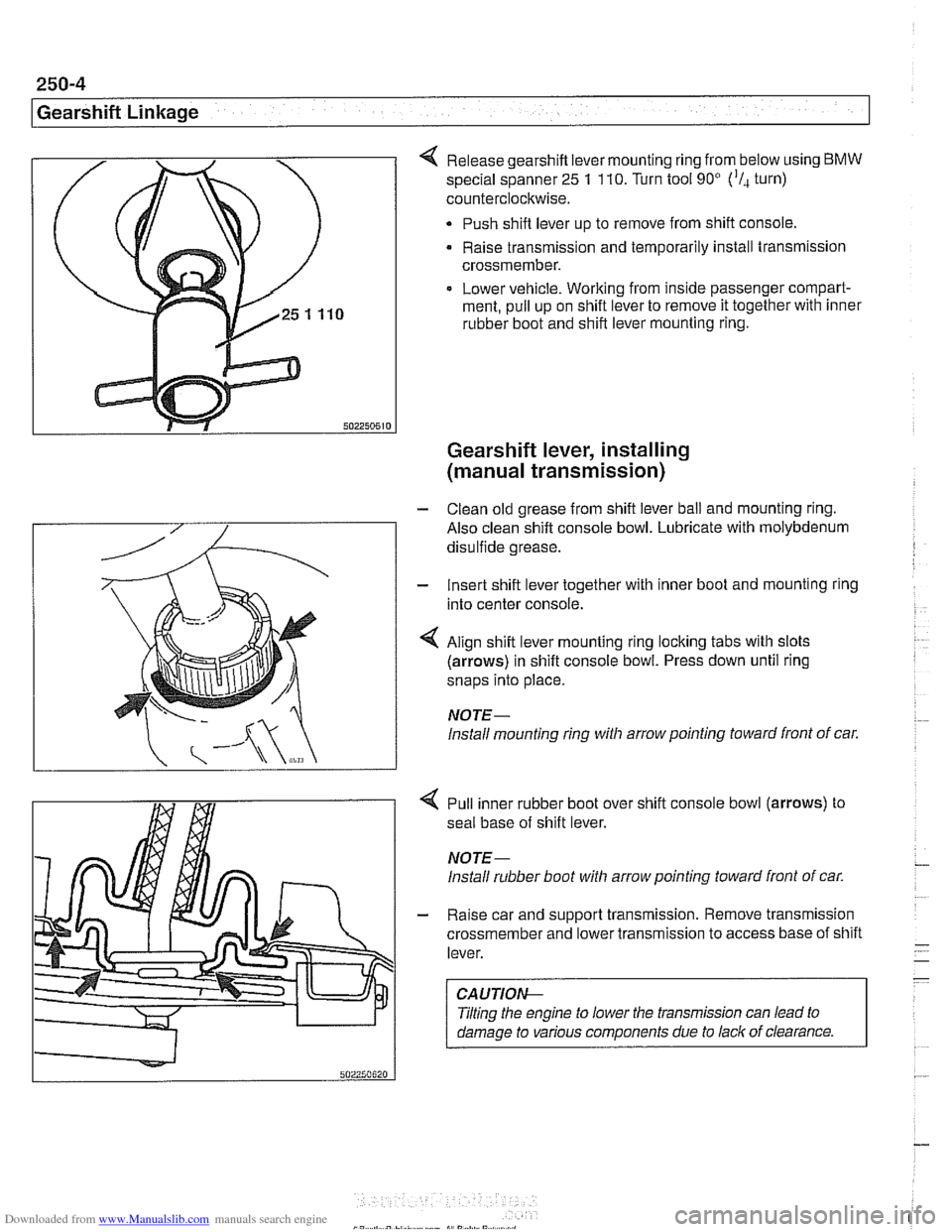
Release gearshift lever mounting ring from below using BMW
special spanner 25 1 110. Turn tool 90' ('I, turn)
counterclockwise.
Push shift lever up to remove from shift console,
Raise transmission and temporarily install transmission
crossmember.
Lower vehicle. Working from inside passenger compart-
ment, pull up on shift lever to remove it together with inner
rubber boot and shift lever mounting ring.
Gearshift lever, installing
(manual transmission)
- Clean old grease from shift lever ball and mounting ring.
Also clean shift console bowl. Lubricate with molybdenum
disulfide grease.
- Insert shift lever together with inner boot and mounting ring
into center console.
4 Align shift lever mounting ring locking tabs with slots
(arrows) in shift console bowl. Press down until ring
snaps into place.
NOTE-
lnstall mounting ring witli arrow pointing toward front of car.
4 Pull inner rubber boot over shift console bowl (arrows) to
seal base of shift lever.
NOTE-
lnstall rubber boot witli arrow pointing toward front of car.
- Raise car and support transmission. Remove transmission
crossmember and lower transmission to access base of shift
lever.
CAUTIOI\C
Tilting the engine to lower the transmission can lead to
damage to various components due to lack of clearance.
Page 603 of 1002
Downloaded from www.Manualslib.com manuals search engine
Gearshift Linkage
- Connect selector rod to shift lever. Lift transmission, install
crossmember and tighten crossmember bolts.
Install driveshaft and heat shield. See
260 Driveshaft.
Reinstall exhaust system. See 180 Exhaust System.
. Lower vehicle. Install shift boot. Push shift ltnob on lever.
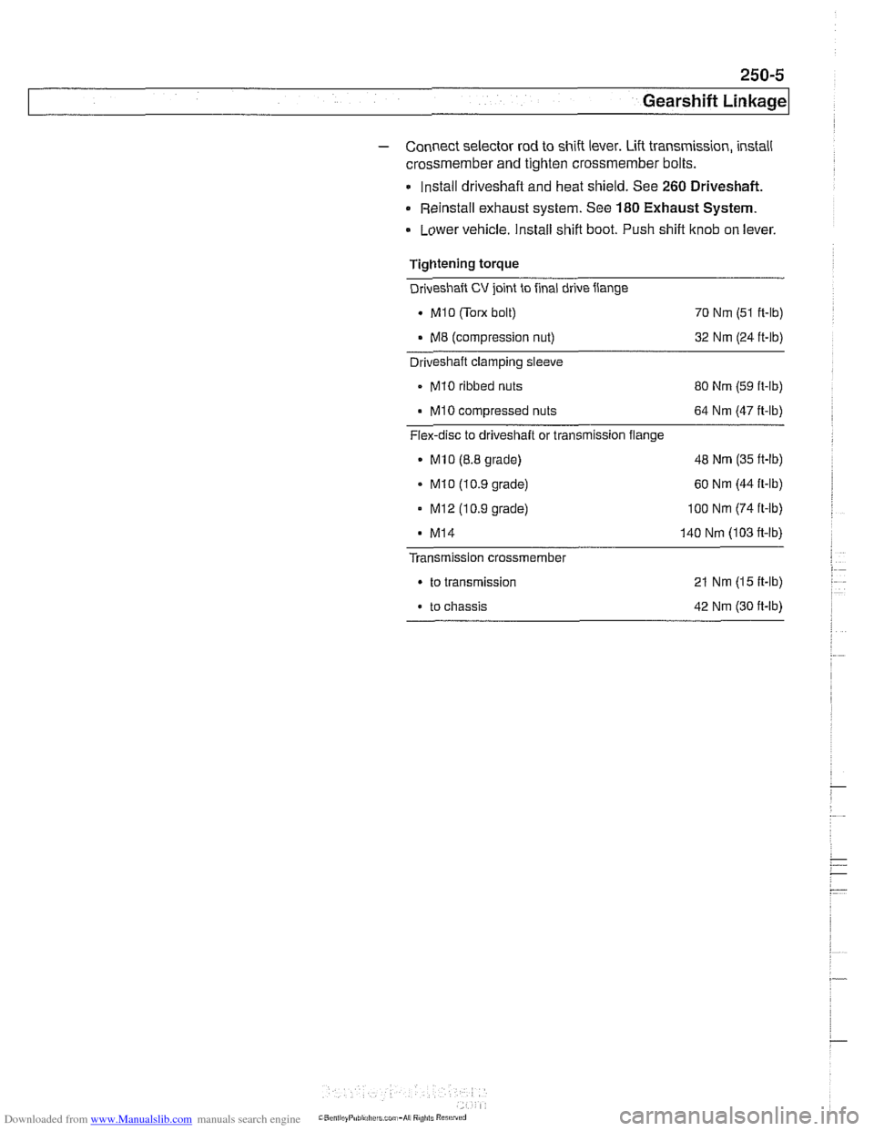
Tightening torque
Driveshaft
CV joint to final drive flange
. MI0 (Tom bolt)
70 Nm (51 ft-lb)
. M8 (compression nut) 32 Nm (24 ft-lb) - Driveshaft clamping sleeve
- MI0 ribbed nuts
80 Nm (59 ft-lb)
MI0 compressed nuts 64 Nm (47 ft-lb)
Flex-disc to driveshaft or transmission flange
MlO (8.8 grade) 48
Nm (35 ft-lb)
. MI0 (10.9 grade) 60
Nm (44 ft-lb)
- MI2 (10.9 grade) 100 Nm (74 ft-ib)
MI4 140 Nm (103 fi-lb)
Transmission crossmember
. to transmission 21 Nm (15 ft-lb)
. to chassis 42 Nm (30 ft-lb)
Page 604 of 1002
Downloaded from www.Manualslib.com manuals search engine
pearshift Linkage
~UTOMATIC TRANSMISSION
GEARSHIFT
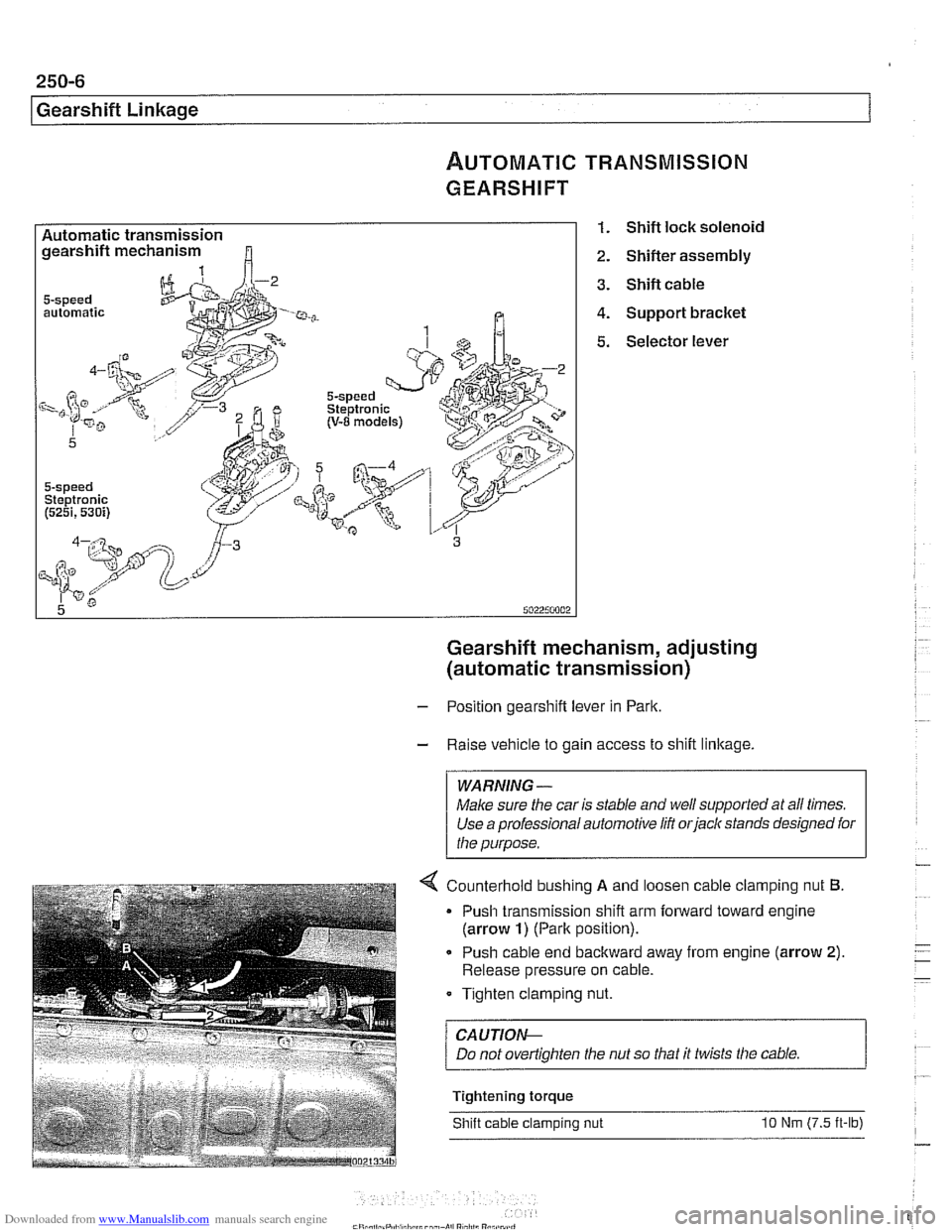
Automatic transmission gearshift mechanism
automatic
5-speed Steptronic (5251,530i)
1. Shift lock solenoid
2. Shifter assembly
3. Shift cable
4. Support bracket
5. Selector lever
Gearshift mechanism, adjusting
(automatic transmission)
- Position gearshift lever in Park.
- Raise vehicle to gain access to shift linkage.
WARNING -
Make sure the car is stable and well supported at all times.
Use a professional automotive
lift orjack stands designed for
the purpose.
4 Counterhold bushino A and loosen cable clam~ino nut 6.
Push cable end backward away from engine (arrow 2).
Release pressure on cable.
Tighten clamping nut.
/ CAUTION--
Tightening torque
Shift cable clamping nut
10 Nm (7.5 it-lb)
Page 605 of 1002
Downloaded from www.Manualslib.com manuals search engine
250-7
Gearshift ~inka~el
Automatic shiftlock, checking function (automatic transmission)
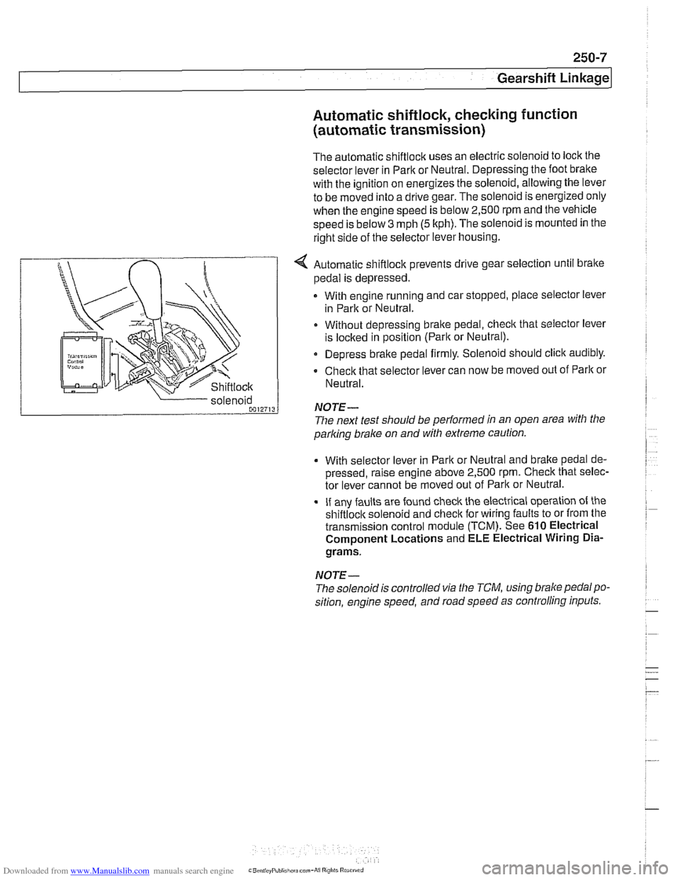
The automatic shiftlock uses an electric solenoid to lock the
selector lever in Park or Neutral. Depressing the foot bralte
with the ignition on energizes the solenoid, allowing the lever
to be moved into a drive gear. The solenoid is energized only
when the engine speed is below 2,500 rpm and the vehicle
speed is below
3 mph (5 kph). The solenoid is mounted in the
right side of the selector lever housing.
... nir r
Shiftlock
4 Automatic shiftlock prevents drive gear selection until brake
pedal is depressed.
With engine running and car stopped, place selector lever
in Park or Neutral.
Without depressing bralte pedal, check that selector lever
is
loclted in position (Parlt or Neutral).
Depress brake pedal firmly. Solenoid should click audibly.
Check that selector lever can now be moved out of
Parlt or
Neutral.
parking
brake on and with extreme caution.
solenoid
0012713
With selector
lever in Park or Neutral and bralte pedal de-
pressed, raise engine above 2,500
rpm. Check that selec-
tor lever cannot be moved out of Park or Neutral.
If any faults are found check the electrical operation of the
shiftloclt solenoid and checlt for wiring faults to or from the
transmission control module (TCM). See
610 Electrical
Component Locations and ELE Electrical Wiring
Dia-
grams.
NOTE-
NOTE-
The solenoidis controlled via the TCM, using brake pedalpo-
sition, engine speed, and road speed as controlling inputs.
The
next test should be performed in an open area with the
Page 606 of 1002
Downloaded from www.Manualslib.com manuals search engine
250-8
Gearshift Linkage
-;Ag Gate "",?it.,
Shift interlock, checking function
(automatic transmission)
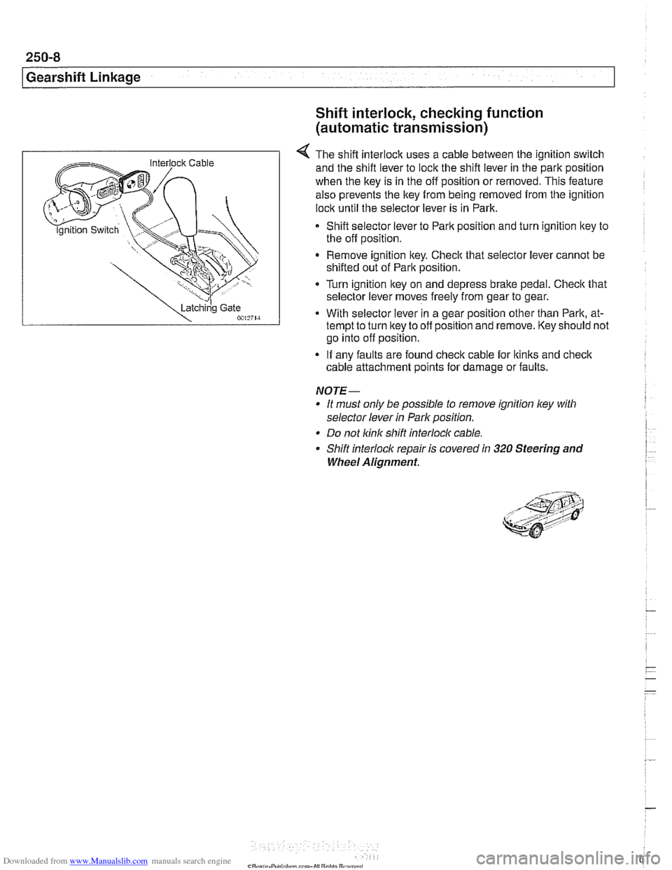
4 The shift interlock uses a cable between the ignition switch
and the shift lever to lock the shift lever in the park position
when the key is in the off position or removed. This feature
also prevents the key
from being removed from the ignition
lock until the selector lever is in Park.
Shift selector lever to Park position and turn ignition key to
the off position.
Remove ignition key. Checlc that selector lever cannot be
shifted out of Park position.
Turn ignition lkey on and depress
brake pedal. Checlc that
selector lever moves freely from gear to gear.
With selector lever in a gear position other than Park, at-
tempt to turn lkey to off position and remove. Key should not
go into off position.
If any faults are found check cable for lkinks and
check
cable attachment points for damage or faults.
NOTE-
* It must only be possible to remove ignition ley with
selector lever
in Park position.
* Do not link shift interlocl( cable.
Shift interlock repair is covered
in 320 Steering and
Wheel Alignment.
Page 880 of 1002
Downloaded from www.Manualslib.com manuals search engine
I lnterior Trim
This repair group covers interior trim removal and installation
procedures.
- Refer to the following repair groups for additional information:
250 Gearshift Linkage
41 1 Doors (interior door panels)
@ 612 Switches
620 Instruments
640 Heating and Air Conditioning [IHKA control panel!
650 Radio
721 Airbag System (SRS)
lnterior trim repairs
lnterior trim and finish panels are clipped or screwed into
place. Many of the trim retaining clips are designed
to be used
only once. When removing trim that is held in place with clips,
it is a good idea to have spare clips on hand before beginning
the job.
WARNING-
Special precautions must be observed when servicing the
BMWSupplementai Restraint System (SRS). Serious inju-
ry may result if system service is attempted by persons un-
familiar with the BMW
SRS and its approved service
procedures. BMW
speciiies that all inspection and service
should be performed by an authorized BMW
dealer.
Before performing any work involving airbags, discon-
nect the negative
() battery cable. See 721 Airbag
System (SRS).
Airbags contain a back-uppowersupply within the SRS
control module. A
5 second discharge period should be
allowed after the battery cable has been disconnected.
CAUTION-
* When working on electrical switclies or lights, always dis-
connect the negative
(-) cable from the battery and insu-
late the cable end to prevent accidental reconnection.
a Prior to disconnecting the battery, read the battery dis-
connection cautions given in
W1 General Warnings
and Cautions.
To prevent marring the trim when working on interior
components, work with plastic prying
tools or wrap the
tips of screwdrivers and pliers with tape before prying
Page 991 of 1002
Downloaded from www.Manualslib.com manuals search engine
INDEX 'tl
WARNING
Your common sense, good
judgemenl, and general alertness are
crucial to sale and successiul service
worlr. Belore attempting any work on
your
BMM be sure lo read 001
General Warnings and Cautions
and the
copyriglll page at the front 01
the manual. Review these warnings
and
caulions each lime you prepare
lo work on your BMW. Please also
read any warnings and cautions that
accompany
tile procedures in the
manual.
312-way valve (running losses)
see Fuel tank
Abbreviations, commonly used 600-14
ABS (antilock brake system)
see
Bral(es
A/C air distribution motors
see stepper motors (below)
blower final stage (resistor pack),
replacing
640-16
blower, removinglinslalling
640-1 5
compressor, replacing
640-24 condenser, replacing 64045
control panellmodule, removing1
installing
640-1 1
evaporakr, removinglinstalling 640-29
evaporator temperature sensor
640-12 expansion valve, removinglinstailing
640-27
IHKA/ IHKR system description 640-5
receiveridrier, replacing 640-26
stepper motors 640-1 3 ventilation microiilter, replacing
020-22. 640-17
see also Heating
Accelerator
iinlcage
see Maintenance
Activated carbon canister
see Fuel tank
ADS (auxiliary throttle valve)
130-57
Air compressor
330-44
Air conditioning
see
AIC
Air distribution (flap) motors
seeNC, stepper motors
Air filter see Maintenance
Air spring
300-6, 330-12
Airbag system (SRS)
2-stage
airbag 721-4
control module, replacing 721-7 driver airbag, removinglinstalling
721-8
iiead protection airbag 721-12 components 721-1 1
indicator
lighl721-4
passenger airbag, removinglinstalling
721-9 side-impact airbags crash sensor,
replacing
721-7
Airflow sensor see 130 under appropriate
fuel
injection system
Air pump
see 130 under appropriate fuel
injection system, secondary air
injection system
Air suspension
see Electronic height control
(EHC)
Alarm
see Anti-theft alarm
Alignment see
Wheei alignment
Aluminum suspension components
300-2
Antenna 650-6
Alternator see Battery, starter, alte rnator
Amplifier
650-4
Anti-theft alarm (DWA)
515-24 emergency disarming 515-31
Antifreeze (engine coolant)
see Maintenance
see also Cooling system
Antilock brake system (ABS) see Brakes
ASC see Brakes
ATF (automatic transmission fluid)
see Automatic transmission
see also Cooling systern
Automatic headlight adjustmenl
(LWR) see Lights
Automatic seat belt tensioner
720-4
Automatic shiftloclc
see
Gearshift
Automatic transmission
applications
200-3, 240-4
ATF 020-10, 200-4
capacity 240-8 checking 240-6
drainingifilling 240-7
heat exchanger 170-5
fluid pan and strainer 240-9 gearshift
see Gearshift
ID tag
200-3 range switch 610-6
removaliinstallation 240-10
steptronic see Gearshift
Auxiliary cooling fan
see
Coollng system, electric Ian
Auxiliary throttle valve (ADS)
130-57
Axle joint
see Drive axle
Back-up light switch
automatic transmission see Automatic transmission. range switch
- .~.~~~
manual transmission 230-8 -
- I
Page 996 of 1002
Downloaded from www.Manualslib.com manuals search engine
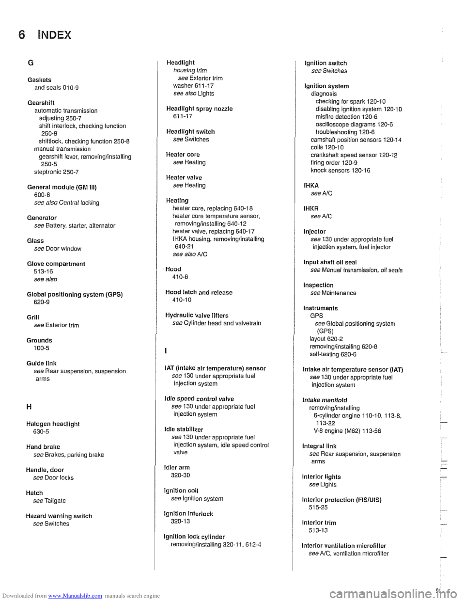
Gaskets and seals 01
0-9
Gearshift automatic transmission
adjusting
250-7
shift interiock. checkino function " 250-9
shiftloclc. checicino function 250-8 - manual transmission
gearshift lever, removingiinstalling
250-5
steptronic 250-7
General module (GM Ill)
600-8
see also Central locking
Generator see Battery, starter, alternator
Glass see Door window
Glove compartment
513-16
see also
Global positioning system
(GPS)
620-9
Grill
see Exterior trim
Grounds
100-5
Guide link
see Rear suspension, suspension
arms
Halogen headlight
630-5
Hand brake
see Brakes, pariring brake
Handle, door
see Door
locks
Hatch seeTailgate
Hazard warning switch
see Switches Headlight
housing trim
see Exterior trim
washer611-17 see also Lights
Headlight spray
nozzle
611-17
Headlight switch
see Switches
Heater core
see Heating
Heater valve
see Heating
Heating lieater core, replacing
640-18
lheater core temperature sensor,
removingiinstalling
640-12 heater valve, replacing 640-17
IHKA housing, removinglinstallin~
640-21
see also NC
Hood
410-6
Hood latch and release
410-10
Hydraulic valve lifters
see Cylinder head and valvetrain
IAT
(lntalce air temperature) sensor
see 130
under appropriate fuel
injection system
idle speed control valve
see 130
under appropriate fuel injection system
Idle stabilizer
see 130
under appropriate fuel
injection system, idie speed controi
valve
idler arm
320-30
lgnition coll
see lgnition system
lgnition interlock
320-13
lgnition lock cylinder
removingiinstalling
320-1 1. 612-4
lgnition switch
seeSwifches
Ignition system
diagnosis checking for
spark 120-10
disabling ignition system 120-10 misfire detection 120-6
oscilioscope diagrams 120.6
troubleshooting 120-6
camshaft position sensors 120-14 coils 120.10
crankshaft speed sensor 120-12 firing order 120-9
knoclc sensors 120-16
IHKA
see NC
IHKR see NC
Injector
see 130 under appropriate
fuel
injection system, luel injector
Input shaft
oil seal
see Manual transmission, oil seals
Inspection
see Maintenance
Instruments GPS see Global positioning system
(GPSI layout 6202
removingiinstalling 620-8 self-testing 620-6
Intake air temperature sensor (IAT)
see 130 under appropriate fuel
injection system
Intake manifold
removingiinstalling
6-cvlinder enoine 110-10. 113-8. 113-22 -
V-8 engine (M62) 113-56
Integral link
see Rear suspension, suspension
arms
lnterior lights
see Lights
lnterior protection
(FISIUIS) 515-25
lnterior trim
513-13
lnterior ventilation microfilter see
NC, ventilation microfiller
Page 998 of 1002
Downloaded from www.Manualslib.com manuals search engine
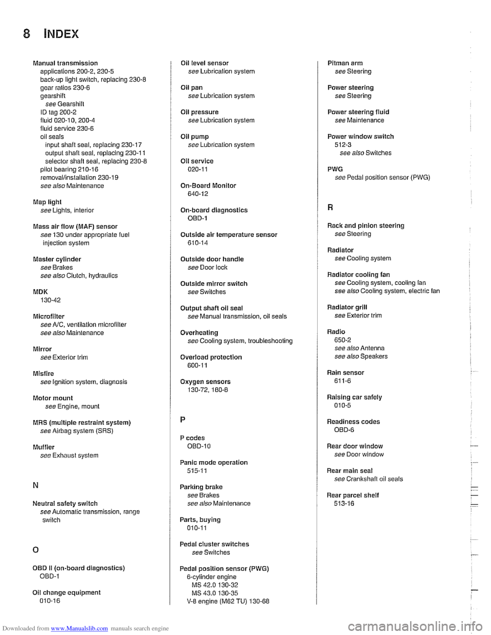
Manual transmission
applications 200-2. 230-5
back-up light switch, replacing 230-6
gear ratios 230-6
gearshift
see Gearshiit
ID tag 200-2
fluid 020-1 0. 200-4 fluid service 230-6
oil seals
input shaft seal, replacing
230-17
output shalt seal, replacing 230-1 1
selector
shaft seal, replacing 230-8 pilot bearing 210-16
removallinstallation 230-19
see also Maintenance
Map light
see Lights, interior
Mass air flow
(MAF) sensor
see 130 under appropriate fuel
injection syslem
Master cylinder
see Brakes
see also Clutch, hydraulics
MDK
130-42
Microfilter see
NC, ventilation microfilter
see also Maintenance
Mirror see Exterior trim
Misfire see Ignition syslem, diagnosis
Motor mount
see Engine,
mounl
MRS (multiple restraint system)
see Airbag system (SRS)
Muffler
see Exhaust syslem
Neutral safety switch
see Automatic transmission, range
switch
OED II (on-board diagnostics)
OED-l
Oil change equipment 010-16
Oil level sensor
see Lubrication system
Oil pan
see Lubrication system
OH pressure
see Lubrication system
Oil pump
see Lubrication system
Oil service 020-1 1
On-Board Monitor
640-12
On-board diagnostics OED-1
Outside air temperature sensor
610-14
Outside door handle
see Door
loclc
Outside mirror switch
see Switches
Output
shaft oil seal
see Manual transmission, oil seals
Overheating
see Cooling system, troubleshooting
Overload protection
600-11
Oxygen sensors
130-72, 180-8
P codes OED-10
Panic mode operation
515-11
Parking brake
see Brakes
see also Maintenance
Parts, buying
010-11
Pedal cluster switches
see Switches
Pedal position sensor (PWG)
6-cvlinder
enqine
V-8 engine (M62 TU) 130-68
Pitman arm
see Steering
Power steering
see Steering
Power steering
fluid
see Maintenance
Power window switch
512-3 see also Switches
PWG see Pedal position sensor
(PWG)
Racic and pinion steering
see Steering
Radiator see Cooling system
Radiator cooling fan seeCooling system, cooling fan
see also Cooling system, electric fan
Radiator grill
see Exterior
trim
Radio
650-2 see also Antenna
see also Speakers
Rain sensor
611-6
Raising car safely
010-5
Readiness codes
OED-6
Rear door window
see Door window
Rear main seal
see Crankshalt oil seals
Rear parcel
sheif
513-16