Ride BMW 540i 1999 E39 Owner's Manual
[x] Cancel search | Manufacturer: BMW, Model Year: 1999, Model line: 540i, Model: BMW 540i 1999 E39Pages: 1002
Page 725 of 1002
Downloaded from www.Manualslib.com manuals search engine
Rear Suspension
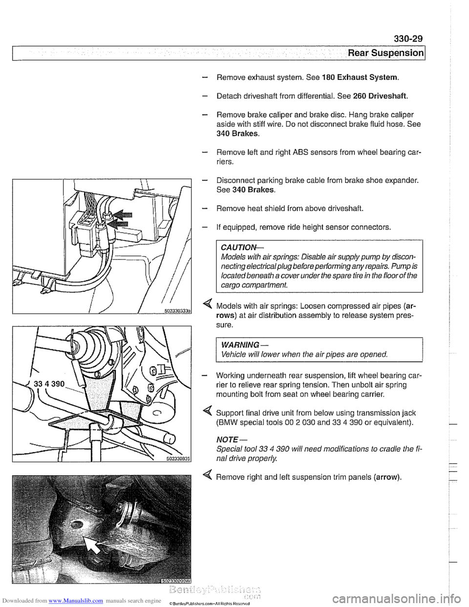
- Remove exhaust system. See 180 Exhaust System.
- Detach driveshaft from differential. See 260 Driveshaft.
- Remove brake caliper and brake disc. Hang brake caliper
aside with stiff wire. Do not disconnect brake fluid hose. See
340 Brakes.
- Remove left and right ABS sensors from wheel bearing car-
riers.
Disconnect parking brake cable from brake shoe expander.
See 340 Brakes.
Remove heat shield from above driveshaft
If equipped, remove ride height sensor connectors
CAUTION-
Models with air springs: Disable air supply pump by discon-
necting electrical plug before performing any repairs. Pump is
locatedbeneath a coverunder
thespare tire in the floorof the
carqo compartment.
Models with air springs: Loosen compressed air pipes (ar-
rows) at air distribution assembly to release system pres-
sure.
WARNING -
Vehicle will lower when the air pipes are opened. 1
- Working underneath rear suspension, lift wheel bearing car-
rier to relieve rear spring tension. Then unbolt air spring
mounting bolt from seat on wheel bearing carrier.
4 Support final drive unit from below using transmission jack
(BMW special tools 00 2 030 and 33 4 390 or equivalent).
NOTE-
Special tool 33 4 390 will need modifications to cradle the fi-
nal drive properly
4 Remove right and left suspension trim panels (arrow),
Page 740 of 1002
Downloaded from www.Manualslib.com manuals search engine
---
Rear Suspension
ELECTRONIC HEIGHT CONTROL
(EHC) COMPONENT REPLACEMENT
Sport Premium rear suspension is an option on Sport Wagon
models and standard on
1999 and later V-8 Sport Wagons.
This suspension incorporates electronic height control
(EHC)
using air springs.
With vehicle lifted off the ground,
if the rear air springs can be
compressed by hand, either the spring is defective or the sys-
tem is depressurized.
Locate
EHC faults using BMW scan tools DIS or MoDiC. EHC
description and some troubleshooting is covered in 300 Sus-
pension, Steering and Brakes-General.
Air spring replacement is covered earlier in this chapter. See
Air spring, removing and installing.
CAUTION-
Maintain high levels of cleanliness around air line connec-
tions when disassembling and assembling air suspension
components. Even
small dirt particles can cause leakage in
the pressurized system.
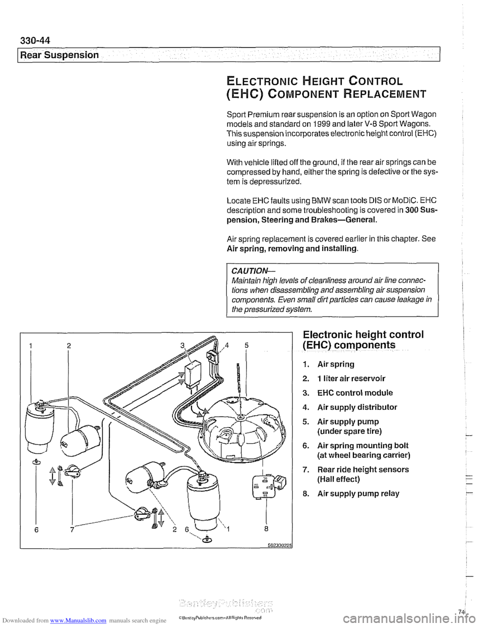
Electronic height control
(EHC) components
1. Air spring
2. 1 liter air reservoir
3. EHC control module
4. Air supply distributor
5. Airsupply pump
(under spare tire)
6. Air spring mounting bolt
(at wheel bearing carrier)
7. Rear ride height sensors
(Hall effect)
8. Air supply pump relay
Page 741 of 1002
Downloaded from www.Manualslib.com manuals search engine
-- I
I: ... . -. Rear Suspension! -- .- -
Air compressor pump relay, removing and
installing
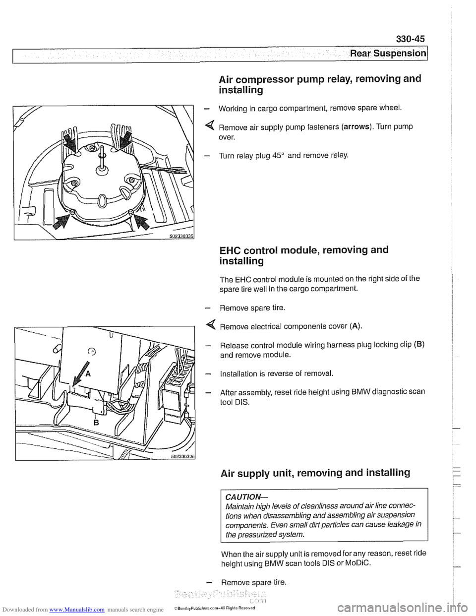
- Working in cargo compartment, remove spare wheel.
4 Remove air supply pump fasteners (arrows). Turn pump
over.
- Turn relay plug 45" and remove relay.
EHC control module, removing and
installing
The EHC control module is mounted on the right side of the
spare tire
well in the cargo compartment.
- Remove spare tire.
4 Remove electrical components cover (A).
- Release control module wiring harness plug loclting clip (B)
and remove module.
- Installation is reverse of removal.
- After assembly, reset ride height using BMW diagnostic scan
tool DIS.
Air supply unit, removing and installing
CAUTION-
Maintain high levels of cleanliness around air line connec-
tions when disassembling and assembling air suspension
components. Even small dirt particles can cause
leakage in
the pressurized system.
When the airsupply unit is removed for any reason, reset ride
height using BMW scan tools DIS or
MoDiC.
- Remove spare tire.
i~B,!n,,ayPubi.l,c~u.c~"~-A~~ R
Page 742 of 1002
Downloaded from www.Manualslib.com manuals search engine
Rear Suspension
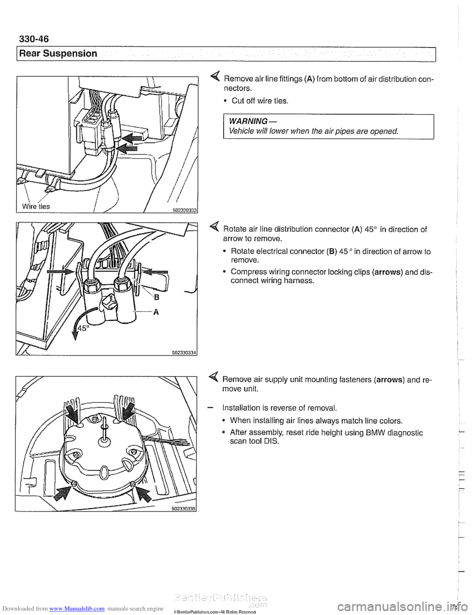
4 Remove air line fittings (A) from bottom of air distribution con-
nectors.
Cut off wire ties.
WARNING-
Vehicle will lower when the air pipes are opened.
4 Rotate air line distribution connector (A) 45" in direction of
arrow to remove.
Rotate electrical connector
(B) 45" in direction of arrow to
remove.
Compress wiring connector locking clips
(arrows) and dis-
connect wiring harness.
< Remove air supply unit mounting fasteners (arrows) and re-
move unit.
- Installation is reverse of removal.
When installing air lines always match line colors.
a After assembly, reset ride height using BMW diagnostic
scan tool DIS.
Page 743 of 1002
Downloaded from www.Manualslib.com manuals search engine
330-47
Rear suspension/
Ride height sensor, removing and installing
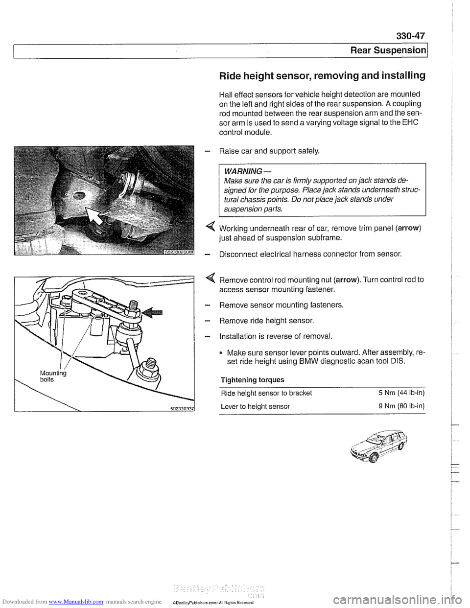
Hall effect sensors for vehicle height detection are mounted
on the
left and right sides of the rear suspension. A coupling
rod mounted between the rear suspension arm and the sen-
sor arm is used to send a varying voltage signal to the
EHC
control module.
Raise car and support safely.
WARNING-
Male sure the car is firmly supported on jaclc stands de-
signed
for the purpose. Place jaclc stands underneath struc-
tural chassis points. Do not place jaclc stands under
sus~ension Darts.
Working underneath rear of car, remove trim panel (arrow)
just ahead of suspension subframe.
Disconnect electrical harness connector from sensor.
4 Remove control rod mounting nut (arrow).Turn control rod to
access sensor mounting fastener.
- Remove sensor mounting fasteners.
- Remove ride height sensor.
- Installation is reverse of removal.
Make sure sensor lever points outward. After assembly, re-
set ride height using BMW diagnostic scan tool DIS.
Tightening torques
Ride
height sensor to bracket 5 Nrn (44 lb-in)
Lever to height sensor
9 Nrn (80 ib-in)
Page 766 of 1002
Downloaded from www.Manualslib.com manuals search engine
E39 brake system
BMW E39 models are equipped with vacuum power-assisted
four-wheel disc brakes with an integral
Antilock Brake System
(ABS). Single-piston calipers act on vented front and rear ro-
tors. A brake pad wear sensor for each axle indicates when
brake pads need replacement. The dual drum-type parking
brake system is integrated with the rear brake rotors.
Electronic braking and stability control
E39 models were introduced with Automatic Stability Control,
a computer controlled traction control system that uses the
AB5 system in conjunction with engine management controls
to control wheel spin during take-off and maintain vehicle sta-
bility while braking.
Added in the
1998 model year was Dynamic Stability Control
(DSC). This system implements wheel speed modulation
throughout all stages of driving. For example, DSC is able to
reduce understeer by applying differing amounts of braking
force to each wheel, or it can override the engine manage-
ment system during hard cornering.
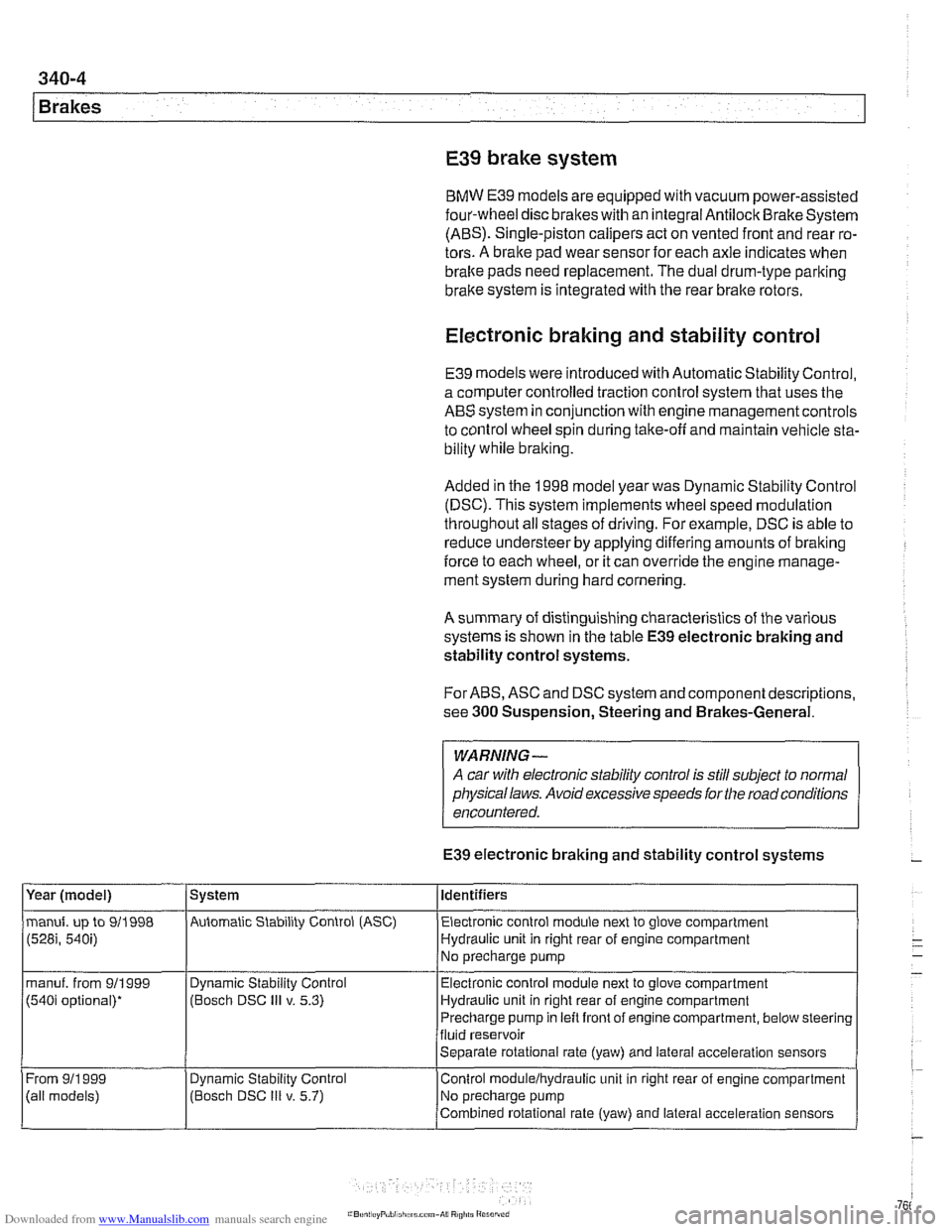
A summary of distinguishing characteristics of the various
systems is shown in the table
E39 electronic braking and
stability control systems.
For ABS, ASC and DSC system and component descriptions,
see
300 Suspension, Steering and Brakes-General.
WARNING-
A car with electronic stability control is still subject to normal
physical laws. Avoid excessive speeds for the road conditions
encountered.
E39 electronic braking and stability control systems
Year (model)
manuf. up to 911998
(528i, 540i)
manuf. from 911999
(540i optional)*
From
911 999
(ail models) System
Automatic Stability Control (ASC) Identifiers
Electronic control module next to glove compartment
Hydraulic unit in right rear of engine compartment
No precharge pump
Dynamic Stability Control
(Bosch DSC
Ill v. 5.3)
Dynamic
Stabil~ty Control
(Bosch DSC
Ill v. 5.7) Electronic
control module next to glove compartment
Hydraulic unit in right rear of engine compartment
Precharge pump in left front of engine compartment, below steering
fluid reservoir
Separate rotational rate (yaw) and lateral acceleration sensors
Control
modulelhydraulic unit in right rear of engine compartment
No precharge pump
Combined rotational rate (yaw) and lateral acceleration sensors
Page 804 of 1002
Downloaded from www.Manualslib.com manuals search engine
400-1 0
Body-General
Seats
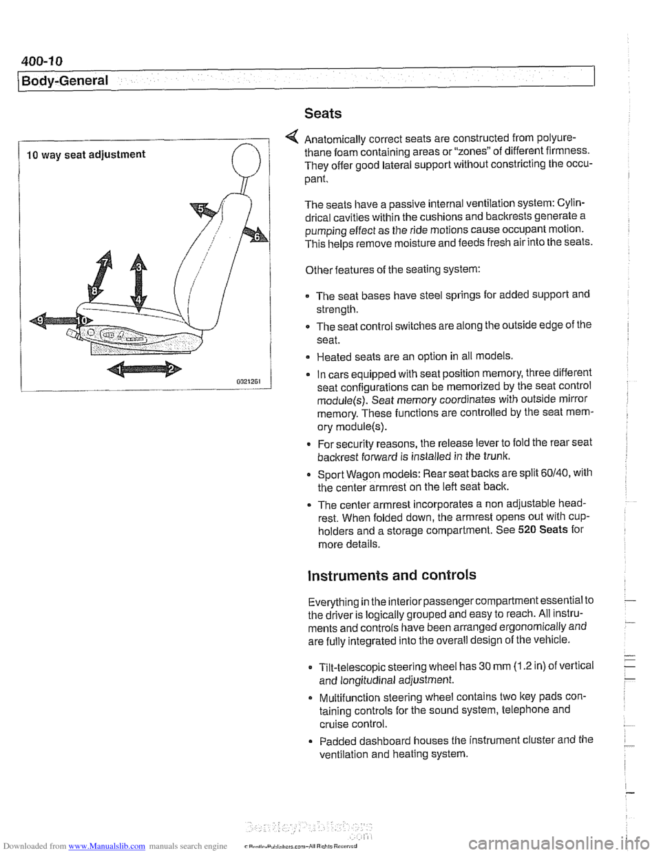
4 Anatomically correct seats are constructed from polyure-
10 way seat adjustment thane foam
containing areas or "zones" of different firmness.
They offer good lateral support without constricting the occu-
pant.
The seats have a passive internal ventilation system: Cylin-
drical cavities within the cushions and backrests generate a
pumping effect as the ride motions cause occupant motion.
This
helps remove moisture and feeds fresh air into the seats.
Other features of the seating system:
The seat bases have steel springs for added support and
strength.
The seat control switches are along the outside edge of
the
seat.
Heated seats are an option in all models
In cars equipped with seat position memory, three different
seat confiaurations can be memorized by the seat control
module(s): Seat memory coordinates with outside mirror
memory. These functions are controlled by the seat mem-
ory
module(s).
* For security reasons, the release lever to fold the rear seat
backrest forward is installed in the trunk.
Sport Wagon models: Rear seat
baclts are split 60140, with
the center armrest on the left seat back.
The center armrest incorporates a non adjustable head-
rest. When folded down, the armrest opens out with
cup-
holders and a storage compartment. See 520 Seats for
more details.
instruments and controls
Everything in the interior passengercompartment essential to
the driver is logically grouped and easy to reach. All instru-
ments and controls have been arranged ergonomically and
are fully integrated into the overall design of the vehicle.
Tilt-telescopic steering wheel has
30 mm (1.2 in) of vertical
and longitudinal adjustment.
Multifunction steering wheel contains two
ltey pads con-
taining controls for the sound system, telephone and
cruise control.
Padded dashboard houses the instrument cluster and the
ventilation and heating system.
Page 900 of 1002
Downloaded from www.Manualslib.com manuals search engine
51 5-6
(Central Locking and Anti-Theft
Each rear door is equipped with the child lock-out lever, pre-
venting the door from being opened from the inside regard-
less of loclc button position.
Starting with models produced afler
911997, the General
Module and electronic immobilizer (EWS) interface via the
K-
Bus to monitor double lock status and to initiate double loclc
override. This feature allows the doors to be opened from the
inside if a key accepted by EWS is switched on in the ignition.
See Single lock and double lock function.
The door loclc buttons are mechanically uncoupled from the
actuators when locked. The remote keyless entry system
(FZV) is standard equipment. This allows for elimination of
the passengers side door
loclt cylinder.
Another function of the locking system is the
sofl close trunk
(SCA) system, where applicable.
Single lock and double lock function
(2000 and later models)
On models produced after
911999, each door lock actuator in-
corporates two motors:
Single lock motor controls the mechanical loclc mechanism
when the central lock switch is pressed to single loclc the
vehicle. The loclc mechanism is fully locked at this point but
can stil. be openeo from
the interor by pulng the appropri-
are interior door nandle lwce or by pressing rhe central
lock switch again. When single
lock'function is activated,
the fuel filler flap actuator is not locked.
Double lock motor, also known as central arrest, is activat-
ed only when the vehicle is locked from the outside at the
driver's door lock with a key or when the GM receives a
lock request from the remote entry (FZV) system. In this
case the double lock motor is activated simultaneously
with the single lock motor. The function of the double loclc
motor is to mechanically offset an internal rod in the loclc
actuator, disabling it from unlocking the vehicle from the in-
terior. This prevents the doors from being unloclted by any
means except from an unlock request at the driver's door
or via the FZV remote key.
Lock cylinder safety
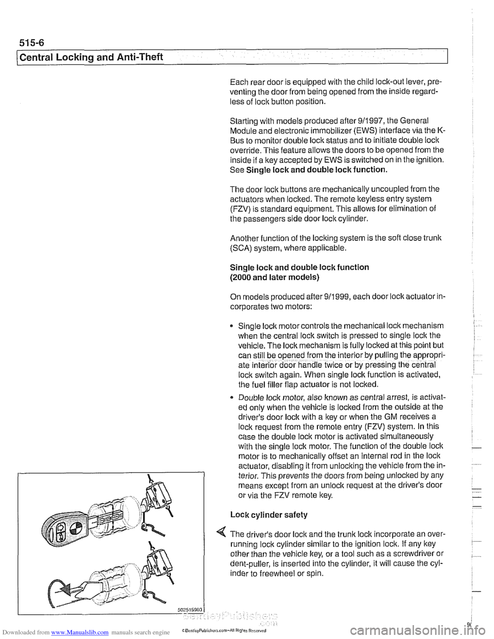
4 The driver's door loclc and the trunk loclc incorporate an over-
running loclc cylinder similar to the ignition lock. If any key
other than the vehicle key, or a tool such as a screwdriver or
dent-puller, is inserted into the cylinder, it will cause the cyl-
inder to freewheel or spin.
Page 995 of 1002
Downloaded from www.Manualslib.com manuals search engine
INDEX 5
WARNING
Your common sense, good
judgement, and general alerlness are
crucial lo
safe and successful service ivork. Before attempling any work on
your
BMW be sure lo read 001
General Warnings and Cautions
and the copyright page at the
fronl of
Ihe manual. Review these warnings
and
cautions each lime you prepare
to work on your BMW Please also
read any warnings and cautions tliat
accompany Nie procedures in the
manual.
Exhaust manifold see Exhaust system
Exhaust system diagrams
180.1 1
exhaust manifolds, removinglinstalling
180-4 muifier, replacing 180-8
oxygen sensors 180-8
and catalytic converter 020-1 9
see also Fuel injection
removinglinstalling 180-2
see also Maintenance
Expansion tank
see Cooling system
Expansion valve
see
NC
Exterior lighting
see
Lights
Exterior trim
BMW emblem
(Roundel), removing1
installing
510-13 body side molding, replacing 510.13
grill, removinglinsialiing 510-14
headlight housing trim, removing1
installing 510-14
outside mirror
510-2
EWS (electronic immobilization)
515-21 ring antenna,
iemovinglinstaiting
320-1 1
Fan see Cooling system Fault
codes
OBD-2
storage
100-4. 600.10
Fender
front, rernovinglinstailing
410-2
Filters see Maintenance
Final drive
lubricant
speciiicatiorls 020-9
mounh, replacing 331-12
oil level 020-26. 331-6
removinglinslalling 331-5 seals 331-7
Firing order
see Ignition system
FtS
see Interior protectiorl
Flex disc
see Driveshaft
Fluids and lubricants see Maintenance
Flywheel removinglinstalling 210-13
Fogllght
see Lights
Front centering guide see Driveshatt
Front oil seal
see
Crankshaft oil seals
Front suspension control arm
310-12 description 300-2
ride height 300-14
stabilizer bar, removinglinstalling
310-21
strutslsprings 31
0-4
tension strut 310-16
thrust arm 310-12 variations 310-4
wheel bearing 310-18
see also Maintenance
Fuel filter
see Maintenance
Fuet injection applications 130-2
Bosch M5.2, M5.2.1 130-46
Bosch ME 7.2 130-66 fuel delivery
see 130 under appropriate iuel
injection system
see also Fuel pump
see also
Fuet tank
oxygen sensors
130-72, 180-8
Siemens MS 41.1 130-7 Siemens MS 42.0. MS 43.0 130-23
Fuel injector
see 130 under appropriate fuel
injection system
Fuel level sender
160-15
see also Fuei pump
Fuel pressure
160-10
see also Fuel pump
Fuel pump
160-3
electrical circuit, testino 160-7
1
removinglinstalling (includes right side
iuel levei sender) 160-15
siphon pump, removinglinstaliing
160-19
troubleshooting 160-6 see also Fuel tank
Fuel rail
see 130 under appropriate iuel
injection system
Fuei supply
130-6
see also Fuei pump
see also
Fuet lank
Fuel
tank
312-way valve (running losses.
removinglinstalling
160-24 carbon canister 160-24
draining 160-20
evaporative control system 160-3
expansion tank, removinglinstalling
160-23
I
leak detection unit (LDP or DM-TL),
rernovinoiinstallino 160-24
level senier 160-15
removinglinstalling 160-21
Fuse locations
610-29
RV (remote entry)
see Central
locl(ing
Fan clutch
see Cooling system, cooling fan
Page 999 of 1002
Downloaded from www.Manualslib.com manuals search engine
INDEX 9
WARNING
Your common sense, good judgemenl, and general alerlness are
crucial lo seie end successful service
ivork. Beiore attempting any work on
your
BMW be sure to read 001
General Warnings and Cautions and llle copyright page at lhe iron1 of
the manual. Review Niese warnings
and caulions each lime you prepare
lo work on your BMW Please also
read any warnings and caulions lllal accompany the procedures in the
manual.
Rear suspension
ball joints
330-19
bushings 330-13
control arms
seesuspension arms, below
description
300-5
electronic height control (EHC)
330-44
ride height 300-14 ride height sensor 330-46
shoclr absorbers end springs 330-9
stabilizer bar 330-42
struts and springs 330-5 subframe 330.13
suspension arms 330-13
variations 330-4 wheel bearing, replacing 330-32
see also Maintenance
see also Drive axles
see also Final drive
Rear window (Sport Wagon)
see
Tailgate
Rear window defroster 610-17
Receiverldrter
see NC
Relay positions
see Electrical component tocations
table 610-3
Remote entry (FZV)
see Central locking
Reversing light switch
see
Baclc-up light switch
Ride height
300-14
Ride height sensor
see Rear suspension
Ring antenna
see EWS (electronic immobilizalion)
Rotor
see Brakes
Roundel see Exterior trim
Running tosses
(312-way) valve
see Fuel
tenlr
SCA (soft close)
seeTailgate, soft close
see also Trunk lid. soft close
Scan tools
OED-3
Seals gaskets and 010-9
see also Crankshaft seals
Seat front,
removing/instelling 520-10
memory system 520-4 rear 520-13
see also Seat belt
Seat beit front 720-4
rear 720-8
troubleshooting 7202
see also Maintenance
Secondary air injection
see 130 under appropriate
iuel
injection system
Selector shaft seat
see Manual transmission, oil
Seals
Self-adjusting ctulch (SAC)
see Clutch, variations
Service indicator see Maintenance
Shift interlock see Gearshift
Shift lever
see
Gearshift
Shift linkage see Gearshift
Shiftlock see Gearshilt
Shack absorber see Rear suspension
/ Side turn signal assembly
see Lights
Sill trim panel
411-10
Slave cylinder
see Clutch, lhydraulic
Steep mode
600-1 1
Soft close
(SCA) see Tailgate
see also
Trunk lid
Solenoid 121-23
Sound system
650-2
Spare parts kit
010-21
Spark plugs
see Maintenance
Speakers
650-4
Specifications, fluid
020-4
Sport wagon
400-4
Springs
see Front suspension
see also Rear suspension
SRS (supplemental restraint system)
see
Airbag system (SRS)
Stabilizer bar see Front suspension
see also Rear suspension
Starter see Battery, starter, alternator