boot BMW 540i 1999 E39 Owner's Manual
[x] Cancel search | Manufacturer: BMW, Model Year: 1999, Model line: 540i, Model: BMW 540i 1999 E39Pages: 1002
Page 602 of 1002
Downloaded from www.Manualslib.com manuals search engine
250-4
I Gearshift Linkage
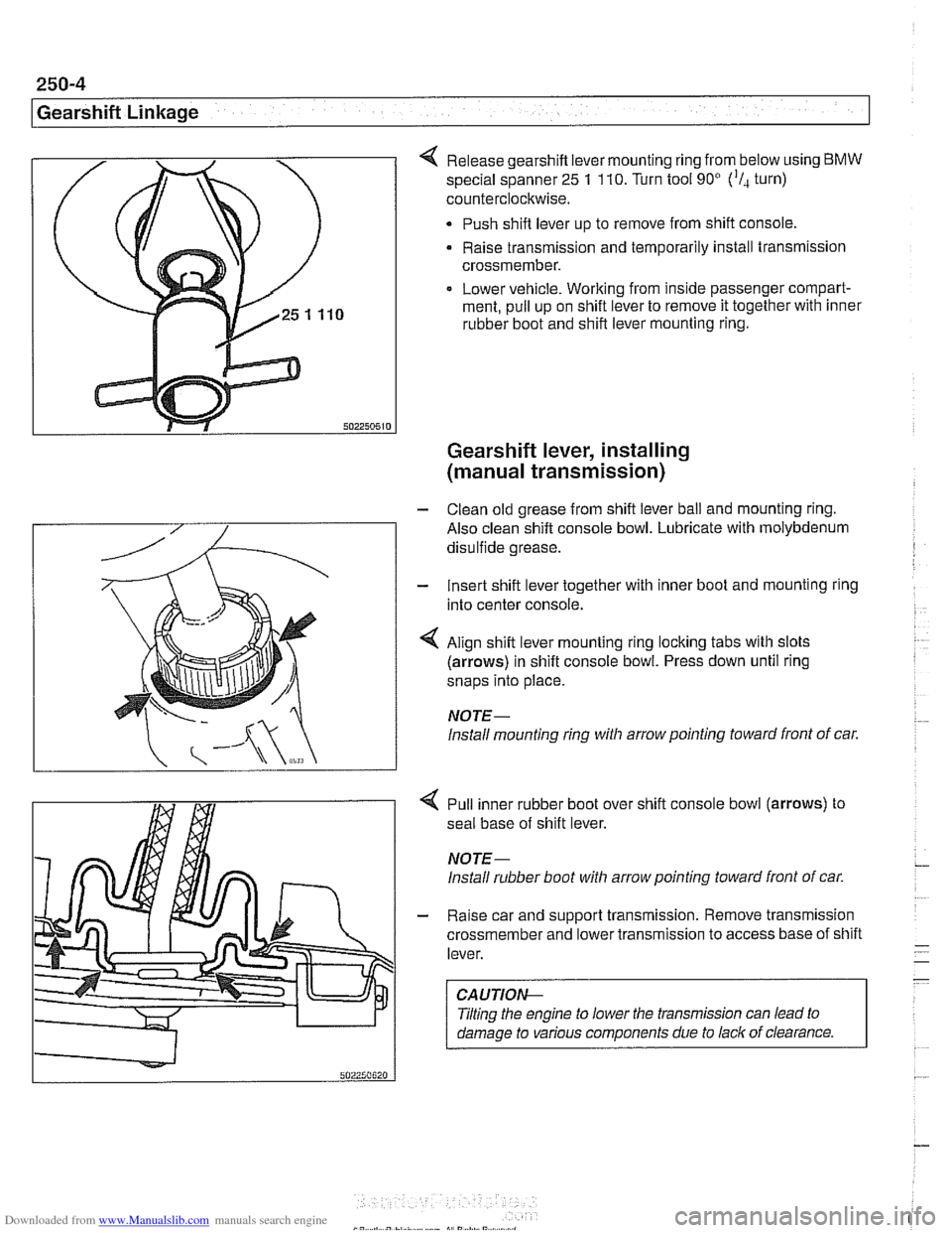
Release gearshift lever mounting ring from below using BMW
special spanner 25 1 110. Turn tool 90' ('I, turn)
counterclockwise.
Push shift lever up to remove from shift console,
Raise transmission and temporarily install transmission
crossmember.
Lower vehicle. Working from inside passenger compart-
ment, pull up on shift lever to remove it together with inner
rubber boot and shift lever mounting ring.
Gearshift lever, installing
(manual transmission)
- Clean old grease from shift lever ball and mounting ring.
Also clean shift console bowl. Lubricate with molybdenum
disulfide grease.
- Insert shift lever together with inner boot and mounting ring
into center console.
4 Align shift lever mounting ring locking tabs with slots
(arrows) in shift console bowl. Press down until ring
snaps into place.
NOTE-
lnstall mounting ring witli arrow pointing toward front of car.
4 Pull inner rubber boot over shift console bowl (arrows) to
seal base of shift lever.
NOTE-
lnstall rubber boot witli arrow pointing toward front of car.
- Raise car and support transmission. Remove transmission
crossmember and lower transmission to access base of shift
lever.
CAUTIOI\C
Tilting the engine to lower the transmission can lead to
damage to various components due to lack of clearance.
Page 603 of 1002
Downloaded from www.Manualslib.com manuals search engine
Gearshift Linkage
- Connect selector rod to shift lever. Lift transmission, install
crossmember and tighten crossmember bolts.
Install driveshaft and heat shield. See
260 Driveshaft.
Reinstall exhaust system. See 180 Exhaust System.
. Lower vehicle. Install shift boot. Push shift ltnob on lever.
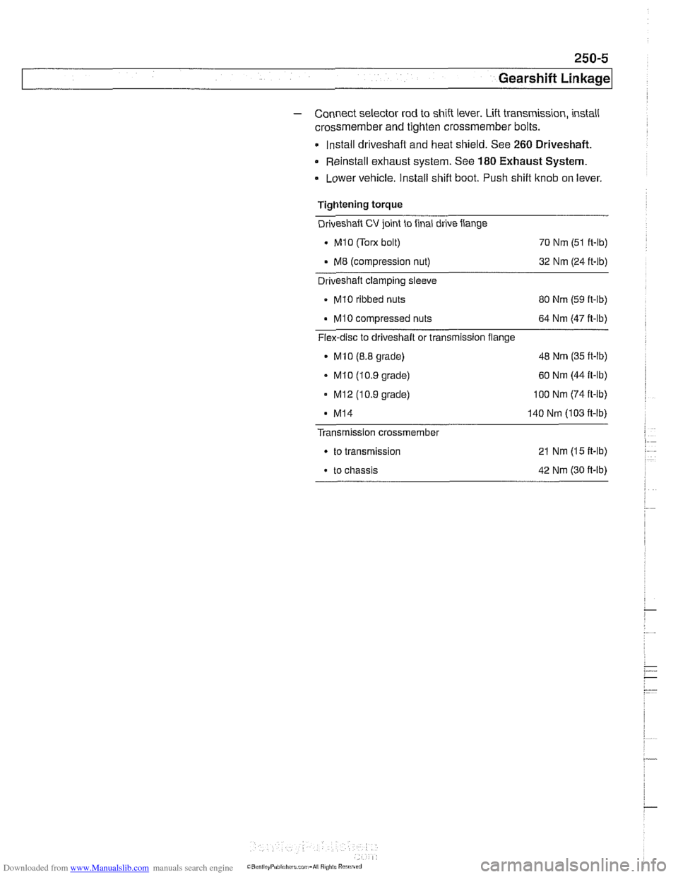
Tightening torque
Driveshaft
CV joint to final drive flange
. MI0 (Tom bolt)
70 Nm (51 ft-lb)
. M8 (compression nut) 32 Nm (24 ft-lb) - Driveshaft clamping sleeve
- MI0 ribbed nuts
80 Nm (59 ft-lb)
MI0 compressed nuts 64 Nm (47 ft-lb)
Flex-disc to driveshaft or transmission flange
MlO (8.8 grade) 48
Nm (35 ft-lb)
. MI0 (10.9 grade) 60
Nm (44 ft-lb)
- MI2 (10.9 grade) 100 Nm (74 ft-ib)
MI4 140 Nm (103 fi-lb)
Transmission crossmember
. to transmission 21 Nm (15 ft-lb)
. to chassis 42 Nm (30 ft-lb)
Page 615 of 1002
Downloaded from www.Manualslib.com manuals search engine
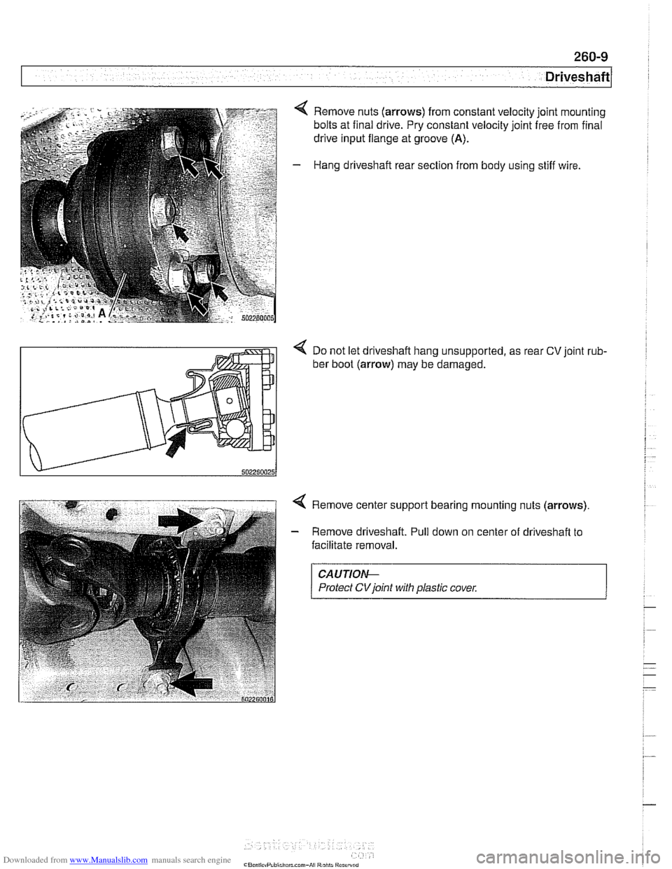
4 Remove nuts (arrows) from constant velocity joint mounting
bolts at final drive. Pry constant velocity joint free from final
drive input flange at groove
(A).
- Hang driveshaft rear section from body using stiff wire.
< Do not let driveshaft hang unsupported, as rear CV joint rub-
ber boot (arrow) may be damaged.
4 Remove center support bearing mounting nuts (arrows)
- Remove driveshaft. Pull down on center of driveshaft to
facilitate removal.
CAUTIOI\C
Protect CVjoint with plastic cover.
Page 620 of 1002
Downloaded from www.Manualslib.com manuals search engine
260-14
Driveshaft
Constant velocity (CV) joint, replacing
The CV joint at the rear of the driveshaft is available from
BMW as a separate part.
- Remove complete driveshaft as described earlier in this
section.
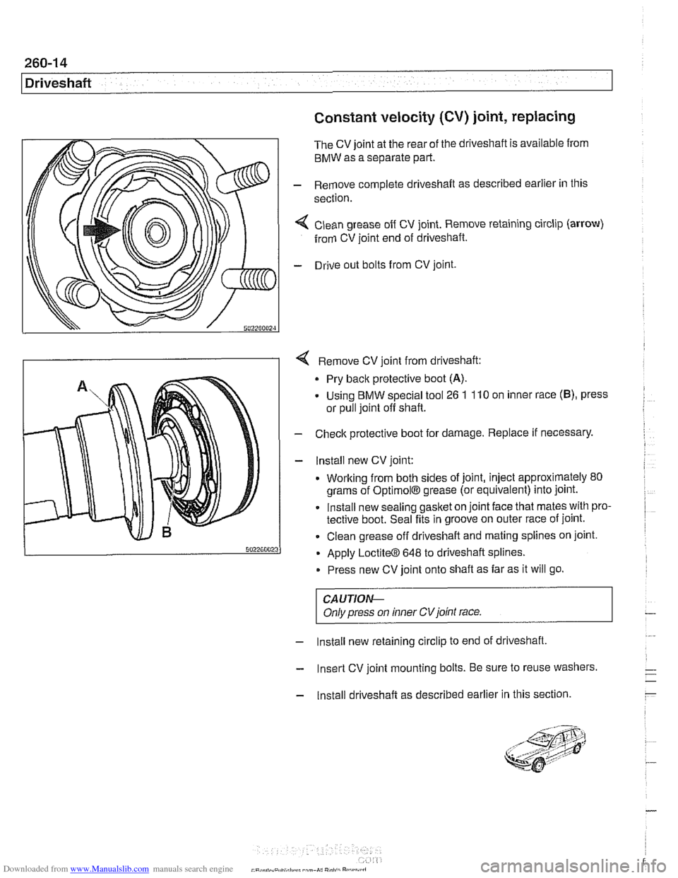
< Clean grease off CV joint. Remove retaining circlip (arrow)
from CV joint end of driveshaft.
- Drive out bolts from CV joint.
4 Remove CV joint from driveshaft:
Pry back protective boot
(A).
- Using BMW special tool 26 1 110 on inner race (B), press
or pull joint off shaft.
- Check protective boot for damage. Replace if necessary.
- lnstall new CV joint:
. Working from both sides of joint, inject approximately 80
grams of
OptimolB grease (or equivalent) into joint.
Install new sealing gasket on joint face that mates with pro-
tective boot. Seal fits in groove on outer race of joint.
Clean grease off driveshaft and mating splines on joint.
Apply
LoctiteO 648 to driveshaft splines.
Press new CV joint onto shaft as far as it will go.
CAUTIOI\C
Only press on inner CVjoint race.
- Install new retaining circlip to end of driveshaft,
- Insert CV joint mounting bolts. Be sure to reuse washers.
- Install driveshaft as described earlier in this section.
Page 645 of 1002
Downloaded from www.Manualslib.com manuals search engine
31 0-9
Front Suspension
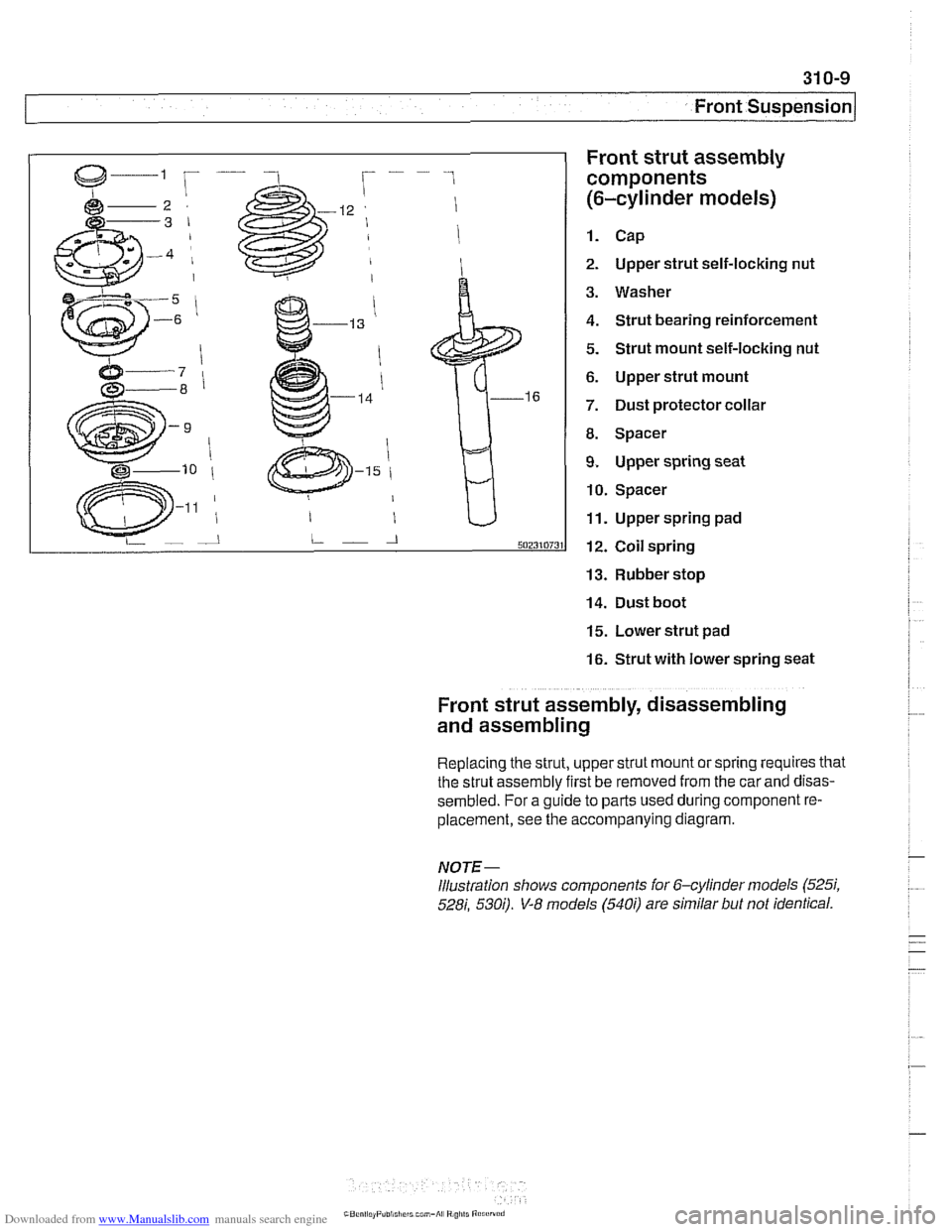
Front strut assembly
components
(6-cylinder models)
1. Cap
2. Upper strut self-locking nut
3. Washer
4. Strut bearing reinforcement
5. Strut mount self-locking nut
6. Upper strut mount
7. Dust protector collar
8. Spacer
9. Upper spring seat
10. Spacer
11. Upper spring pad
12. Coil spring
13. Rubber stop
14. Dust boot
15. Lower strut pad
16. Strut with lower spring seat
Front strut assembly, disassembling
and assembling
Replacing the strut, upper strut mount or spring requires that
the strut assembly first be removed from the car
and disas-
sembled. For a guide to parts used during component re-
placement, see the accompanying diagram.
NOTE-
Illustration shows components ior 6-cylinder models (525i,
528i, 530;). V-8 models (540i) are similar but not identical.
Page 646 of 1002
Downloaded from www.Manualslib.com manuals search engine
31 0-1 0
Front Suspension
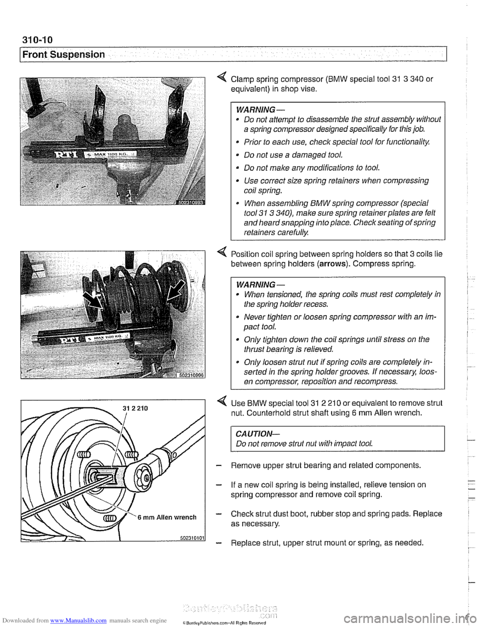
4 Clamp spring compressor (BMW special tool 31 3 340 or
equivalent) in shop vise.
WARNING-
* Do not attempt to disassemble the strut assembly without
a spring compressor designed specifically for this job.
Prior to each use,
checlc special tool for functionality.
Do not use a damaged tool.
Do not make any modifications to tool. Use correct size spring retainers when compressing
coil spring.
I When assembling BMW spring compressor (special
tool
31 3 340), make sure spring retainerplates are felt
and heard snapping into place. Check seating of spring
retainers carefully.
Position coil spring between spring holders so that
3 coils lie
between spring holders
(arrows). Compress spring.
WARNING -
When tensioned, the spring coils must rest completely in
the spring holder recess.
Never tighten or loosen spring compressor with an im-
pact tool.
Only tighten down the coil springs until stress on the
thrust bearing is relieved.
a Only loosen strut nut if spring coils are completely in-
serted in the spring holder grooves. If
necessarx loos-
en compressor, reposition and recompress.
Use
BMW special tool 31 2 21 0 or equivalent to remove strut
nut. Counterhold strut shaft using
6 mm Allen wrench.
CAUTION-
Do not remove strut nut with impact tool.
Remove upper strut bearing and related components.
If a new coil spring is being installed, relieve tension on
spring compressor and remove coil spring.
Check strut dust boot, rubber stop and spring pads. Replace
as necessary.
Replace strut, upper strut mount or spring, as needed
Page 659 of 1002
Downloaded from www.Manualslib.com manuals search engine
1 320 Steering and Wheel Alignment
General ........................... .32 0.2
Special tools
........................ .32 0.2
Steering system
..................... .32 0.4
Steering system variations
............. .32 0.5
Steering system warnings and cautions
... .32 0.6
Steering Wheel .................... .32 0.7
Steering wheel. removal and installation
.. .32 0.7
Steering Column ................. .32 0.1 0
Steering column components .......... .32 0.10
Steering column trim, removing
and replacing
...................... .32 0.10
lgnition switch ring antenna (EWS).
removing and installing
............... .32 0.1 1
lgnition lock cylinder.
removing and installing
............... .32 0-1 1
Steering column lock. removing
and installing
....................... .32 0.12
lgnition
interloclc cable. removing and installing
(models with automatic transmission)
... .32 0.13
Interlock cable. adjusting
(models with automatic transmission)
... .32 0.14
Steering column. removing and installing
. .32 0.14
Steering column adjustment motors.
removing and installing
............... .32 0.16
Power Steering Pump ............. .32 0.17
Power steering pump. removing
and installing
....................... .32 0.1 7
Power steering system.
bleeding and filling
.................. .32 0.18
Rack and Pinion Steering
(6-cylinder models)
............... 320-19
Rack and pinion steering components
(6-cylinder models)
.................. 320-1 9
Steering rack. removing and installing
.... 320-19
Steering
rack boot. replacing ........... 320-22
Tie rod (outer). replacing
.............. 320-22
Tie rod (inner). replacing
.............. 320-23
Steering Gearbox (V-8 models) .... 320-24
Steering gearbox system components
. .
(V-8 models) ....................... 320-24
Steering gearbox, removing and installing 320-25
Pitman arm. removing and installing ..... 320-28
Pitman arm. adjusting ................ 320-29
Steering idler arm. removing
and installing
....................... 320-30
Idler arm bushing. replacing ........... 320-31
Center tie rod. replacing
.............. 320-32
Wheel Alignment .................. 320-33
Camber
........................... 320-33
Caster
............................ 320-33
Front toe and toe difference angle
....... 320-34
Reartoe ........................... 320-34
Preparing for alignment
............... 320-35
Alignment specifications tables
......... 320-35
Page 662 of 1002
Downloaded from www.Manualslib.com manuals search engine
I Steerina and Wheel Alianment
Steering
system
Two types of steering gear are used in the E39 series models.
6-cylinder
(5251, 528i and 530i) models are equipped with
rack and pinion steering. The steering rack is mounted to
an aluminum subframe.
V-8
(540i) models are equipped with a recirculating ball
and nut steering gearbox mounted to a steel subframe.
At low speeds, maximum power assist is provided to ease
parking and city driving. At high speeds, assist is reduced to
ensure stability. The power steering system varies assist
based on engine speed.
Power boost for the steering is provided by an engine-driven
hydraulic pump. A hydraulic control valve is used to control
boost pressure.
The steering wheel connects to the steering gear via an ad-
justable steering column which incorporates a rubber cou-
pling ("guibo") to dampen vibration and noise.
Power steering fluid is supplied from the fluid
reservoir to the
pump and to the steering gear via rubberlmetal hoses.
The return line from the steering gear to the
reservoir loops
into the airstream in front of the radiator and connects to the
steering fluid cooler. The fluid cooler is attached to a cassette
which also includes cooling coils for engine oil, transmission
fluid and AIC condenser.
The steering gear requires no maintenance other than align-
ment and periodic inspection for worn components. Inspect
rubber rack boots
(rack and pinion system) and tie-rod end
boots periodically for tears or damage. Replace
if necessary.
-
NOTE-
The airbag system is traditionally referred to as Supplemen-
tal Restraint System (SRS). The
BMW versfon of SRS used
m the E39 models is known as the Multiple Restraint System - (MRS). - -
Page 677 of 1002
Downloaded from www.Manualslib.com manuals search engine
i Steering and Wheel Alignment
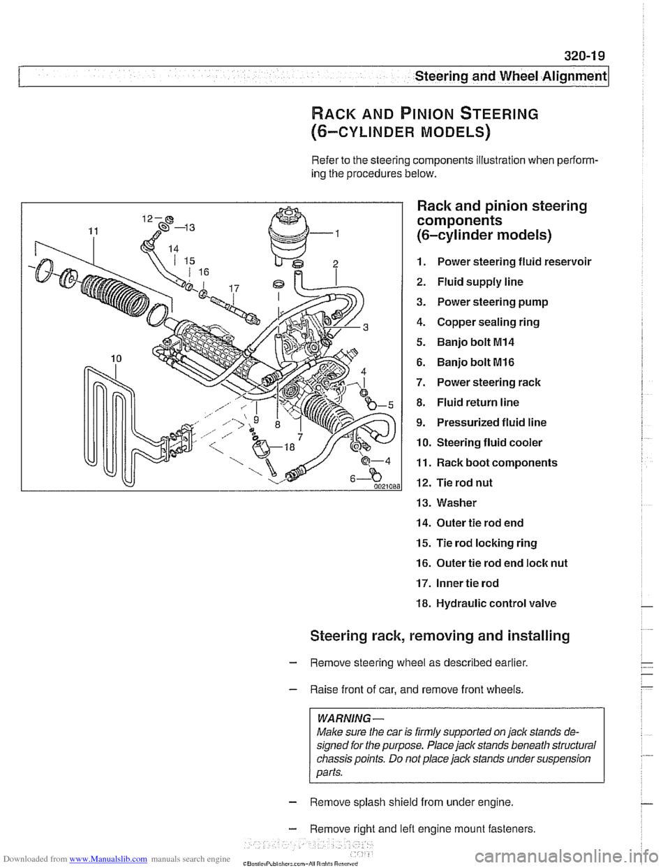
RACK AND PINION STEERING
(6-CYLINDER MODELS)
Refer to the steering components illustration when perform-
ing the procedures below.
Rack and pinion steering
components
(6-cylinder models)
1. Power steering fluid reservoir
2. Fluid supply line
3. Power steering pump
4. Copper sealing ring
5. Banjo bolt MI4
6. Banjo bolt MI6
7. Power steering rack
8. Fluid return line
9. Pressurized fluid line
10. Steering fluid cooler
11. Rack boot components
12. Tie rod nut
13. Washer
14. Outer tie rod end
15. Tie rod locking ring
16. Outer tie rod end loclc nut
17. Inner tie rod
18. Hydraulic control valve
Steering rack, removing and installing
- Remove steering wheel as described earlier.
- Raise front of car, and remove front wheels.
WARNING -
Male sure the car is firmly supported on jack stands de-
signed for the purpose. Place jack stands beneath structural
chassis points. Do
not place jack stands under suspension
parts.
- Remove splash shield from under engine.
- Remove right and lefl engine mount fasteners
-" ., - , . ,
Page 680 of 1002
Downloaded from www.Manualslib.com manuals search engine
--. --
Steering and Wheel Alignment
Steering rack boot, replacing
- Remove outer tie rod end. See Tie rod (outer), replacing
- Cut rack boot band clamps and remove boot.
- Cut rack boot band clamp and slide bellows back. Inspect
boot for any sign of damage. Replace
if necessary.
NOTE-
New rack boot lit comes with new band clamp.
- Grease tie rod taper so that small end of rack boot slides on
tie rod when tie rod is tightened, preventing raclc boot from
twisting.
- Slide new boot into position and replace band clamps
Tie rod (outer), replacing
LOCI( nut Locking ring
- Raise front of car. Remove road wheel
WARNING-
Male sure caris firmly suppoiiedon jackstands designed for
the purpose. Place jack stands beneath structural chassis
ooints. Do not olace iack stands under
susoension oaiis.
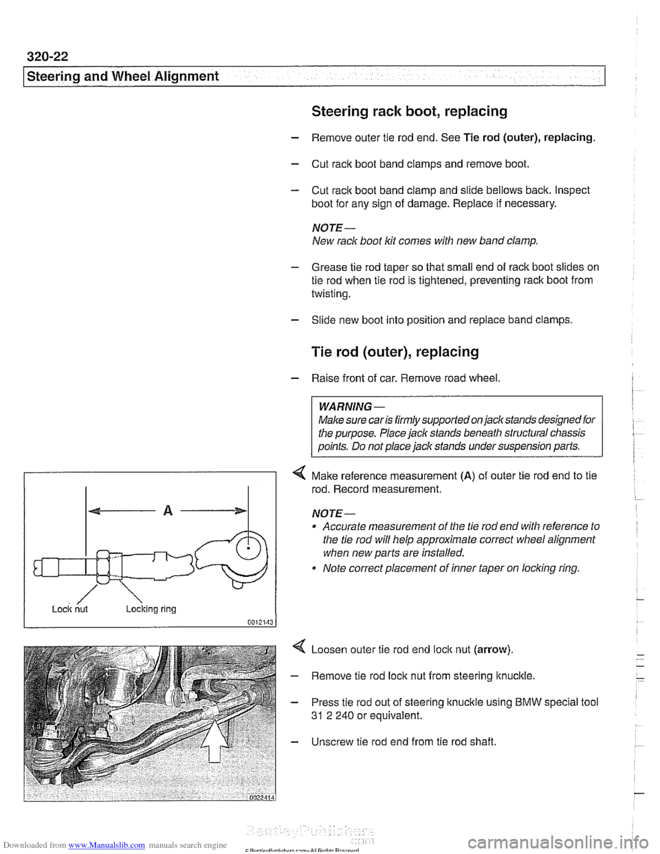
4 Make reference measurement (A) of outer tie rod end to tie
rod. Record measurement.
NOTE-
Accurate measurement of the tie rod end with reference to
the tie rod will help approximate correct
wheel alignment
when new parts are installed.
Note correct placement of inner taper on
loclcing ring.
Loosen outer tie rod end
loclc nut (arrow).
Remove tie rod lock nut from steering
ltnuclcle.
Press tie rod out of steering knuckle using BMW
31 2 240 or equivalent. special tool
Unscrew tie rod end from tie rod shaft.