warning light BMW 540i 1999 E39 Owner's Manual
[x] Cancel search | Manufacturer: BMW, Model Year: 1999, Model line: 540i, Model: BMW 540i 1999 E39Pages: 1002
Page 378 of 1002
Downloaded from www.Manualslib.com manuals search engine
Battery, Starter, Alternator
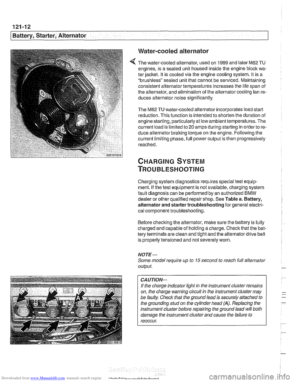
Water-cooled alternator
The water-cooled alternator, used on 1999 and later M62 TU
engines, is a sealed unit housed inside the engine block wa-
ter jacket. It is cooled via the engine cooling system. It is a
"brushless" sealed unit that cannot be serviced. Maintaining
consistent alternator temperatures increases the life span of
the alternator, and elimination of the alternator cooling fan re-
duces alternator noise
significantly.
The M62 TU water-cooled alternator incorporates load start
reduction. This function is intended to shorten the duration of
engine starting, particularly at low ambienttemperatures. The
current load is limited to
20 amps during starting in order to re-
duce alternator braking torque on the engine. Following the
current limiting phase, full power output is then progressively
reached.
Charging system diagnostics requires special test equip-
ment. If the test equipment is not available, charging system
fault diagnosis can be performed by an authorized
BMW
dealer or other qualified repair shop. See Table a. Battery,
alternator and starter troubleshooting for general electri-
cal component troubleshooting.
Before checking the alternator, make sure the battery is fully
charged and capable of holding a charge. Check that the bat-
tery terminals are clean and tight and the alternator drive belt
is properly tensioned and not severely worn.
NOTE-
Some model require up to 15 second to reacli full alternator
output.
CA UTIOG
If the charge indicator light in the instrument cluster remains
on, the charge warning circuit in the instrument cluster may
be faulty. Check that the ground lead is securely
affached to
the grounding stud on the cylinder head
(A). Replacing the
instrument cluster before repairing the ground lead will both
damage the instrument cluster and cause the failure to
reoccur.
Page 379 of 1002
Downloaded from www.Manualslib.com manuals search engine
Battery, Starter, ~lternatorl
Charging system quick-check
Use a digital multimeter to measure voltage across the bat-
tery terminals with key off and then again with engine running.
Battery voltage should be about 12.6 volts with key off and be-
tween 13.5 and 14.5 volts with engine running.
NOTE-
The regulated voltage (engine running) should be between
13.2 and 14.5, depending on temperature andoperating con-
ditions.
If the voltage is higher than 14.8, the voltage regula-
tor or
mulitfunction controller is most likely faulty
Check for clean and tight battery cables. Check ground cable
running from negative
(-) battery terminal to chassis and
ground cable running from engine to chassis. Check alterna-
tor drive belt condition and tension.
Charging system, checking
CAUTIOI\C
* Do not disconnect the battery while the engine is running.
Damage to the alternator and/or engine electronic systems
may result.
Only use a digital multimeter when testing charging
system components.
--7
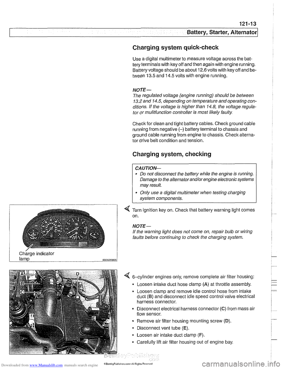
4 Turn ignition key on. Check that battery warning light comes
on.
NOTE-
If the warning light does not come on, repair bulb or wiring
faults before continuing to checlc the charging system.
/ Charge indicator
502820805
4 6-cylinder engines only, remove complete air filter housing:
Loosen
intake duct hose clamp (A) at throttle assembly.
Loosen clamp and remove idle control hose from intake
duct
(B) and disconnect idle speed control valve electrical
harness connector.
Disconnect electrical harness connector
(C) from mass air
flow sensor.
Remove air filter housing mounting screw
(D).
Disconnect vent tube (E).
Loosen air intake duct clamp (F).
Carefully lift air filter housing out of engine bay.
Page 395 of 1002
Downloaded from www.Manualslib.com manuals search engine
Fuel Injection
Warnings and cautions
For personal safety, as well as the protection of sensitive
electronic components, adhere to the warnings and cautions
on the following pages.
WARNING-
Gasoline is highly flammable and its vapors are explosive.
Do not smoke or work on a car near heaters or other fire
hazards when diagnosing and repairing fuel system prob-
lems. Have a fire extinguisher available in case of an emer-
gency
Renew fuel system hoses, clamps and O-rings any
time they are removed.
When working on an open fuel system, wear suitable
hand protection, as prolonged contact
with fuel can
cause illnesses and skin disorders.
* The ignition system produces high voltages that can be
fatal. Avoid contact with exposed terminals. Use ex-
treme caution when
working on a car with the ignition
switched on or the engine running.
CAUTION-
- Disconnecting the battery may erase fault code($ storedin
memory Check for fault codes prior to disconnecting the
battery cables. Read the battery disconnection cautions in
001 General Warnings and Cautions.
a Connect and disconnect the DME system wiring and
1 test equipment leads only when the ignition is switched
off.
Wait at least 1 minute after turning off the ignition be-
fore removing the engine control module (ECM) con-
nector. If the connector is removed before this time,
residualpower in the system relay may damage the
control module.
Fuel system cleaners and other chemical additives oth-
er than those specifically recommended by BMW may
damage the catalytic converter, the oxygen sensor or
other fuel supply components.
* Do not connect any test equipment that delivers a 12-
volt power supply to terminal 15 (+) of the ignition coil.
The current flow may damage the ECM. In general,
connect test equipment only as specified by BMW or
the equipment maker.
Only use a digital
multirneter for electrical tests. Only
use an LED test light for
quiclc tests.
Page 406 of 1002
Downloaded from www.Manualslib.com manuals search engine
I Fuel Injection
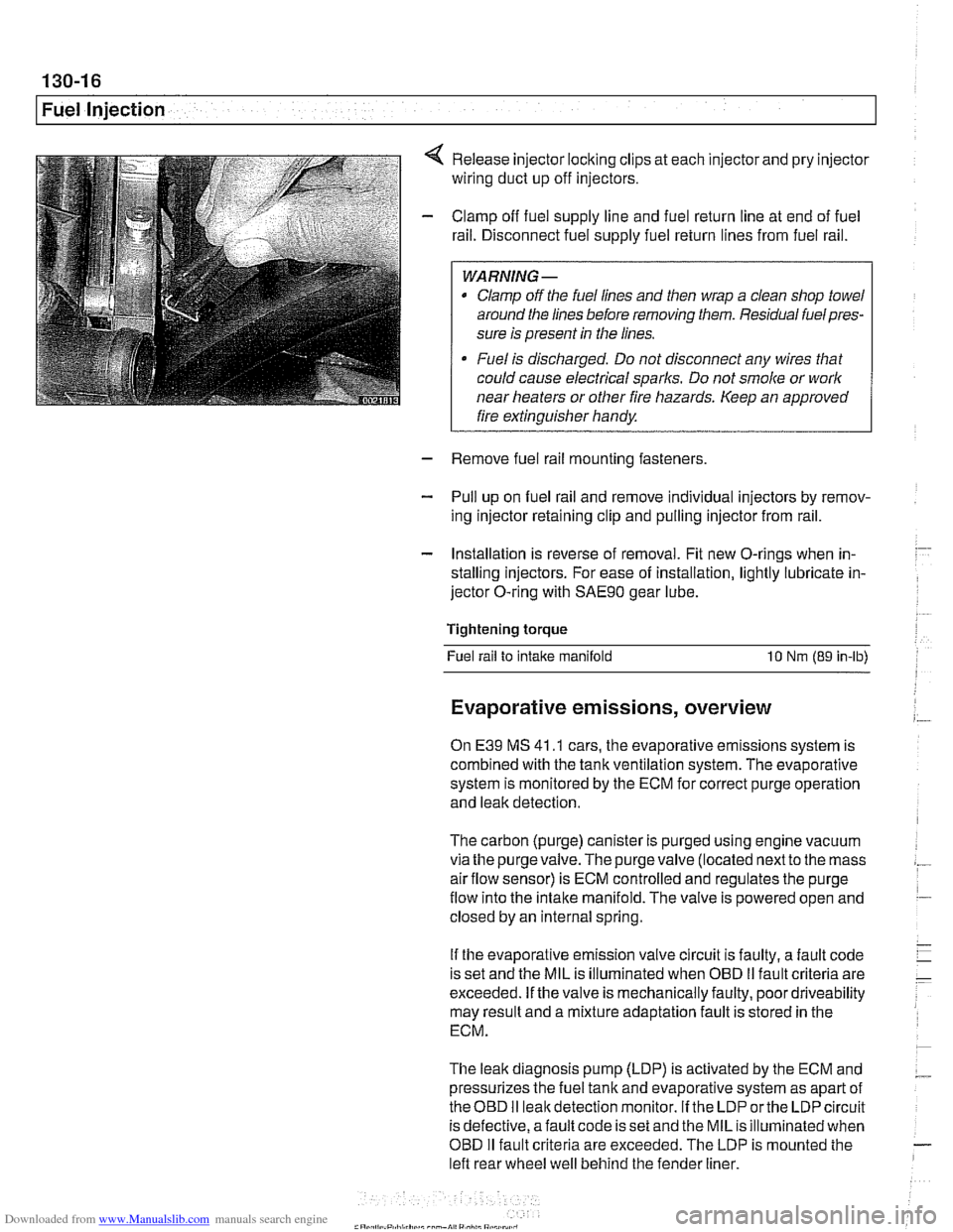
Release injector locking clips at each injector and pry injector
wiring duct up off injectors.
Clamp off fuel supply line and fuel return line at end of fuel
rail. Disconnect fuel supply fuel return lines from fuel rail.
WARNING -
Clamp off the fuel lines and then wrap a clean shop towel
around the lines before removing them. Residual
fuelpres-
sure is present in the lines.
Fuel is discharged. Do not disconnect any wires that
could cause electrical
sparks. Do not smoke or work
near heaters or other fire hazards. Keep an approved
I fire extinguisher handy. I
- Remove fuel rail mounting fasteners
- Pull up on fuel rail and remove individual injectors by remov-
ing injector retaining clip and pulling injector from rail.
- Installation is reverse of removal. Fit new O-rings when in-
stalling injectors. For ease of installation, lightly lubricate in-
jector O-ring with
SAE9O gear lube.
Tightening torque Fuel rail to
intake manifold 10 Nm (89 in-lb)
Evaporative emissions, overview
On E39 MS 41 .I cars, the evaporative emissions system is
combined with the tank ventilation system. The evaporative
system is monitored by the ECM for correct purge operation
and leak detection.
The carbon (purge) canister is purged using engine vacuum
via the
purgevalve.The purgevalve (located nextto the mass
airflow sensor) is ECM controlled and regulates the purge
flow into the intake manifold. The valve is powered open and
closed by an internal spring.
If the evaporative emission valve circuit is faulty, a fault code
is set and the MIL is illuminated when OBD
II fault criteria are
exceeded. If the valve is mechanically faulty, poor driveability
may result and a mixture adaptation fault is stored in the
ECM.
The leak diagnosis pump (LDP) is activated by the ECM and
pressurizes the fuel tank and evaporative system as apart of
theOED I1 leakdetection monitor. If the LDP orthe LDP circuit
is defective, afault code is set and the MIL is illuminated when
OBD
I1 fault criteria are exceeded. The LDP is mounted the
left rear wheel well behind the fender liner.
Page 475 of 1002
Downloaded from www.Manualslib.com manuals search engine
Fuel Tank and Fuel Pump
Warnings and cautions
Observe the following warnings and cautions when servicing
the fuel system.
WARNING-
* The fuel system is designed to retain pressure even when
the ignition is off. When working with the fuelsystem, loos-
en the fuel lines slowly to allow residual
fuel pressure to
dissipate. Avoid spraying fuel. Use shop rags to capture
leaking fuel.
Before beginning any work on the fuel system, place a
fire extinguisher in the vicinity of the work area.
Fuel is highly flammable. When working around fuel, do
not disconnect any wires that could cause electrical
sparks. Do not smoke or worknearheaters or other fire
hazards.
* Always unscrew the fuel tank cap to release pressure
in the
tanlc before working on the tank or lines.
When disconnecting a fuel hose, wrap shop rag around
end of hose to prevent spray of fuel under pressure.
Do not use a work light with an incandescent bulb near
any fuel. Fuel may spray on the hot bulb causing a fire.
0 Make sure the worlc area is properly ventilated.
CAUTION-
- Prior to disconnecting the battery, read the battery discon-
nection cautions given in
001 General Cautions an4
Warnings.
Before
making any electrical tests with the ignition
turned on, disable the ignition system as described in
120 Ignition System. Be sure the battery is discon-
nected when replacing components.
To prevent damage to the ignition system or other DME
components, including the engine control module
(ECM), always connect and disconnect wires and test
equipment with the ignition off.
Cleanliness is essential when
worl~ing with the fuel sys-
tem. Thoroughly clean the fuel line unions before dis-
connecting any of the lines.
Use only clean tools. Keep removed parts clean and
sealed or covered with a clean, lint-free cloth, especial-
ly if completion of the repair is delayed.
Do not move the car while the fuel system is open.
Avoid using high pressure compressed air to blow out
lines and components. High pressure can rupture inter-
nal seals and gaskets.
Always replace seals, O-rings and hose clamps.
Page 525 of 1002
Downloaded from www.Manualslib.com manuals search engine
... .
Exhaust System
- With exhaust system fully cold, raise and support car for ac-
cess to exhaust system.
WARNING -
Do not worlc under a lifted car unless it is solidly supported on
jack stands designed for that purpose. Never work under a
car that is supported solely by a
jack.
- Disconnect oxygen sensor connector(s).
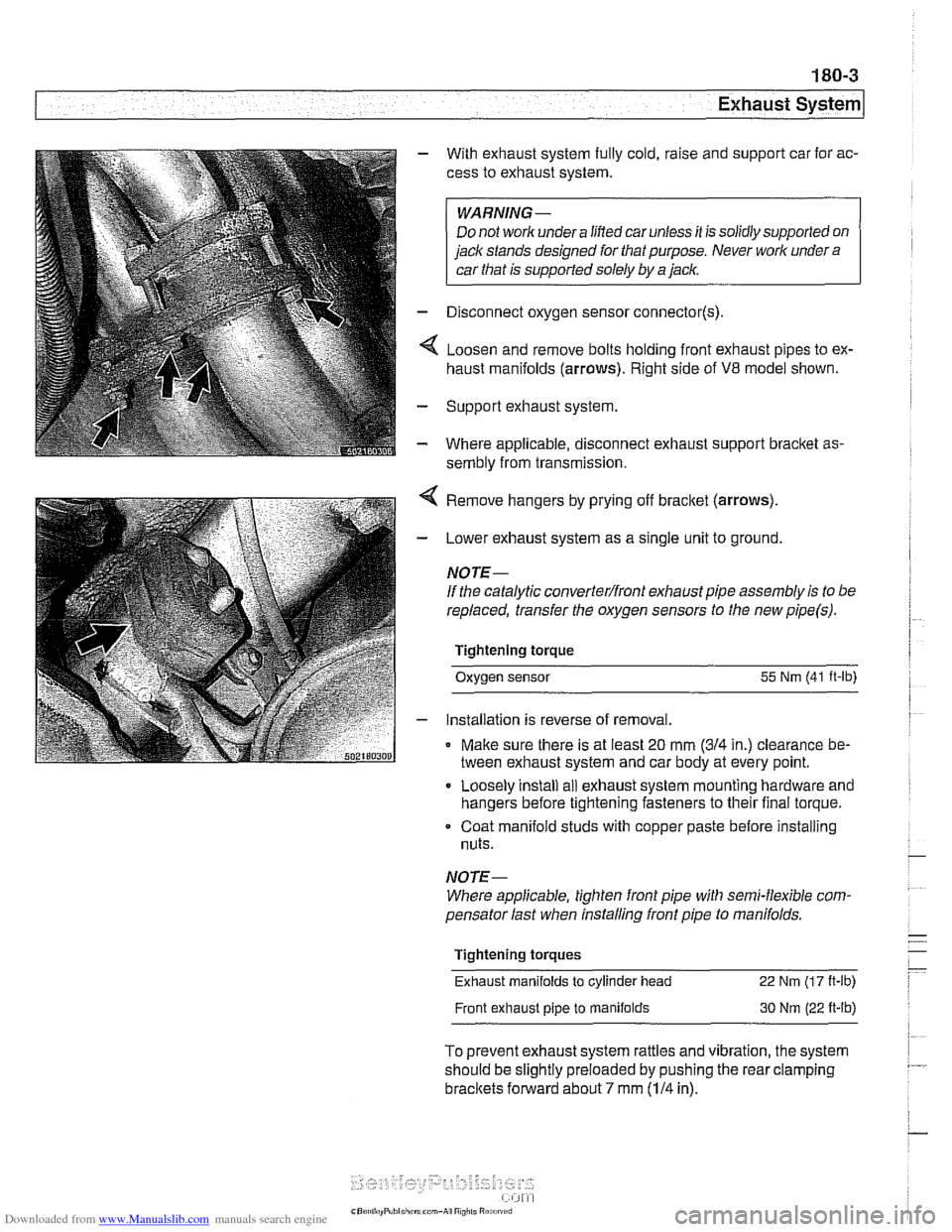
4 Loosen and remove bolts holding front exhaust pipes to ex-
haust manifolds (arrows). Right side of
V8 model shown.
- Support exhaust system
- Where applicable, disconnect exhaust support bracket as-
sembly from transmission.
< Remove hangers by prying off bracket (arrows).
- Lower exhaust system as a single unit to ground.
NOTE-
If the catalytic converterlfront exhaust pipe assembly is to be
replaced, transfer the oxygen sensors to the new
pipe(s).
Tightening torque
Oxygen sensor
55 Nm (41 ft-lb)
- installation is reverse of removal.
* Make sure there is at least 20 mm (314 in.) clearance be-
tween exhaust system and car body at every point.
Loosely install
ail exhaust system mounting hardware and
hangers before tightening fasteners to their final torque.
Coat manifold studs with copper paste before installing
nuts.
NOTE-
Where applicable, tighten front pipe with semi-flexible com-
pensator last when installing front pipe to
manifolds.
Tightening torques
Exhaust manifolds
to cylinder head 22 Nm (1 7 It-lb)
Front exhaust pipe to manifolds 30 Nm (22 ft-lb)
To prevent exhaust system rattles and vibration, the system
should be slightly preloaded by pushing the rear clamping
brackets forward about 7 mm (114 in).
Page 551 of 1002
Downloaded from www.Manualslib.com manuals search engine
- Raise and safely support vehicle
WARNING-
Make sure the car is stable and well supporied at all times.
Use a professional automotive /iff orjack stands designed for
the
ournose. A floor jack is not adeouate suooort.
- If necessary, remove transmission splash shield.
- Disconnect fluid line from slave cylinder on lefl side of trans-
mission. Place pan under hose to catch dripping fluid.
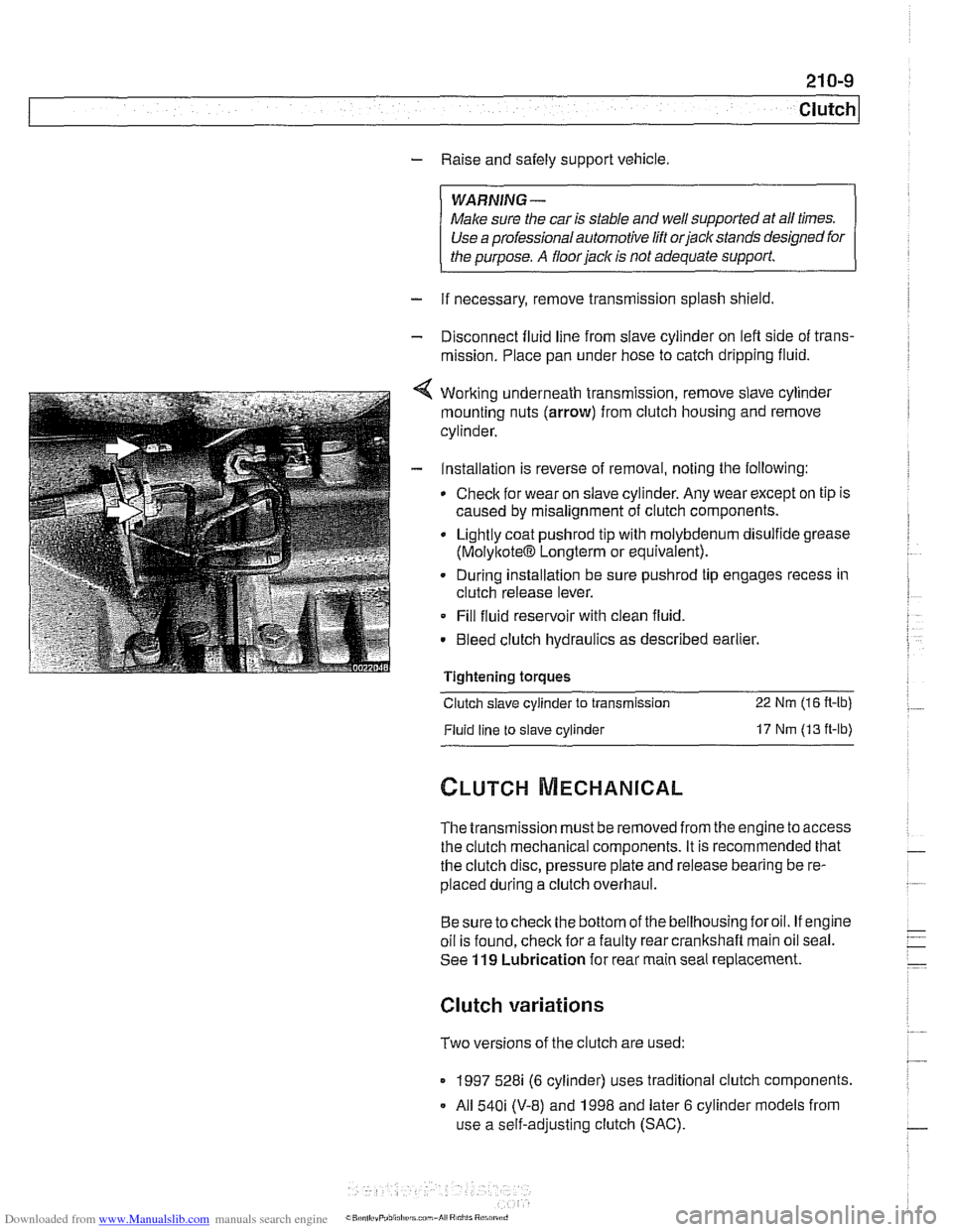
4 Working underneath transmission, remove slave cylinder
mounting nuts (arrow) from clutch housing and remove
cylinder.
- Installation is reverse of removal, noting the following:
Check for wear on slave cylinder. Any wear except on tip is
caused by misalignment of clutch components.
Lightly coat
pushrod tip with molybdenum disulfide grease
(MolyltoteIB Longterm or equivalent).
. During installation be sure pushrod tip engages recess in
clutch release lever.
Fill fluid reservoir with clean fluid.
. Bleed clutch hydraulics as described earlier.
Tightening
toraues - -.
Clutch slave cylinder to transmission 22 Nm (16 R-lb)
Fluid line to slave cylinder 17 Nm (13 ft-lb)
The transmission must be removed from the engine to access
the clutch mechanical components. It is recommended that
the clutch disc, pressure plate and release bearing be re-
placed during a clutch overhaul.
Besure tocheck the bottom of the bellhousing foroil. If engine
oil is found, check for a faulty rear crankshaft main oil seal.
See
119 Lubrication for rear main seal replacement.
Clutch variations
Two versions of the clutch are used:
1997 528i (6 cylinder) uses traditional clutch components.
All
540i (V-8) and 1998 and later 6 cylinder models from
use a self-adjusting clutch (SAC).
Page 571 of 1002
Downloaded from www.Manualslib.com manuals search engine
230-7
Manual Transmission
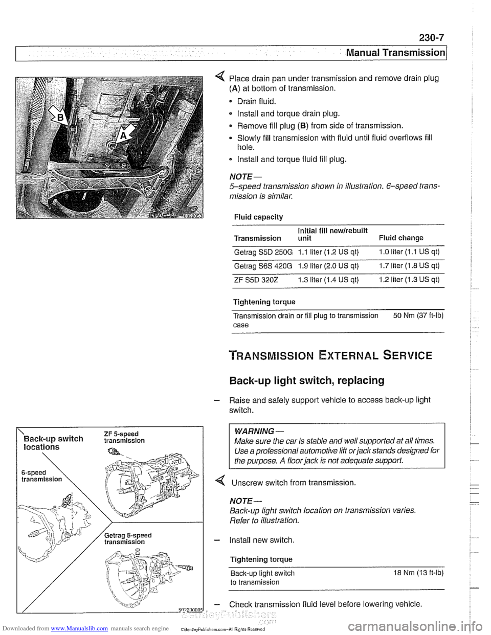
Place drain pan under transmission and remove drain plug
(A) at bottom of transmission.
Drain fluid.
lnstall and torque drain plug.
Remove fill plug
(6) from side of transmission.
Slowly fill transmission with fluid until fluid overflows fill
hole.
lnstall and torque fluid fill
plug.
NOJE-
5-speed transmission shown in illustration. 6-speed trans-
mission is similar.
Fluid capacity
Initial fill
newirebuilt Transmission unit Fluid change
Getrag S5D 250G 1.1 liter (1.2 US qt) 1.0 liter (1 .l US qt)
Getrag S6S 420G 1.9 liter (2.0 US qt) 1.7 liter (1.8 US qt)
ZF S5D 3202 1.3 liter (1.4 US at) 1.2 liter (1.3 US qt)
Tightening torque
Transmission drain or
fill plug to transmission 50
Nm (37 ft-lb)
case
Back-up light switch, replacing
- Raise and safely support vehicle to access back-up light
switch.
WARNING -
4 Unscrew switch from transmission.
Back-up light switch location on transmission varies.
Refer to illustration.
- Install new switch.
Tightening torque Back-up light switch
18 Nm (13 ft-lb)
to transmission
ission fluid level before lowering vehicle.
Page 641 of 1002
Downloaded from www.Manualslib.com manuals search engine
31 0-5
Front ~uspensionl
Front strut assembly, removing and
installing
- Raise car and remove front wheel.
WARNING-
Make sure that the car is firmly supported on jack stands de-
signed for the purpose. Place jack stands underneath struc-
tural chassis points.
Do not place jack stands under
suspension
parts.
- Unbolt bralte caliper assembly, lkeeping bralte hose connect-
ed. Secure brake caliper to body with wire. Do not let it hang
from brake hose. See
340 Brakes.
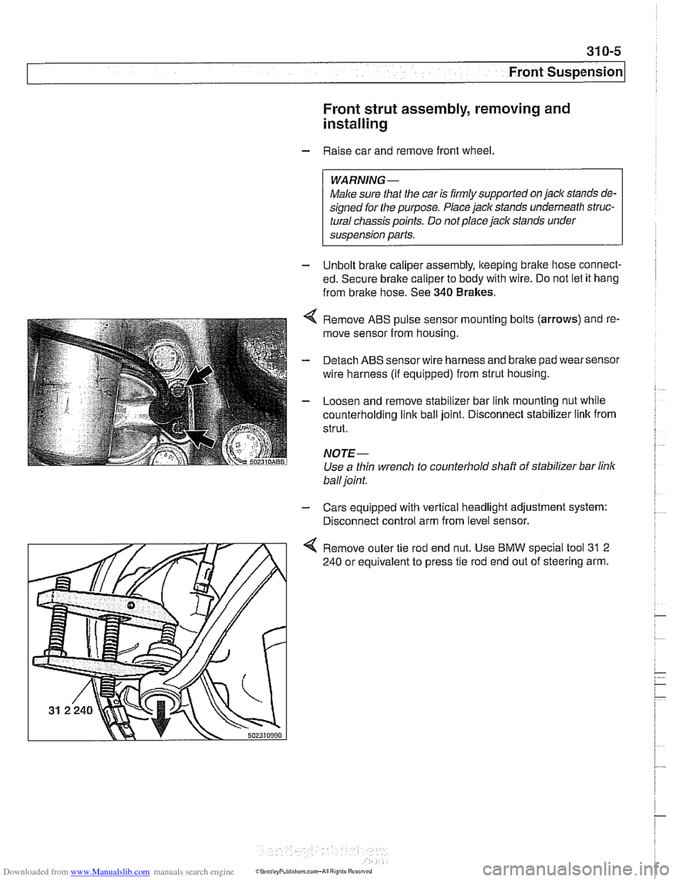
Remove ABS pulse sensor mounting bolts (arrows) and re-
move sensor from housing.
Detach ABS sensor wire harness and bralte pad wear sensor
wire harness (if equipped) from strut housing.
Loosen and remove stabilizer bar link mounting nut while
counterholding
link ball joint. Disconnect stabilizer link from
strut.
NOTE-
Use a thin wrench to counterhold shaft of stabilizer bar link
ball joint.
- Cars equipped with vertical headlight adjustment system:
Disconnect control arm from level sensor.
4 Remove outer tie rod end nut. Use BMW special tool 31 2
240 or equivalent to press tie rod end out of steering arm.
Page 649 of 1002
Downloaded from www.Manualslib.com manuals search engine
Front Suspension
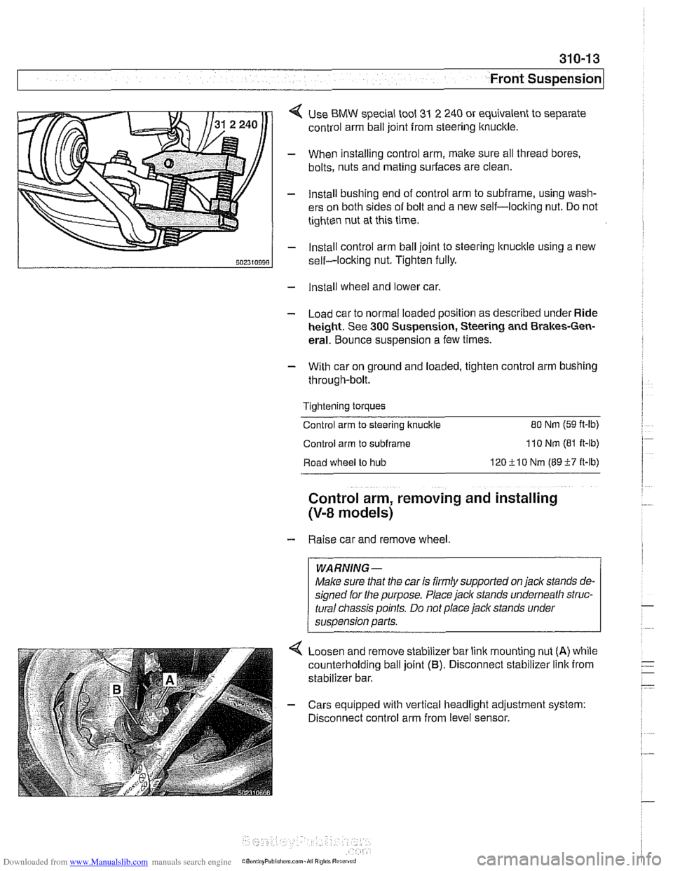
< Use BMW special tool 31 2 240 or equivalent to separate
control arm ball joint from steering ltnuckle.
- When installing control arm, make sure all thread bores.
bolts, nuts and mating surfaces are clean.
- Install bushing end of control arm to subframe, using wash-
ers on both sides of bolt and a new self-locking nut. Do not
tighten nut at this time.
- Install control arm ball joint to steering lknucltle using a new
self-locking nut. Tighten fully.
- Install wheel and lower car.
- Load car to normal loaded position as described under Ride
height. See
300 Suspension, Steering and Brakes-Gen-
eral. Bounce suspension a few times.
- With car on ground and loaded, tighten control arm bushing
through-bolt.
Tightening torques
Control arm to steering ltnuckle
80 Nm (59 ft-lb)
Control arm to subframe 110 Nm (81 It-lb)
Road wheel to hub 120ilO Nm (8957 it-lb)
Control arm, removing and installing
(V-8 models)
- Raise car and remove wheel
WARNING-
Make sure that the car is firmly supported on jack stands de-
signed for the purpose. Place jack stands underneath struc-
tural
cliassis points. Do not place jack stands under
suspension parts.
Loosen and remove stabilizer bar link mounting nut
(A) while
counterholding ball joint
(B). Disconnect stabilizer link from
stabilizer bar.
- Cars equipped with vertical headlight adjustment system:
Disconnect control arm from level sensor.