Head gasket BMW 540i 1999 E39 Service Manual
[x] Cancel search | Manufacturer: BMW, Model Year: 1999, Model line: 540i, Model: BMW 540i 1999 E39Pages: 1002
Page 313 of 1002
Downloaded from www.Manualslib.com manuals search engine
Camshaft Timing Chain
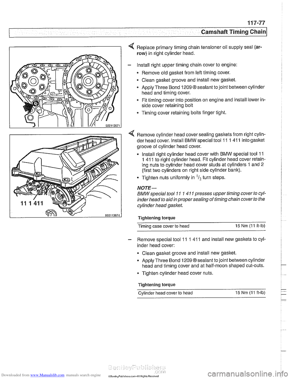
4 Replace primary timing chain tensioner oil supply seal (ar-
row) in right cylinder head.
- Install right upper timing chain cover to engine:
Remove old gasket from
left timing cover.
Clean gasket groove and install new gasket.
Apply Three Bond
1209Osealant to joint between cylinder
head and timing cover.
Fit timing cover into position on engine and install lower in-
side cover retaining bolt
Timing cover retaining bolts finger tight.
4 Remove cylinder head cover sealing gaskets from right cylin-
der head cover. Install
BMW special tool 11 1 41 1 into gasltet
groove of cylinder head cover.
Install right cylinder head cover with
BMW special tool 11
1 41 1 to right cylinder head. Fit cylinder head cover retain-
ing nuts to cylinder head cover studs at cylinders 1 and 2
(first two cylinders on right side cylinder bank).
Tighten nuts uniformly in
'Il turn steps.
NOTE-
BMW special tool 11 1 4 11 presses upper timing cover to cyl-
inder head to aid
in proper sealing of timing chain cover to the
cylinder head gasket.
Tightenlng torque
Timing case cover to head 15
Nm (1 1
It-lb)
- Remove special tool 11 1 41 1 and install new gaskets to cyl-
inder head cover:
Clean gasltet groove and install new gasltet.
Apply Three Bond 1209 Osealant to joint between cylinder
head and timing cover and at half-moon shaped cut-outs.
Tighten cylinder head cover nuts.
Tightenlng torque
-
Cylinder head cover to head 15 Nm (1 1 ft-lb)
Page 314 of 1002
Downloaded from www.Manualslib.com manuals search engine
[camshaft Timina Chain
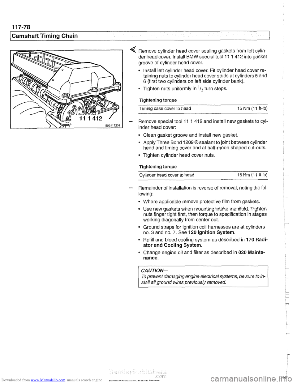
< Remove cylinder head cover sealing gaskets from lefl cylin-
der head cover. Install
BMW special tool 11 1 412 into gasket
groove of cylinder head cover.
Install lefl cylinder head cover. Fit cylinder head cover re-
taining nuts to cylinder head cover studs at cylinders
5 and
6 (first two cylinders on left side cylinder bank).
Tighten nuts uniformly in
'I2 turn steps
Tightening torque
Timing case cover to head
15 Nm (1 1 ft-lb)
- Remove special tool 11 1 41 2 and install new gaskets to cyl-
inder head cover:
Clean gasket groove and install new gasket.
Apply Three Bond
12098sealant tojoint between cylinder
head and timing cover and at half-moon shaped cut-outs.
Tighten cylinder head cover nuts.
Tightening torque Cylinder head cover to head
I5 Nm (1 1 ft-lb)
- Remainder of installation is reverse of removal, noting the fol-
lowing:
Where applicable remove protective film from gaskets.
Use new gaskets when mounting intake manifold. Tighten
nuts finger tight first, then torque to specification in stages
worlting diagonally from center out.
Ground straps for ignition coil harnesses are at cylinders
no.
3 and no. 7. See 120 Ignition System.
Refill and bleed cooling system as described in
170 Radi-
ator and Cooling System.
Change engine oil and filter as described in
020 Mainte-
nance.
CAUTIOI\C
To prevent damaging engine electrical systems, be sure to in-
stall ail ground wires previously removed.
Page 319 of 1002
Downloaded from www.Manualslib.com manuals search engine
Camshaft Timing chain/
- Tighten accessible sprocket retaining bolts in the following
order:
Leit exhaust camshaft
Right exhaust
camshait
Leit intake camshaft
Right
intalte camshait
Tightening torque
Sprocket bolts to camshaft flange
15 Nm (1 1 ft-lb)
- Remove BMW special tool 11 2 300 from tool bore at bell-
housing and remove
camshaft loclting tools from cylinder
heads.
Using crankshaft center bolt, turn engine over clockwise at
least one
comolete rotation so that remainino camshaft
sprocltet
retaking bolts are accessible. -
- Tighten remaining camshait sprocket retaining bolts
Tightening torque Sprocket bolts to camshaft
flange 15 Nm (I 1 It-lb)
- Remove BMW special tool 11 3 390 from primary timing
chain tensioner bore and reinstall primary chain tensioner
- Remainder of installation is reverse or removal, noting the fol-
lowing:
Remove gasket residue from cylinder head sealing sur-
face.
Apply a thin bead of Three Bond 1209
O sealing com-
pound to joints at cylinder head cover and timing case cov-
er and at half-moon sections at rear of cylinder heads.
Replace cylinder head cover
gaskets if necessary.
Page 505 of 1002
Downloaded from www.Manualslib.com manuals search engine
Radiator and Cooling System
Check for cloggedlplugged radiator or coolant passages.
Cooling system pressure test
A cooling system pressure tester is used to test for coolant
leaks, including internal ones. Common sources of internal
coolant leaks are a faulty cylinder head gasket, a
craclted cyl-
inder head, or a cracked engine block.
WARNING-
At normal operating temperature the cooling system is pres-
surized. Allow the system to cool before opening. Release
the cap slowly to allow safe release ofpressure.
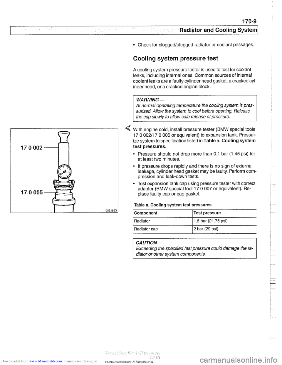
4 With engine cold, install pressure tester (BMW special tools
17 0 002117 0 005 or equivalent) to expansion tank. Pressur-
ize system to specification listed in Table a. Cooling system
test pressures.
Pressure should not drop more than 0.1 bar (1.45 psi) for
at least two minutes.
. If pressure drops rapidly and there is no sign of external
leakage, cylinder head gasket may be faulty. Perform com-
pression and leak-down tests.
Test expansion
tank cap using pressure tester with correct
adapter (BMW special tool 17
0 007 or equivalent). Re-
place faulty cap or cap gasket.
Table a. Cooling system test pressures
0021663 I Component l~est pressure
Radiator
11.5 bar (21.75 psi)
Radiator cap
12 bar (29 psi)
CAUTION-
Exceeding the specified test pressure could damage the ra-
diator or other svstem
com~onents.
Page 506 of 1002
Downloaded from www.Manualslib.com manuals search engine
170-1 0
I Radiator and Cooling System
Combustion chamber leak test
- If you suspect that combustion chamber pressure is leaking
into the cooling system past the cylinder head gasket, use an
exhaust gas analyzer to test the vapors rising from the cool-
ant at the expansion tank.
CAUTIO&
Use an extension tube above the reservoir neclc to main-
tain distance between the top of the coolant and the gas
analyzer
nozzle. The gas analyzer is easily damaged if it is
allowed to inhale liquid coolant.
* While running engine to checlc for causes of overheat-
ing, observe coolant temperature carefully in order to
avoid engine damage.
Thermostat
If the engine overheats or runs too cool and no other cooling
system tests indicate trouble, the thermostat may be faulty.
In
V-8 models and 6-cvlinder models nroduced afler 911 998
(M52TU or M54 eng'ne), rheelecrricaily heated rhermostal IS
mon tored by [he OBD II diagnostlc software The fault may ic
in the DME software or hardware, or it may lie in the wiring to
the thermostat. See
OED On-Board Diagnostics.
Coolant, draining and filling
(6-cylinder models)
WARNING -
Allow the cooling system to cool before opening or draining
the cooling system.
- Raise front of car and support safely.
WARNING -
Make sure the car is stable and well supported at all times.
Use a professional automotive lift
orjack stands designed for
the purpose. A floor jack is not adequate support.
- Remove splash shield from under engine.
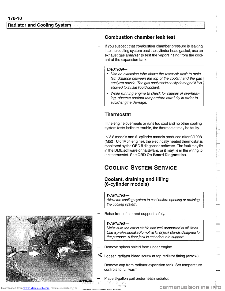
4 Loosen radiator bleed screw at top radiator fitting (arrow).
- Remove cap from radiator expansion tank. Set temperature
controls to
full warm.
gallon pail underneath radiator.
Page 513 of 1002
Downloaded from www.Manualslib.com manuals search engine
Radiator and Cooling systeml
Tightening torques
Block drain plug to block 25 Nm
(18
it-lb)
Coolant hose clamp (32 - 48 2.
5 Nm (22 in-lb)
mm hose diameter)
Radiator drain plug to radiator
2-3Nm(l8-27in-lb)
Thermostat housing to cylinder
head 10 Nm (89 in-lb)
I Coolant thermostat housing assmbly- - I
Thermostat, removing and installing
(M52 TU or M54 engine)
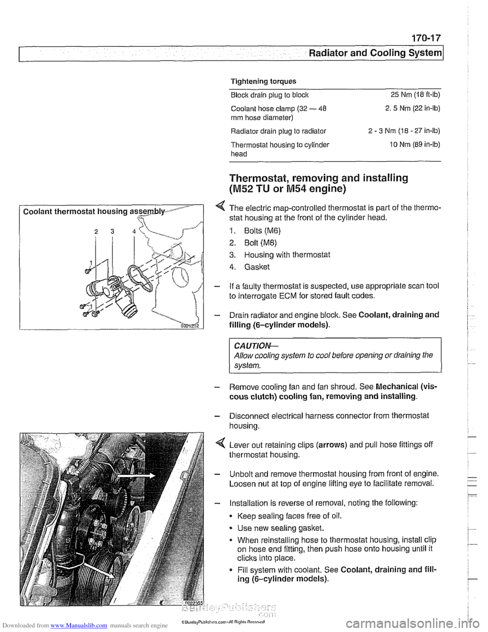
4 The electric map-controlled thermostat is part of the thermo-
stat housing at the front of the cylinder head.
1. Bolts (M6)
2 Bolt (ME)
3. Housing with thermostat
4. Gasket
- If a faulty thermostat is suspected, use appropriate scan tool
to interrogate
ECM for stored fault codes.
- Drain radiator and engine block. See Coolant, draining and
filling (6-cylinder models).
CAUTION-
Allow cooling system to cool before opening or draining the
system.
- Remove cooling fan and fan shroud. See Mechanical (vis-
cous clutch) cooling fan, removing and installing.
- Disconnect electrical harness connector from thermostat
housina.
4 Lever out retaining clips (arrows) and pull hose fittings off
thermostat housing.
- Unbolt and remove thermostat housing from front of engine.
Loosen nut at top of engine lifting eye to facilitate removal.
- Installation is reverse of removal, noting the following:
Keep sealing faces free of oil.
* Use new sealing gasket.
When reinstalling hose to thermostat housing, install clip
on hose end fitting, then push hose onto housing until it
clicks into place.
Fill system with coolant. See Coolant, draining and fill-
ing (6-cylinder models).
Page 527 of 1002
Downloaded from www.Manualslib.com manuals search engine
Exhaust system1
Exhaust manifold removal procedures are organized accord-
ing to engine code. If necessary, see
100 Engine-General
for engine code and application information.
Exhaust manifolds, removing and installing
(M52 engine)
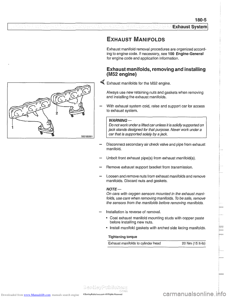
4 Exhaust manifolds for the M52 engine.
Always use new retaining nuts and gaskets when removing
and installing the exhaust manifolds.
- With exhaust system cold, raise and support car for access
to exhaust system.
WARNING -
Do not work under a lined car unless it is solidly supported on
jack stands designed for that purpose. Never work under a
car that is supported solely by a jack.
- Disconnect secondary air check valve and pipe from exhaust
manifold.
- Unbolt front exhaust pipe@) from exhaust rnanifold(s)
- Remove exhaust support bracket from transmission.
- Loosen and remove nuts from exhaust manifolds and remove
manifolds. Discard nuts and gaskets.
NOTE-
On cars with oxygen sensors mounted in the exhaust mani-
folds, use care when removing manifolds.
To be safe, remove
the sensors from the manifolds before removing manifolds.
- Installation is reverse of removal
Coat exhaust manifold mounting studs with copper paste
before installing new nuts.
Install manifold gaskets with arched side facing manifolds.
Tightening torque
Exhaust manifolds
to cylinder head 20 Nm (15 ft-lb)
Page 528 of 1002
Downloaded from www.Manualslib.com manuals search engine
180-6
Exhaust System
Exhaust manifolds, removing and installing
(M52 TU and M54 engines)
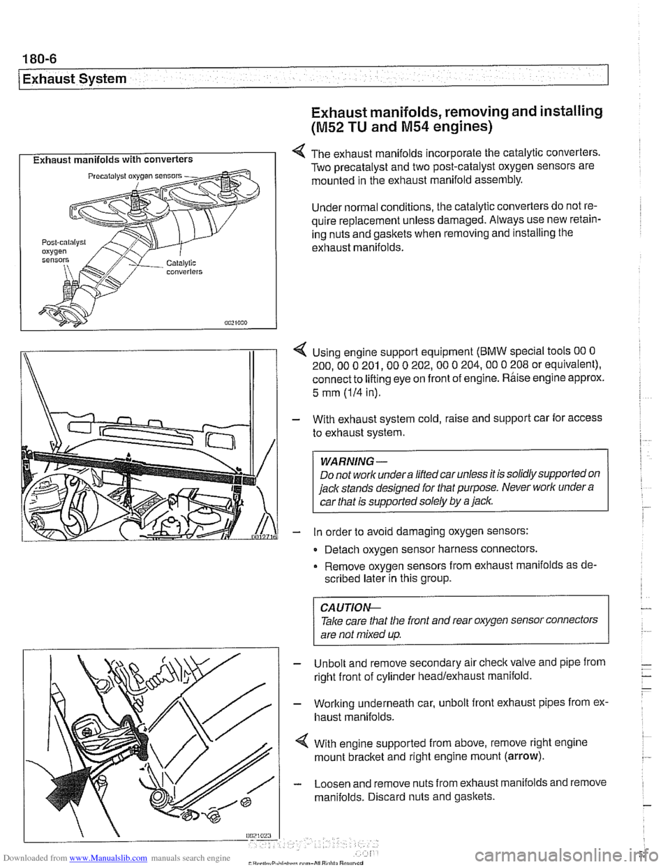
I Exhaust manifolds with converters I 4 The exhaust manifolds incorporate the catalytic converters.
Two precatalyst and two post-catalyst oxygen sensors are
mounted in the exhaust manifold assembly.
Under normal conditions, the catalytic converters do not re-
quire replacement unless damaged. Always use new retain-
ing nuts and gaskets when removing and installing the
exhaust manifolds.
I\
1 4 Using engine support equipment (BMW special tools 00 0
200. 00 0 201. 00 0 202.00 0 204.00 0 208 or equivalent).
connect to
lifting eye on front of engine. Rhise engine approx.
/I 1
5 mm (IH in).
With exhaust system cold, raise and support car for access
to exhaust system.
WARNING-
Do not worlc undera liftedcar unless it is solidly supported on
jack stands designed for that purpose. Never worlc under
a
car that is supported solely by a jaclc.
in order to avoid damaging oxygen sensors:
- Detach oxygen sensor harness connectors,
Remove oxygen sensors from exhaust manifolds as de-
scribed later in this group.
Unbolt and remove secondary air
checkvalve and pipe from
right front of cylinder headlexhaust manifold.
Working underneath car, unbolt front exhaust pipes from ex.
haust manifolds.
With engine supported from above, remove right engine
mount
bracket and right engine mount (arrow).
Loosen and remove nuts from exhaust manifolds and remove
manifolds. Discard nuts and gaskets.
CA UTIOG
Take care tliat the front and rear oxygen sensor connectors
are not mixed up.
-
Page 530 of 1002
Downloaded from www.Manualslib.com manuals search engine
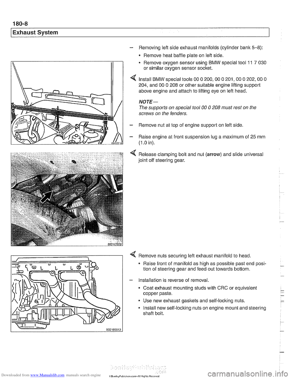
- Removing left side exhaust manifolds (cylinder bank 5-8):
- Remove heat baffle plate on left side.
Remove oxygen sensor using
BMW special tool 11 7 030
or similar oxygen sensor socket.
Install
BMW special tools 00 0 200,OO 0 201,OO 0 202,OO 0
204, and 00 0 208 or other suitable engine lifting support
above engine and attach to lifting eye on left head.
NOTE-
The supports on special tool 00 0 208 must rest on the
screws on the fenders.
- Remove nut at top of engine support on left side
- Raise engine at front suspension lug a maximum of 25 mm
(I
.O in).
Release clamping bolt and nut
(arrow) and slide universal
joint off steering gear.
4 Remove nuts securing left exhaust manifold to head,
Raise front of manifold as high as possible past end posi-
tion of steering gear and feed out towards bottom.
- Installation is reverse of removal.
Coat exhaust mounting studs with CRC or equivalent
copper paste.
Use new exhaust gaskets and self-locking nuts.
Install new self-locking nuts on engine mount and steering
shaft bolt.
Page 533 of 1002
Downloaded from www.Manualslib.com manuals search engine
Exhaust System
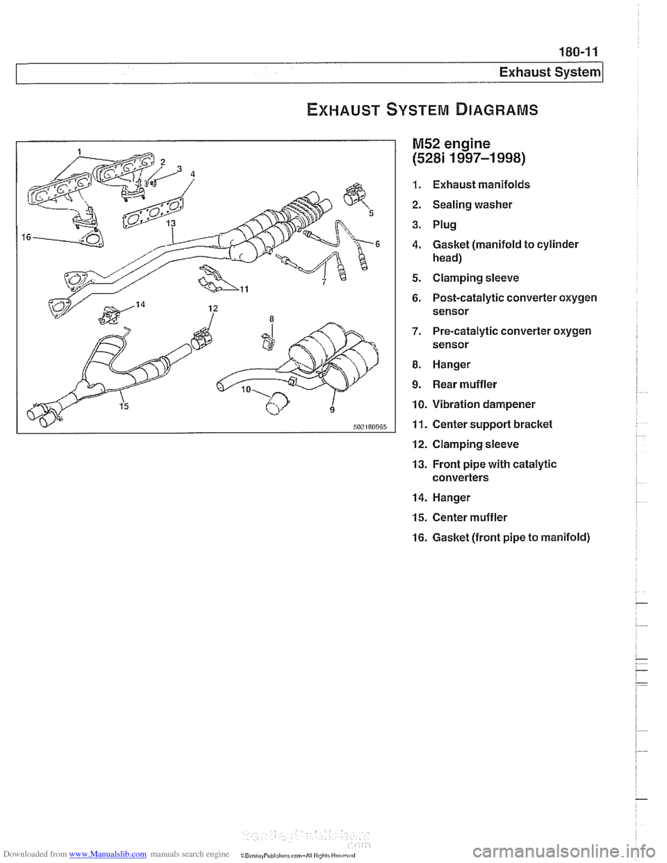
M52 engine
(5281 1997-1 998)
1. Exhaust manifolds
2. Sealing washer
3. Plug
4. Gasket (manifold to cylinder
head)
5. Clamping sleeve
6. Post-catalytic converter oxygen sensor
7. Pre-catalytic converter oxygen
sensor
8. Hanger
9. Rear muffler
10. Vibration dampener
11. Center support bracket
12. Clamping sleeve
13. Front pipe with catalytic
converters
14. Hanger
15. Center muffler
16. Gasket (front pipe to manifold)