relay BMW 540i 1999 E39 Repair Manual
[x] Cancel search | Manufacturer: BMW, Model Year: 1999, Model line: 540i, Model: BMW 540i 1999 E39Pages: 1002
Page 483 of 1002
Downloaded from www.Manualslib.com manuals search engine
Fuel Tank and Fuel Pump
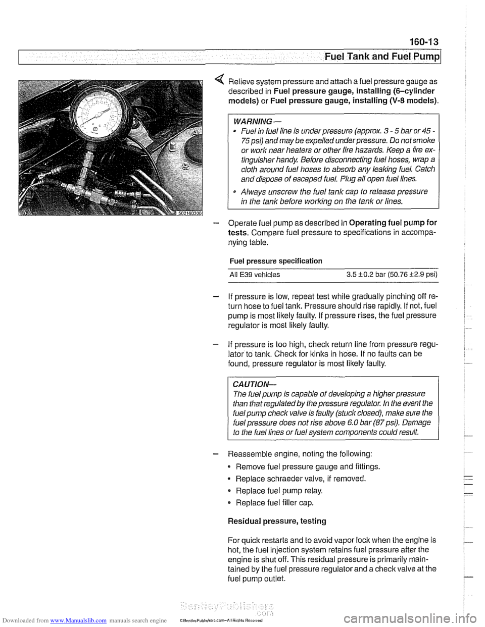
4 Relieve system pressure and attach a fuel pressure gauge as
described in Fuel pressure gauge, installing (6-cylinder
models) or Fuel pressure gauge, installing
(V-8 models).
WARNING-
Fuel in fuel line is under pressure (approx. 3 - 5 bar or 45 -
75psi) and may be expelled underpressure. Do not smoke
or
worlc near heaters or other fire hazards. Keep a fire ex-
tinguisher handy Before disconnecting fuel hoses, wrap a
cloth around fuel hoses to absorb any
leaking fuel. Catch
and dispose of escaped fuel. Plug all open fuel lines.
Always unscrew the fuel tank cap to release pressure
in the tank before
working on the tank or lines.
- Operate fuel pump as described in Operating fuel pump for
tests. Compare fuel pressure to specifications in accompa-
nying table.
Fuel pressure specification
All E39 vehicles 3.5 +0.2 bar (50.76 i2.9 psi)
- If pressure is low, repeat test while gradually pinching off re-
turn hose to fuel tank. Pressure should rise rapidly. If not, fuel
pump is most likely faulty. If pressure rises, the fuel pressure
regulator is most
likely faulty.
- If pressure is too high, checlc return line from pressure regu-
lator to tank. Check for
ltinks in hose. If no faults can be
found, pressure regulator is most likely faulty.
CAUTION-
The fuel pump is capable of developing a higher pressure
than that regulated by the pressure regulator. In the event the
fuel pump checlc valve is faulty (stuck closed), male sure the
I fuel pressure does not rise above 6.0 bar (87psi). Damage
to the fuel lines or fuel system components could result.
- Reassemble engine, noting the following:
Remove fuel pressure gauge and fittings.
Replace schraeder valve, if removed
Replace fuel pump relay.
Replace fuel filler cap.
Residual pressure, testing
For quick restarts and to avoid vapor lock when the engine is
hot, the fuel injection system retains fuel pressure after the
engine is shut off. This residual pressure is primarily
rnain-
tained by the fuel pressure regulator and a checlc valve at the
fuel pump
outlet.
Page 697 of 1002
Downloaded from www.Manualslib.com manuals search engine
330 Rear Suspension
General . . . . . . . . . . . . . . . . . . . . . . . . . . . ,330-2
Special tools . . . . . . . . . . . . . . . . . . . . . . . . ,330-2
Rear suspension variations . . . . . . . . . . . . ,330-4
Rear Struts and Springs
(sedan models)
. . . . . . . . . . . . . . . . . . . . ,330-5
Rear strut assembly, removing
and installing
. . . . . . . . . . . . . . . . . . . . . . . ,330-5
Rear strut assembly, disassembling
and assembling
. . . . . . . . . . . . . . . . . . . . . ,330-7
Rear Shock Absorbers and
Springs (Sport Wagon models)
. . . . . ,330-9
Rear shock absorber, removing
and installing
. . . . . . . . . . . . . . . . . . . . . . . ,330-9
Coil spring, removing and installing . . . . . ,330-1 1
Air spring, removing and installing
. . . . . . ,330-12
Rear Suspension Arms,
Subframe and Bushings . . . . . . . . . . ,330-13
Rear suspension arm components . . . . . . ,330-1 3
Swing arm, removing and installing (sedan models)
. . . . . . . . . . . . . . . . . . . . . ,330-1 4
Swing arm, removing and installing (Sport Wagon models)
. . . . . . . . . . . . . . . ,330-16
Swing arm ball joint, replacing . . . . . . . . . ,330-1 9
Upper rear control arm, removing
and installing (sedan models)
. . . . . . . . . . .330-22
Upper rear control arm, removing
and installing (Sport Wagon models)
. . . . .330-23
Upper front control arm (traction strut),
removing and installing
. . . . . . . . . . . . . . . ,330-25
Rear axle assembly, removing and
installing (sedan models)
. . . . . . . . . . . . . ,330-26
Rear axle assembly, removing and
installing (Sport Wagon models)
. . . . . . . ,330-28
Rear subframe mounting bushings,
removing and installing
. . . . . . . . . . . . . . . .330-31
Rear Wheel Bearings . . . . . . . . . . .
Rear wheel bearing carrier, removing
and installing (sedan models)
. . . . . . .
Rear wheel bearing carrier, removing
and installing (Sport Wagon models)
. .
Rear wheel bearing, replacing . . . . . . .
Rear Stabilizer Bar
Stabilizer bar, removing and installing .
Stabilizer bar link, removing
and installing
. . . . . . . . . . . . . . . . . . . .
Electronic Height Control (EHC)
Component Replacement
. . . . . . .
Electronic height control (EHC)
components
.....................
Air compressor pump relay, removing
and installing
. . . . . . . . . . . . . . . . . . . .
EHC control module, removing
and installing
. . . . . . . . . . . . . . . . . . . .
Air supply unit, removing and installing
Ride height sensor, removing
and installing
. . . . . . . . . . . . . . . . . . . .
Page 740 of 1002
Downloaded from www.Manualslib.com manuals search engine
---
Rear Suspension
ELECTRONIC HEIGHT CONTROL
(EHC) COMPONENT REPLACEMENT
Sport Premium rear suspension is an option on Sport Wagon
models and standard on
1999 and later V-8 Sport Wagons.
This suspension incorporates electronic height control
(EHC)
using air springs.
With vehicle lifted off the ground,
if the rear air springs can be
compressed by hand, either the spring is defective or the sys-
tem is depressurized.
Locate
EHC faults using BMW scan tools DIS or MoDiC. EHC
description and some troubleshooting is covered in 300 Sus-
pension, Steering and Brakes-General.
Air spring replacement is covered earlier in this chapter. See
Air spring, removing and installing.
CAUTION-
Maintain high levels of cleanliness around air line connec-
tions when disassembling and assembling air suspension
components. Even
small dirt particles can cause leakage in
the pressurized system.
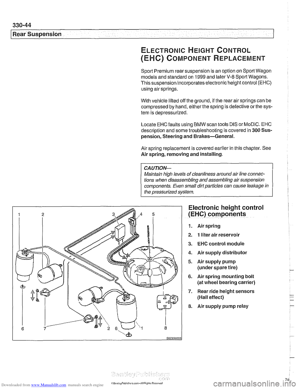
Electronic height control
(EHC) components
1. Air spring
2. 1 liter air reservoir
3. EHC control module
4. Air supply distributor
5. Airsupply pump
(under spare tire)
6. Air spring mounting bolt
(at wheel bearing carrier)
7. Rear ride height sensors
(Hall effect)
8. Air supply pump relay
Page 741 of 1002
Downloaded from www.Manualslib.com manuals search engine
-- I
I: ... . -. Rear Suspension! -- .- -
Air compressor pump relay, removing and
installing
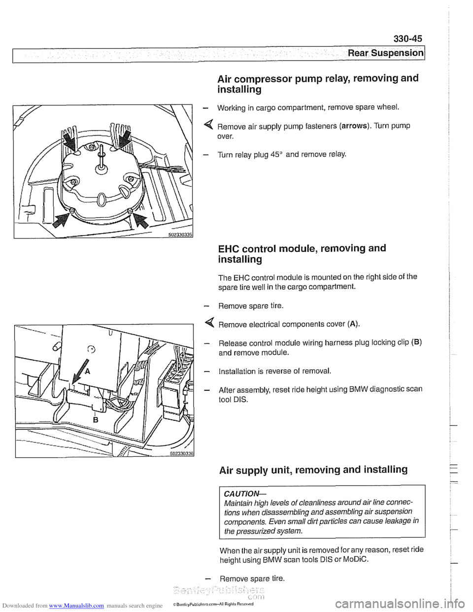
- Working in cargo compartment, remove spare wheel.
4 Remove air supply pump fasteners (arrows). Turn pump
over.
- Turn relay plug 45" and remove relay.
EHC control module, removing and
installing
The EHC control module is mounted on the right side of the
spare tire
well in the cargo compartment.
- Remove spare tire.
4 Remove electrical components cover (A).
- Release control module wiring harness plug loclting clip (B)
and remove module.
- Installation is reverse of removal.
- After assembly, reset ride height using BMW diagnostic scan
tool DIS.
Air supply unit, removing and installing
CAUTION-
Maintain high levels of cleanliness around air line connec-
tions when disassembling and assembling air suspension
components. Even small dirt particles can cause
leakage in
the pressurized system.
When the airsupply unit is removed for any reason, reset ride
height using BMW scan tools DIS or
MoDiC.
- Remove spare tire.
i~B,!n,,ayPubi.l,c~u.c~"~-A~~ R
Page 799 of 1002
Downloaded from www.Manualslib.com manuals search engine
400-5
Body-General
Tailgate
The E39 Sporl Wagon tailgate is large with a low sill for easy
cargo loading. The tailgate opens to an angle of
88" mea-
sured from the rear roof pillar (D-pillar) and to a height of
2029
mm (79.8 in) measured from the ground to the upper edge of
the raised tailgate.
The rear window is bonded to a load bearing frame and can
be opened separately from the main tailgate. Tailgatesupport
gas springs are recessed into cavities in the roof.
Tailgate lock system
A mechanical tailgate lock cylinder is not used; the tailgate is
opened by the unlock pad above the license plate, the remote
tailgate switch located in the drivers kick panel, or via
FZV
(Iteyless entry) control.
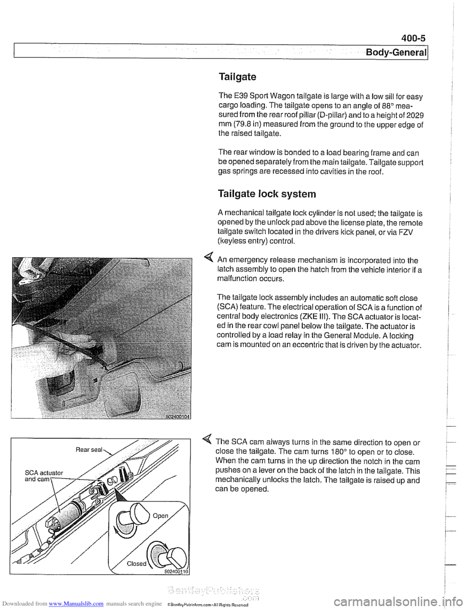
4 An emergency release mechanism is incorporated into the
latch assembly to open the hatch from the vehicle interior if a
malfunction occurs.
The tailgate lock assembly includes an automatic soft close
(SCA) feature. The electrical operation of SCA is a function of
central body electronics
(ZKE Ill). The SCA actuator is locat-
ed in the rear cowl panel below the tailgate. The actuator is
controlled by a load relay in the General Module. A locking
cam is mounted on an eccentric that is driven by the actuator.
4 The SCA cam always turns in the same direction to open or
close the tailgate. The cam turns
180" to open or to close.
When the cam turns in the up direction the notch in the cam
SCA actuator pushes on a lever on the back of the latch in the tailgate. This
mechanically unlocks the latch. The tailgate is raised up and
can be opened.
Page 868 of 1002
Downloaded from www.Manualslib.com manuals search engine
51 2-4
I Door Windows
/ Anti-trap strip
Power window motors
The window motors are mounted on cable regulators. The
window motor control circuit consists of two wires for operat-
ing the motor in both directions.
The motors are activated by relays in the GM
Ill. The relays
provide either power or ground depending on the direction of
window travel. The GM
Ill controls the polarity based on a re-
quest to run the window from a window switch or a conve-
nience
openinglclosing signal.
Convenience openinglclosing
The GM Iii provides the convenience openlclose feature, pro-
viding control of the power windows (and sunroof) from out-
side the vehicle with the key in the driver's door lock. The FZV
(remote key) provides the same function for window opening
only.
Anti-trap protection is active during convenience closing from
the driver's door lock.
If the GM receives a request to operate convenience closing
or opening for more than
110 seconds, the function is deacti-
vated and a
fault code is stored.
Window anti-trap protection
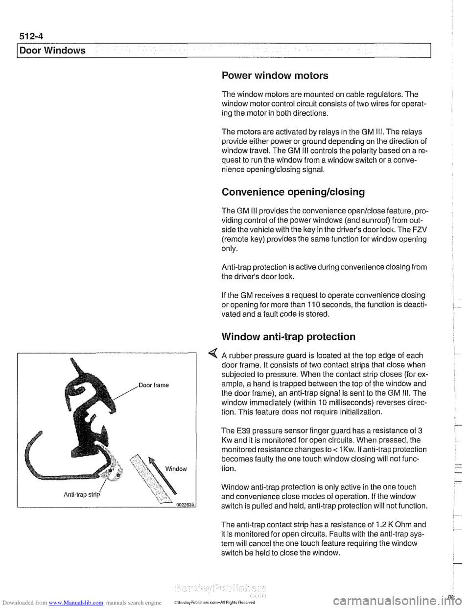
4 A rubber pressure guard is located at the top edge of each
door frame. It consists of two contact strips that close when
subjected to pressure. When the contact strip closes (for ex-
ample, a hand is trapped between the top of the window and
the door frame), an anti-trap signal is sent to the GM
Ill. The
window immediately (within
10 milliseconds) reverses direc-
tion. This feature does not require
initialization.
The E39 pressure sensor finger guard has a resistance of 3
Kw and it is monitored for open circuits. When pressed, the
monitored resistance changes to
< 1 Kw. if anti-trap protection
becomes faulty the one touch window closing will not func-
tion.
Window anti-trap protection is
only active in the one touch
and convenience close modes of operation. If the window
switch is pulled and held, anti-trap protection will not function.
The anti-trap contact strip has a resistance of
1.2 K Ohm and
it is monitored for open circuits. Faults with the anti-trap sys-
tem will cancel the one touch feature requiring the window
switch be held to close the window.
Page 869 of 1002
Downloaded from www.Manualslib.com manuals search engine
Door windows1
Window motor limit stop function
If repeated window activation (upldown cycles) exceeds one
minute, the
GM Ill deactivates the internal relays and disre-
gards any further
upldown requests. The GM Ill provides mo-
tor activation after a short duration but not for the full one
minute monitoring cycle.
The
GM Ill monitors the number of times a window motor is
activated. It counts each cycle and stores the number in
memory. Afler the stop function limit is reached and the win-
dow motor is deactivated, the
GM Ill slowly reverses the
stored count of activation until the stored number equals
0,
thus allowing the window motor to cool down.
WARNING-
* Always wear hand and eye protection when working with
brolen glass.
If a window is brolen, all of the glass bits should be
vacuumed out of the door cavity. Use a blunt
so-ewdi-iv-
er to clean out any remaining glass pieces from the
window guide rails.
When servicing the door windows, the harness con-
nector to the window regulator should always be dis-
connected to prevent pinching fingers in the moving
window mechanism.
Sedan and Sport Wagon doors are similar. Use the following
procedures for window service on these models.
WARNING-
E39 cars are iitted with side-impact airbags in the front
doors. Some are equipped with
airbags in the rear doors
as well. When
servicing the door windows on cars with
side-impact airbags, always disconnect the negative
(-)
battery cable. See 721 Airbag System (SRS) for cau-
tions and procedures relating to the
airbag system.
* Prior to disconnecting the battery, read the battery dis-
connection cautionsgiven
001 General Warnings and
Cautions.
Page 896 of 1002
Downloaded from www.Manualslib.com manuals search engine
51 5-2
/Central Locking and Anti-Theft
This section covers repair information for door, trunk and car-
go compartment locks, central locking, electronic
immob~liza-
tion (EWS) and anti-theft alarm (DWA).
€39 cars are equipped with sophisticated self-diagnostic elec-
trical systems. When experiencing malfunctions relating to
central locking. EWS or anti-theft systems, start the diagnosis
process using the
BMW service tester DIS, GT 1, MoDiC or
equivalent scan tool. An advanced diagnostic scan tool can
usually pinpoint electrical faults quickly and safely.
Additional electrical information can be found in:
610 Electrical Component Locations
ELE Electrical Wiring Diagrams
Central locking in E39 vehicles controls the door
locks, trunk
or tailgate lock and fuel filler flap lock. The control module for
the Central Body Electronics system (ZKE
Ill), lknown as the
General Module (GM
Ill), controls central locking.
ZKE
Ill manages the following central locking related func-
tions:
Central locking
* Keyless entry
Key memory
Power trunk release
Electric opening of tailgate
DWA alarm system
Diagnosis
General Module
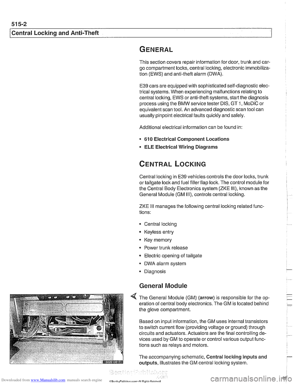
4 The General Module (GM) (arrow) is responsible for the op-
eration of central body electronics. The GM is located behind
the glove compartment.
Based on input information, the GM uses internal transistors
to switch current flow (providing voltage or ground) through
circuits and actuators. Actuators are the final controlling de-
vices used by GM to operate or control various output func-
tions such as relays and motors.
The accompanying schematic, Central locking inputs and
outputs, illustrates the GM central locking system.
Page 907 of 1002
Downloaded from www.Manualslib.com manuals search engine
- -
Central Locking and ~nti-~hefil
Key Memory
Whenever one of the FZV keys is used to lock or unlock the
car, the user is identified by the GM. A maximum of four
keys
can be programmed with the Key Memoryfeature. The use of
the personalized key then triggers Car Memory functions
such as heating
I AIC (IHKA) settings or memory seat position
adjustment.
Most programming of Key Memory requires the use of
BMW
scan tools (DISplus, GT1 or MoDiC). However, features such
as
IHKA blower speed and temperature store automatically
without the use of scan tools.
Available Key Memory functions vary based on vehicle equip-
ment. The functions that can be set include:
Automatic locking after start off (vehicle speed)
Selective locking
Heating
1 AJC blower speed, heated or cooled air distribu-
tion, automatic blower setting
Trunk lid soft close (SCA)
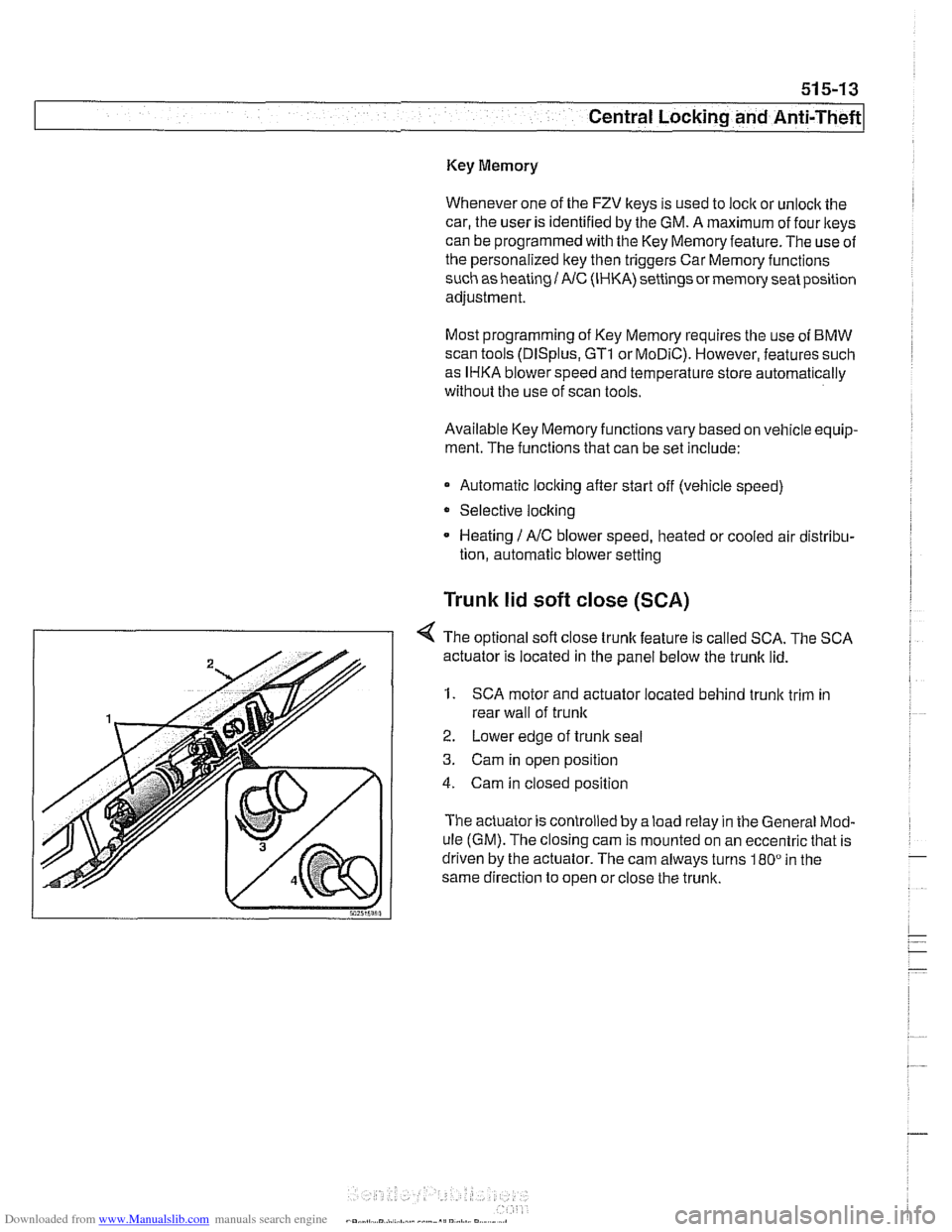
< The optional sofl close trunk feature is called SCA. The SCA
actuator is located in the panel below the trunk lid.
1. SCA motor and actuator located behind trunk trim in
rear wall of
trunlc
2. Lower edge of trunlc seal
3. Cam in open position
4. Cam in closed position
The actuator is controlled by a load relay in the General Mod-
ule (GM). The closing cam is mounted on an eccentric that is
driven by the actuator. The cam always turns
180" in the
same direction to open or close the trunk.
Page 909 of 1002
Downloaded from www.Manualslib.com manuals search engine
51 5-1 5
Central Locking and Anti-Theft
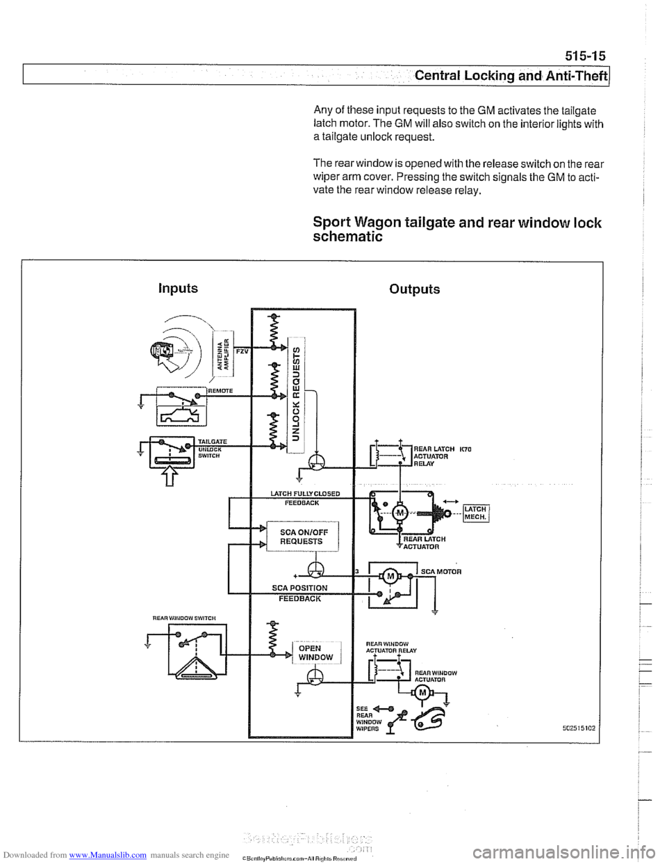
Any of these input requests to the GM activates the tailgate
latch motor. The
GM will also switch on the interior lights with
a tailgate unlock request.
The rearwindow is opened with the release switch on the rear
wiper arm cover. Pressing the switch signals the GM to acti-
vate the rear window release relay.
Sport Wagon tailgate and rear window lock
schematic
Inputs Outputs
"UiRWiNOOW ACTUATOR RELAY
RUiRWINDOW ACTUlimR A L
WIPERS