fuse diagram BMW 540i 1999 E39 Workshop Manual
[x] Cancel search | Manufacturer: BMW, Model Year: 1999, Model line: 540i, Model: BMW 540i 1999 E39Pages: 1002
Page 397 of 1002
Downloaded from www.Manualslib.com manuals search engine
Fuel Injection 1
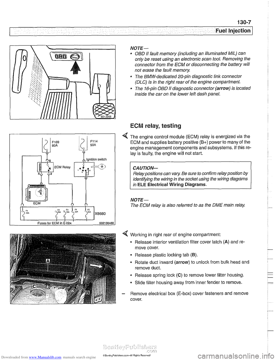
Working in right rear of engine compartment:
Release interior ventilation filter cover latch
(A) and re-
move cover.
Release plastic locking tab
(6).
Rotate duct inward (arrow) to unlock from bulk head and
remove duct.
Release spring
lock (C) to remove lower iilter housing.
Slide filter housing away from inner fender to remove.
- Remove electrical box (E-box) cover fasteners and remove
cover.
NOTE-
OBD I1 fault memory (including an illuminated MIL) can
only be reset using an electronic scan tool. Removing the
connector from the ECM or disconnecting the battery will
not erase the fault
memory.
The BMW-dedicated 20-pin diagnostic linlc connector
(DLC) is in the right rear of the engine compartment.
The 16-pin OBD
I1 diagnostic connector (arrow) is located
inside the car on the lower left dash panel.
ECM relay, testing
Fuses lor ECM In E-bbx 502130488
4 The engine control module (ECM) relay is energized via the
ECM and supplies battery positive
(B+) power to many of the
engine management components and subsystems.
If this re-
lay is faulty, the engine will not start.
Relay positions can vary. Be sure to confirm relay position by
identifying the wiring in the socket using the wiring diagrams
in
ELE Electrical Wiring Diagrams.
NOTE-
The ECM relay is also referred to as the DME main relay.
Page 398 of 1002
Downloaded from www.Manualslib.com manuals search engine
130-8
Fuel Injection
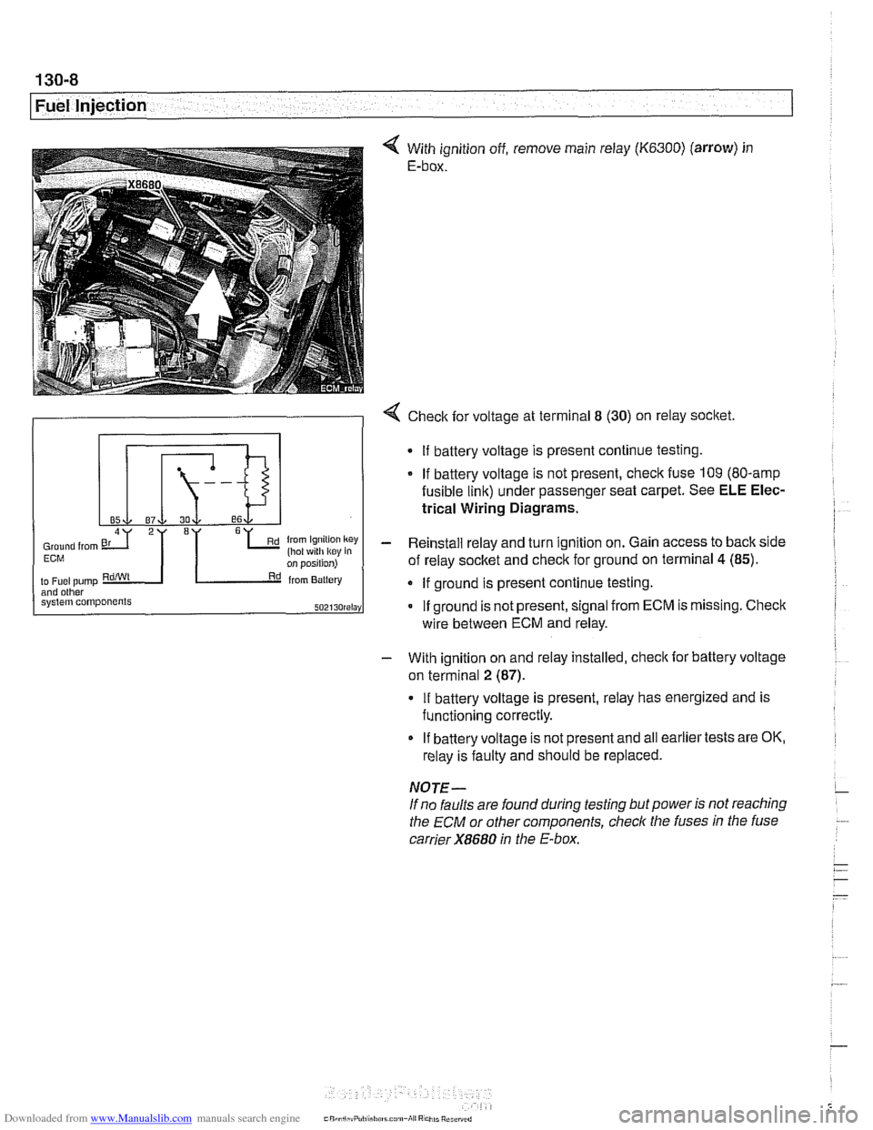
With ignition off, remove main relay (K6300) (arrow) in
E-box.
- With ignition on and relay installed, check for battery voltage
on terminal
2 (87).
4 Check for voltage at terminal 8 (30) on relay socket.
If battery voltage is present, relay has energized and is
functioning correctly.
Gmund from 6L (hot ~4th k~y key in Ern
2I '1
on position)
to
Fuel pump RdiWt Rd from Battery and other system components SOZI~O~~I~Y
If battery voltage is not present and all earlier tests are OK,
relay is faulty and should be replaced.
If
battery voltage is present continue testing.
If battery voltage is not present, check fuse 109 (80-amp
fusible link) under passenger seat carpet. See ELE Elec-
trical Wiring Diagrams.
- Reinstall relay and turn ignition on. Gain access to back side
of relay socket and check for ground on terminal
4 (85).
If ground is present continue testing.
If ground is not present, signal from ECM is missing. Check
NOTE-
If no faults are found during testing but power is not reaching
the
ECM or other components, check the fuses in the fuse
carrier
X8680 in the E-box.
wire
between ECM and relay.
Page 440 of 1002
Downloaded from www.Manualslib.com manuals search engine
130-50
Fuel Injection
Bosch M5.2
ECM relay
1 HoL al ail iirnel XOL a1 ail limes
i--[-----i F109 (BOA) electronics I L.$.....: .I:
ECM relay . . . . . . . . . ,
8,s
:,
6 1 .. ... ~~.~~. . ...... .-, Engine control ii~~-~.~~..~ ........ ~~~~~~.~~~~:. module relay -;I
Of?
,c,;,,,
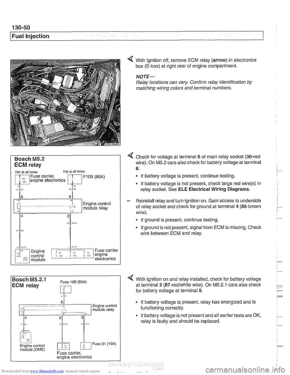
< With ignition off, remove ECM relay (arrow) in electronics
box (E-box) at right rear of engine compartment.
NOTE-
Relay locations can vary. Conh relay identification by
matcliing wiring colors and terminal numbers.
4 Check for voltage at terminal 6 of main relay socket (30-red
wire). On M5.2 cars also check for battery voltage at terminal
8.
. . . . . . . . . ,
If battery voltage is present, continue testing
.
If battery voltage is not present, check large red wire(s) in
relay socltet. See
ELE Electrical Wiring Diagrams.
%P,,tt
- Reinstall relay and turn ignition on. Gain access to underside
of relay socket and
checlc for ground at terminal 4 (85-brown
wire).
. . . . . . . . . . . . - - - - - - - - - . - - - . . l ,,-. ; Engine i f .: , ; Fuse carrier .,A . :engine /;is? /control L.!.!! .... 1.: ...... !.::..! I lij :module electronics If
ground is present, continue testing
If ground is not present, signal from ECM is missing. Checic
wire between ECM and relay.
4 With ignition on and relay installed, check for battery voltage
at terminal
2 (87-redlwhite wire). On M5.2.1 cars also checlc
for battery voltage at terminal 5.
If battery voltage is present, relay has energized and is
functioning correctly.
If battery voltage is not present and all earlier tests are OK,
relay is faulty and should be replaced.
Page 441 of 1002
Downloaded from www.Manualslib.com manuals search engine
130-51
Fuel Injection
Oxygen sensors, checking
The oxygen sensor provides an input voltage signal [0.2 vdc
(lean) to 0.8 vdc (rich)] to the
ECM based on the oxygen con-
tent in the exhaust gas. To generate voltage, the sensor tem-
perature must exceed 575"
F (300" C). Therefore the sensor
is electrically heated.
NO JE -
The test given below is not a conclusive test of oxygen sen-
sor efficiency and does not test how the oxygen sensor re-
acts to changing conditions. Pin numbers and wire colors
can vary Always check the wiring diagrams to confirm wire
color and pin assignment.
0 The oxygen sensorconnectorplugs are locatednext to the
catalytic converters.
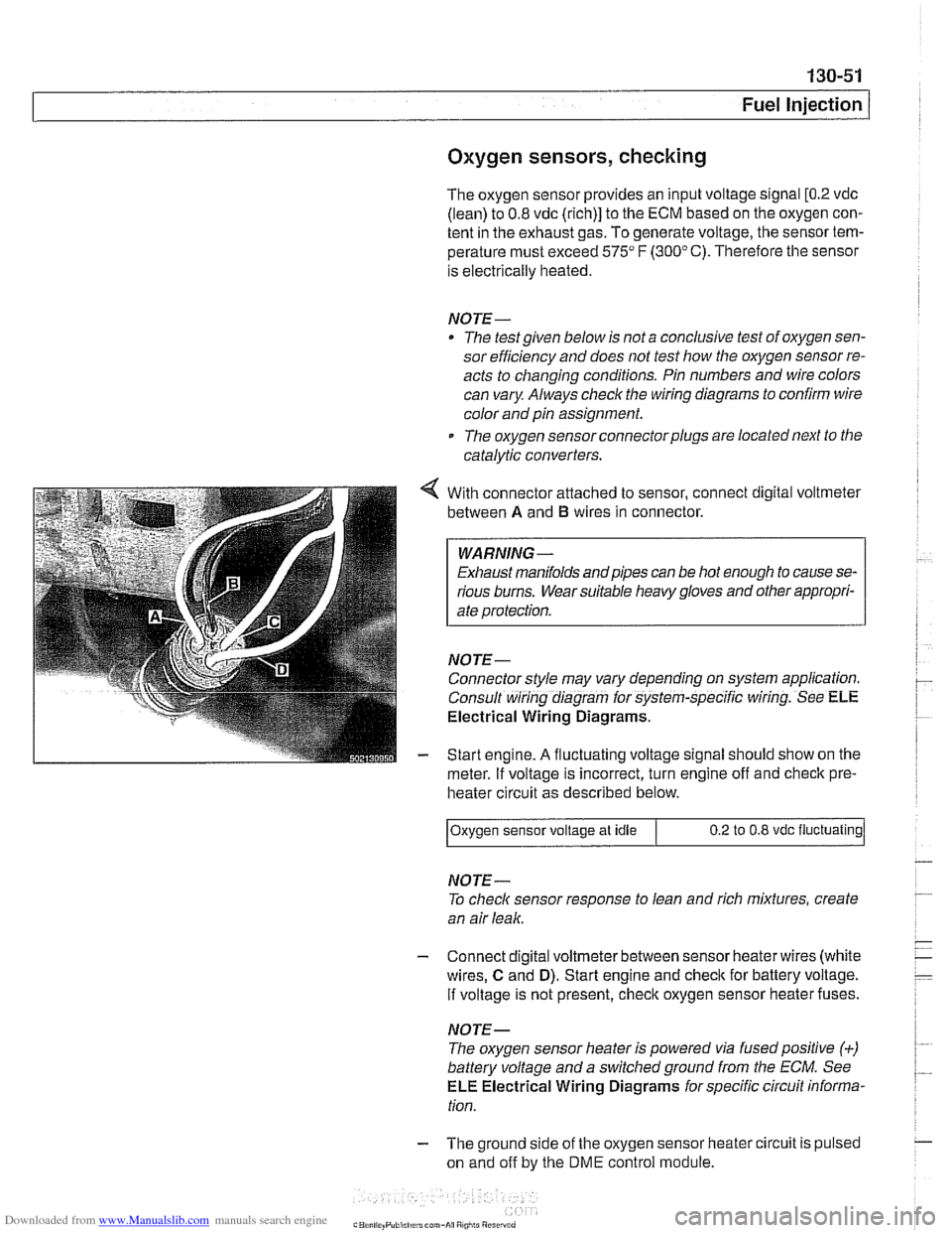
With connector attached to sensor, connect digital voltmeter
between
A and B wires in connector.
WARNING -
Exhaust manifolds andpipes can be hot enough to cause se-
rious burns. Wear suitable heavy gloves and other appropri-
ate protection.
NOJE-
Connector style may vary depending on system application.
Consult wiring diagram for system-specific wiring. See
ELE
Electrical Wiring Diagrams.
Start engine.
A fluctuating voltage signal should show on the
meter.
If voltage is incorrect, turn engine off and check pre-
heater circuit as described below.
NOJE-
To check sensor response to lean and rich mixtures, create
an air leak.
Oxygen sensor
voltage at idle
- Connect digital voltmeterbetween sensor heaterwires (white
wires,
C and D). Start engine and check for battery voltage.
If voltage is not present, check oxygen sensor heater fuses.
0.2 to 0.8 vdc fluctuating
NOJE-
The oxygen sensor heater is powered via fusedpositive (+)
battery voltage and a switchedground from the ECM. See
ELE Electrical Wiring Diagrams for specific circuit informa-
tion.
- The ground side of the oxygen sensor heater circuit is pulsed
on and off by the
DME control module.
Page 477 of 1002
![BMW 540i 1999 E39 Workshop Manual Downloaded from www.Manualslib.com manuals search engine
- Fuel Tank and Fuel pump]
Remove fuel pump
relay (arrow).
4 Connect relay socitet terminal 6 (redlviolet wire) to relay
socket termi BMW 540i 1999 E39 Workshop Manual Downloaded from www.Manualslib.com manuals search engine
- Fuel Tank and Fuel pump]
Remove fuel pump
relay (arrow).
4 Connect relay socitet terminal 6 (redlviolet wire) to relay
socket termi](/img/1/2822/w960_2822-476.png)
Downloaded from www.Manualslib.com manuals search engine
- Fuel Tank and Fuel pump]
Remove fuel pump
relay (arrow).
4 Connect relay socitet terminal 6 (redlviolet wire) to relay
socket terminal
2 (whitelblue wire) with a fused jumper wire.
After completing tests, remove jumper harness.
CA
UTIOG
Relay locations may vary Use care when identifying relays
and making electrical checks at
the fuse/relay panel. See
610 Electrical Component Locations for additional re-
lay information.
The fuel pump relay has a 1.5
md red/violet wire at
terminal
6 in the relay socket. Terminal2 has a 2.5md
white/blue wire. See ELE Electrical Wiring Diagrams
for additional wiring information.
NOTE-
* The fuel pump will run as soon as the jumper wire Is at-
tached.
The jumper wire should be 1.5
md (14 ga.) and include
an in-line fuse holder with a 15A fuse. To avoid
fuse/relay
panel damage from repeated connecting and disconnect-
ing, also include a toggle switch in the jumper harness.
- If pump does not run with jumper installed, fault could be in
fuel pump, fuses
F31 or F22 1 F54, or wiring to pump. Check
pump, fuses and its wiring as described below.
Fuel pump electrical circuit, testing
- The test given below assumes that the fuel pump relay circuit
is functioning correctly as described earlier. Access to the
pump is from below the rear seat bottom cushion.
- Remove rear seat lower cushion by lifting front edge off left
and right catches.
Page 995 of 1002
Downloaded from www.Manualslib.com manuals search engine
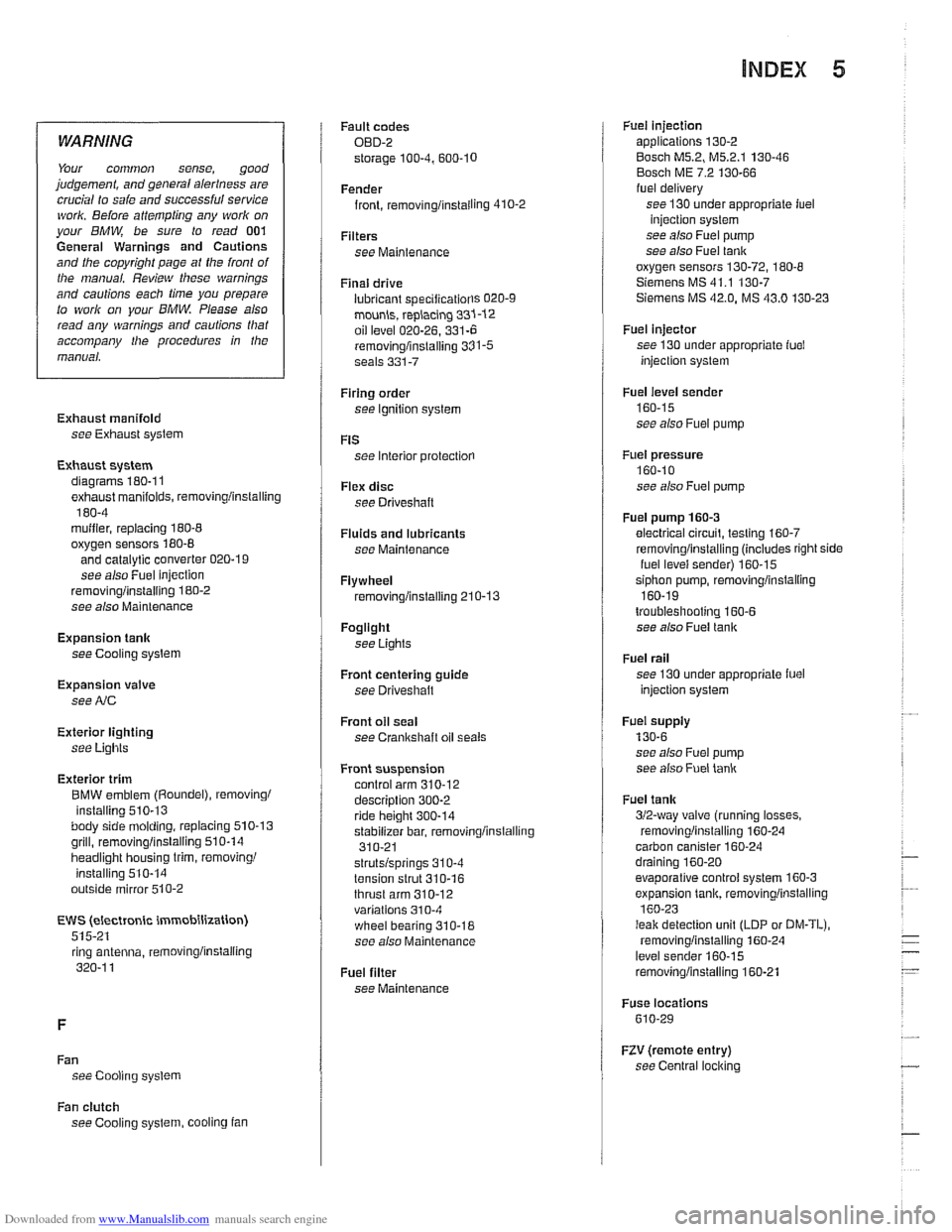
INDEX 5
WARNING
Your common sense, good
judgement, and general alerlness are
crucial lo
safe and successful service ivork. Before attempling any work on
your
BMW be sure lo read 001
General Warnings and Cautions
and the copyright page at the
fronl of
Ihe manual. Review these warnings
and
cautions each lime you prepare
to work on your BMW Please also
read any warnings and cautions tliat
accompany Nie procedures in the
manual.
Exhaust manifold see Exhaust system
Exhaust system diagrams
180.1 1
exhaust manifolds, removinglinstalling
180-4 muifier, replacing 180-8
oxygen sensors 180-8
and catalytic converter 020-1 9
see also Fuel injection
removinglinstalling 180-2
see also Maintenance
Expansion tank
see Cooling system
Expansion valve
see
NC
Exterior lighting
see
Lights
Exterior trim
BMW emblem
(Roundel), removing1
installing
510-13 body side molding, replacing 510.13
grill, removinglinsialiing 510-14
headlight housing trim, removing1
installing 510-14
outside mirror
510-2
EWS (electronic immobilization)
515-21 ring antenna,
iemovinglinstaiting
320-1 1
Fan see Cooling system Fault
codes
OBD-2
storage
100-4. 600.10
Fender
front, rernovinglinstailing
410-2
Filters see Maintenance
Final drive
lubricant
speciiicatiorls 020-9
mounh, replacing 331-12
oil level 020-26. 331-6
removinglinslalling 331-5 seals 331-7
Firing order
see Ignition system
FtS
see Interior protectiorl
Flex disc
see Driveshaft
Fluids and lubricants see Maintenance
Flywheel removinglinstalling 210-13
Fogllght
see Lights
Front centering guide see Driveshatt
Front oil seal
see
Crankshaft oil seals
Front suspension control arm
310-12 description 300-2
ride height 300-14
stabilizer bar, removinglinstalling
310-21
strutslsprings 31
0-4
tension strut 310-16
thrust arm 310-12 variations 310-4
wheel bearing 310-18
see also Maintenance
Fuel filter
see Maintenance
Fuet injection applications 130-2
Bosch M5.2, M5.2.1 130-46
Bosch ME 7.2 130-66 fuel delivery
see 130 under appropriate iuel
injection system
see also Fuel pump
see also
Fuet tank
oxygen sensors
130-72, 180-8
Siemens MS 41.1 130-7 Siemens MS 42.0. MS 43.0 130-23
Fuel injector
see 130 under appropriate fuel
injection system
Fuel level sender
160-15
see also Fuei pump
Fuel pressure
160-10
see also Fuel pump
Fuel pump
160-3
electrical circuit, testino 160-7
1
removinglinstalling (includes right side
iuel levei sender) 160-15
siphon pump, removinglinstaliing
160-19
troubleshooting 160-6 see also Fuel tank
Fuel rail
see 130 under appropriate iuel
injection system
Fuei supply
130-6
see also Fuei pump
see also
Fuet lank
Fuel
tank
312-way valve (running losses.
removinglinstalling
160-24 carbon canister 160-24
draining 160-20
evaporative control system 160-3
expansion tank, removinglinstalling
160-23
I
leak detection unit (LDP or DM-TL),
rernovinoiinstallino 160-24
level senier 160-15
removinglinstalling 160-21
Fuse locations
610-29
RV (remote entry)
see Central
locl(ing
Fan clutch
see Cooling system, cooling fan