change time BMW 540i 2000 E39 User Guide
[x] Cancel search | Manufacturer: BMW, Model Year: 2000, Model line: 540i, Model: BMW 540i 2000 E39Pages: 1002
Page 101 of 1002
Downloaded from www.Manualslib.com manuals search engine
. .- . --
Lr -- - - - -- Cylinder Head Removal and Installation I -
- Release pressure at compression gauge valve, then remove
gauge from spark plug hole. Repeat test for each cylinder
and compare results with values given in Table a.
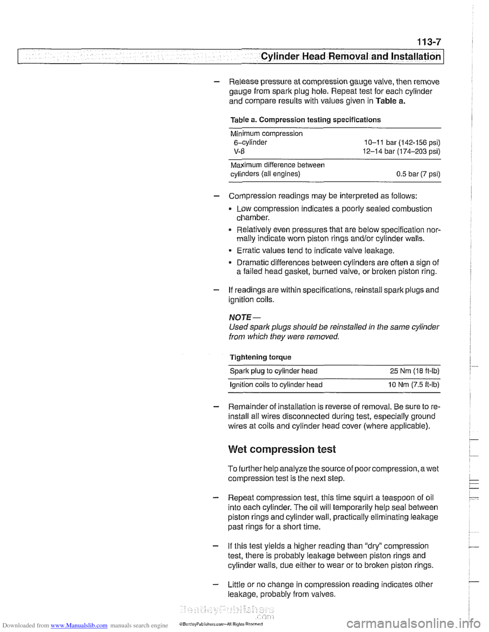
Table a. Compression testing specifications
Minimum compression
6-cylinder
10-1 1 bar (142-156 psi)
V-8 12-14 bar (174-203 psi)
Maximum difference between
cylinders (all engines)
0.5 bar (7 psi)
- Compression readings may be interpreted as follows:
Low compression indicates a poorly sealed combustion
chamber.
0 Relatively even pressures that are below specification nor-
mally indicate worn piston rings
andlor cylinder walls.
Erratic values tend to indicate valve leakage.
Dramatic differences between cylinders are often a sign of
a failed head
gasket, burned valve, or broken piston ring.
- If readings are within specifications, reinstall spark plugs and
ignition coils.
NOTE-
Used spark plugs should be reinstalled in the same cylinder
from which they were removed.
Tightening torque Spark plug to cylinder head 25 Nm
(18 ft-lb)
lanition coils to cylinder head 10 Nm (7.5 ft-lb)
- Remainder of installation is reverse of removal. Be sure to re-
install all wires disconnected during test, especially ground
wires at coils and cylinder head cover (where applicable).
Wet compression test
To further help analyze the source of poorcompression,awet
compression test is the next step.
- Repeat compression test, this time squirt a teaspoon of oil
into each cylinder. The oil will temporarily help seal between
piston rings and cylinder wall, practically eliminating leakage
past rings for a short time.
- If this test yields a higher reading than "dry" compression
test, there is probably leakage between piston rings and
cylinder walls, due either to wear or to broken piston rings.
- Little or no change in compression reading indicates other
leakage, probably from valves.
Page 104 of 1002
Downloaded from www.Manualslib.com manuals search engine
113-10
Cylinder Head Removal and Installation
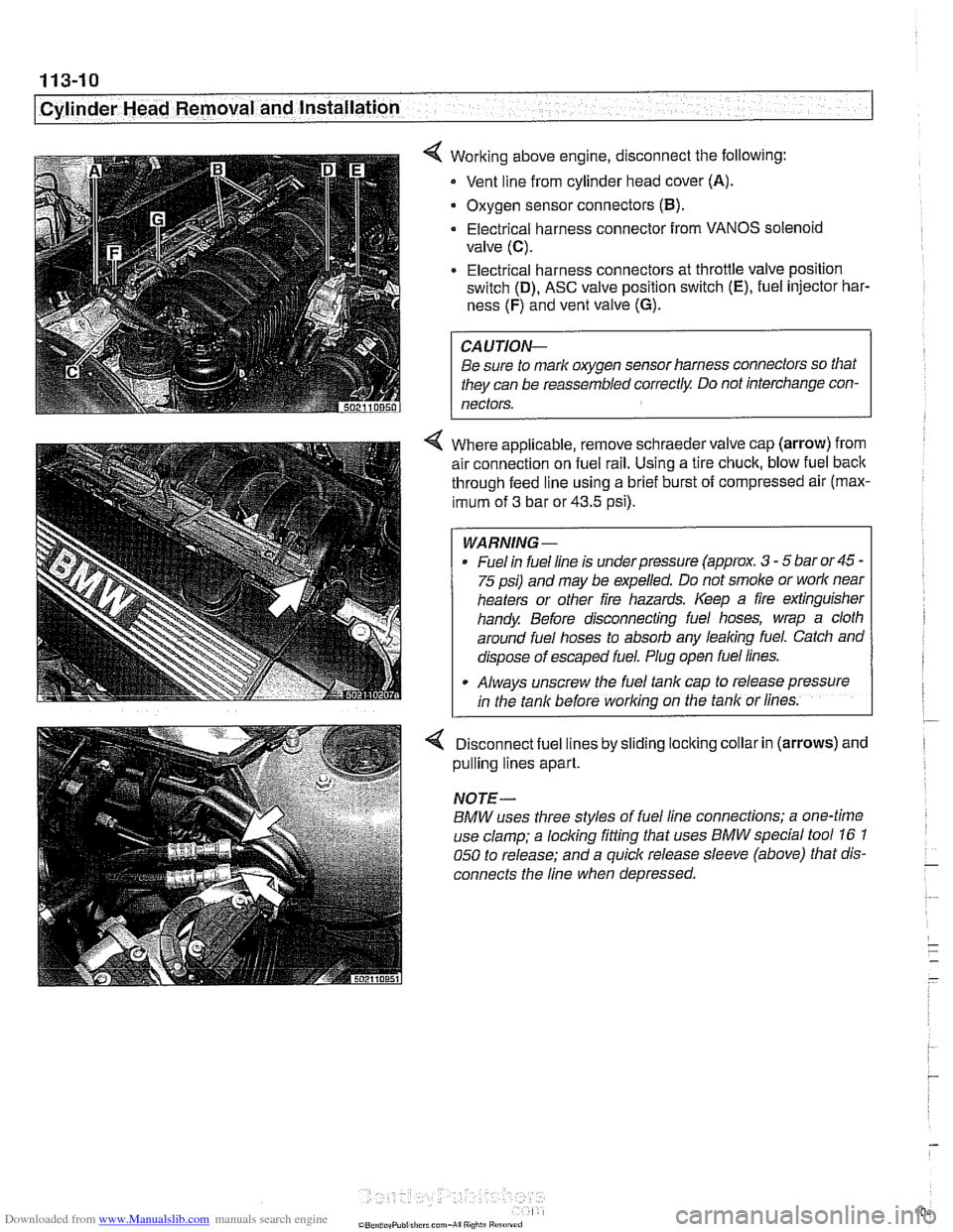
4 Working above engine, disconnect the following:
Vent line from cylinder head cover
(A).
. Oxygen sensor connectors (B).
Electrical harness connector from VANOS solenoid
valve
(C).
Electrical harness connectors at throttle valve position
switch
(D), ASC valve position switch (E), fuel injector har-
ness
(F) and vent valve (G).
CAUTION-
Be sure to mark oxygen sensor harness connectors so that
they can be reassembled correctly Do not interchange con-
nectors.
4 Where applicable, remove schraeder valve cap (arrow) from
air connection on fuel rail. Using a tire chuck, blow fuel back
through feed line using a brief burst of compressed air (max-
imum of
3 bar or 43.5 psi).
WARNING-
. Fuel in fuel line is underpressure (approx. 3 - 5 bar or 45 -
75 psi) and may be expelled. Do not smoke or work near
heaters or other fire hazards. Keep a fire extinguisher
handy Before disconnecting fuel hoses, wrap a cloth
around fuel hoses to absorb any leaking fuel. Catch and
dispose of escaped fuel. Plug open fuel lines.
- Always unscrew the fuel rank cap ro release pressure
;n the tank before working on the tank or lines.
Disconnect fuel lines by sliding locking collar in (arrows) and
pulling lines apart.
NOTE-
BMW uses three styles of fuel line connections; a one-time
use
clamp; a locking fitting that uses BMWspecial tool 16 1
050 to release; and a quick release sleeve (above) that dis-
connects the line when depressed.
Page 401 of 1002
Downloaded from www.Manualslib.com manuals search engine
Fuel Injection
CAUTION-
Be sure ignition is OFF before disconnecting or reconnecting
DME system components.
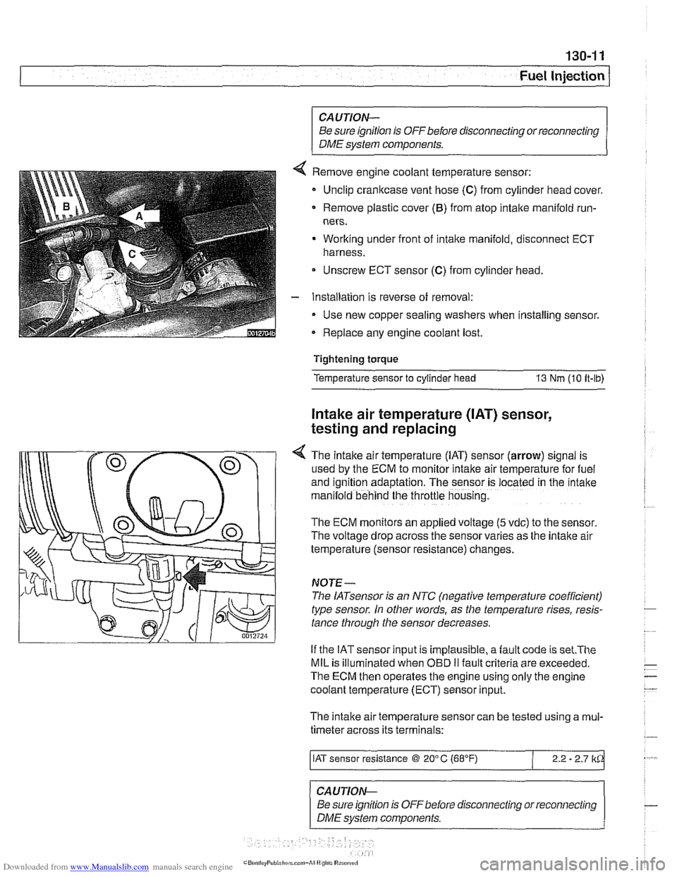
Remove engine coolant temperature sensor:
Unclip crankcase vent hose
(C) from cylinder head cover.
Remove plastic cover
(6) from atop intake manifold run-
ners.
Working under front of intake manifold, disconnect ECT
harness.
Unscrew ECT sensor
(C) from cylinder head.
Installation is reverse of removal:
Use new copper sealing washers when installing sensor.
Replace any engine coolant lost.
Tightening torque
Temperature sensor to cylinder head
13 Nm (10 it-lb)
Intake air temperature ([AT) sensor,
testing and replacing
4 The intake air temperature (IAT) sensor (arrow) signal is
used by the ECM to monitor intake air temperature for fuel
and
igntion adaptation. The sensor is .ocared in rne 'ntane
man:lold behind the throttle housng.
The ECM monitors an applied voltage (5 vdc) to the sensor
The voltage drop across the sensor varies as the intake air
temperature (sensor resistance) changes.
NOJE-
The IATsensor is an NTC (negative temperature coefficient)
type sensor. In other words, as the temperature rises, resis-
tance through the sensor decreases.
If the IAT sensor input is implausible, a
fault code is set.The
MIL is illuminated when OED II fault criteria are exceeded.
The ECM then operates the engine using only the engine
coolant temperature (ECT) sensor input.
The intake air temperature sensor can be tested using a
mul-
timeter across its terminals:
/ IAT sensor resistance @ 20" C (68°F) / 2.2 - 2.7 lkCk
~ -- ~~ -
CAUTION--
Be sure ignition is
OFFbefore disconnecting or reconnecting
DME system components.
Page 420 of 1002
Downloaded from www.Manualslib.com manuals search engine
Fuel Injection
Engine coolant temperature
(ECT) sensor,
testing and replacing
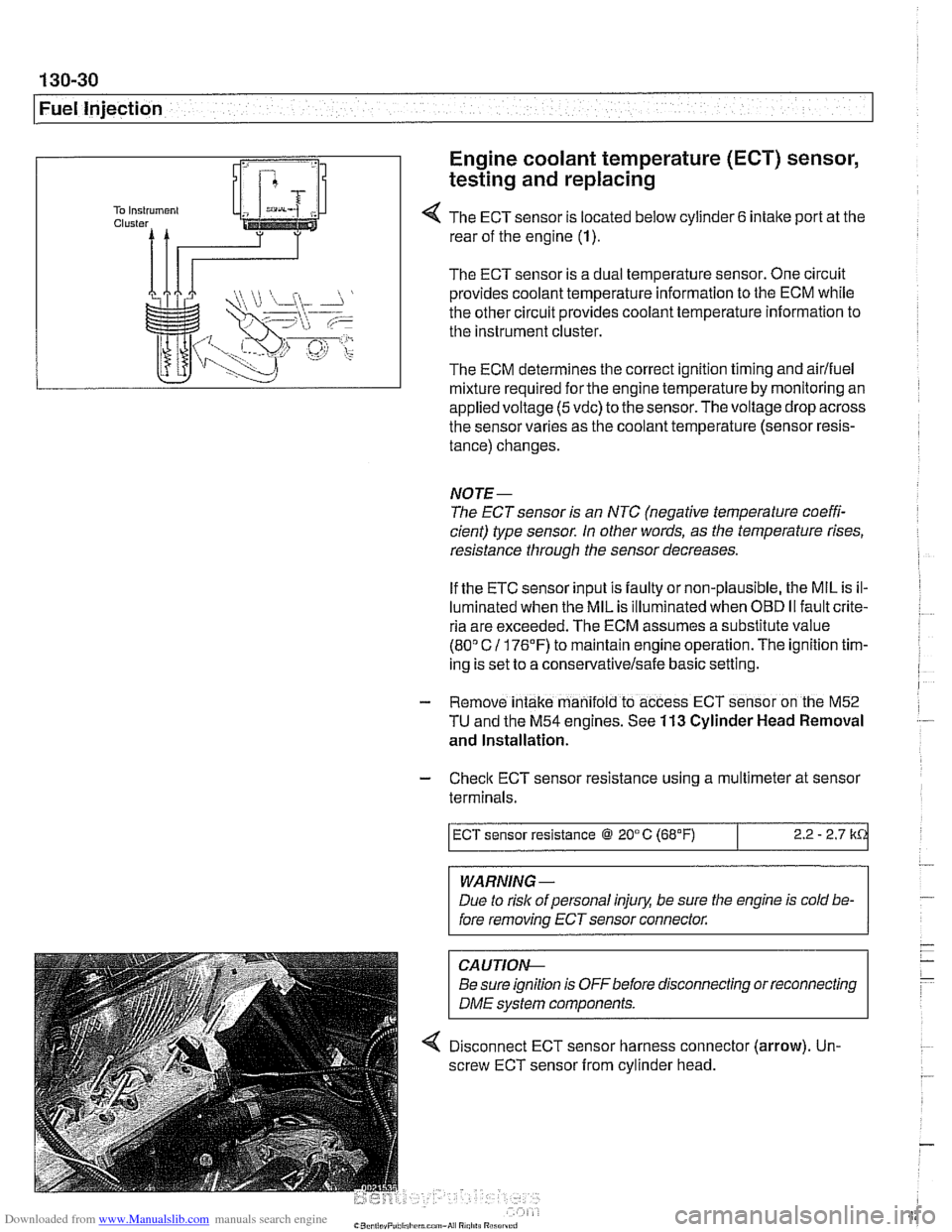
4 The ECT sensor is located below cylinder 6 intake port at the
rear of the engine (1).
The ECT sensor is a dual temperature sensor. One circuit
provides coolant temperature information to the ECM while
the other circuit provides coolant temperature information to
the instrument cluster.
The ECM determines the correct ignition timing and airlfuel
mixture required
forthe engine temperature by monitoring an
appliedvoltage
(5vdc) to the sensor.Thevoltage drop across
the sensor varies as the coolant temperature (sensor resis-
tance) changes.
NOTE-
The ECT sensor is an NTC (negative temperature coeffi-
cient) type sensor. In other words, as the temperature rises,
resistance through the sensor decreases.
If the ETC sensor input is faulty or non-plausible, the MIL is il-
luminated when the MIL is illuminated when
OED II fault crite-
ria are exceeded. The ECM assumes a substitute value
(80" C 11 76'F) to maintain engine operation. The ignition tim-
ing is set to a
conservativelsafe basic setting.
- Remove intake manifold to access ECT sensor on the M52
TU and the M54 engines. See 113 Cylinder Head Removal
and Installation.
- Check ECT sensor resistance using a multimeter at sensor
terminals.
WARNING -
Due to rislc of personal injury, be sure the engine is cold be-
fore removing ECT sensor connector.
ECT sensor resistance @ 20°C (68°F)
CAUTIOI\C
Be sure ignition is OFFbefore disconnecting or reconnecting
DME svstem components.
2.2 - 2.7 k
4 Disconnect ECT sensor harness connector (arrow). Un-
screw ECT sensor from cylinder head.
Page 570 of 1002
Downloaded from www.Manualslib.com manuals search engine
230-6
Manual Transmission
Manual transmissions installed in the 5 Series are normally
filled with a "Lifetime" manual transmission fluid
(BMW MTF
LT-I) and do not require periodic fluid changes. Transmis-
sions filled with MTF LT-I lifetime oil are identified with a yel-
low label near the transmission fill plug labeled "Lifetime Oil
MTF-LT-1".
Transmission fluid level, checking
- Drive vehicle for a few miles to warm transmission.
- Raise and safely support vehicle to access transmission
filler plug.
CAUTION-
Make sure the car is stable and well supporfedat all times.
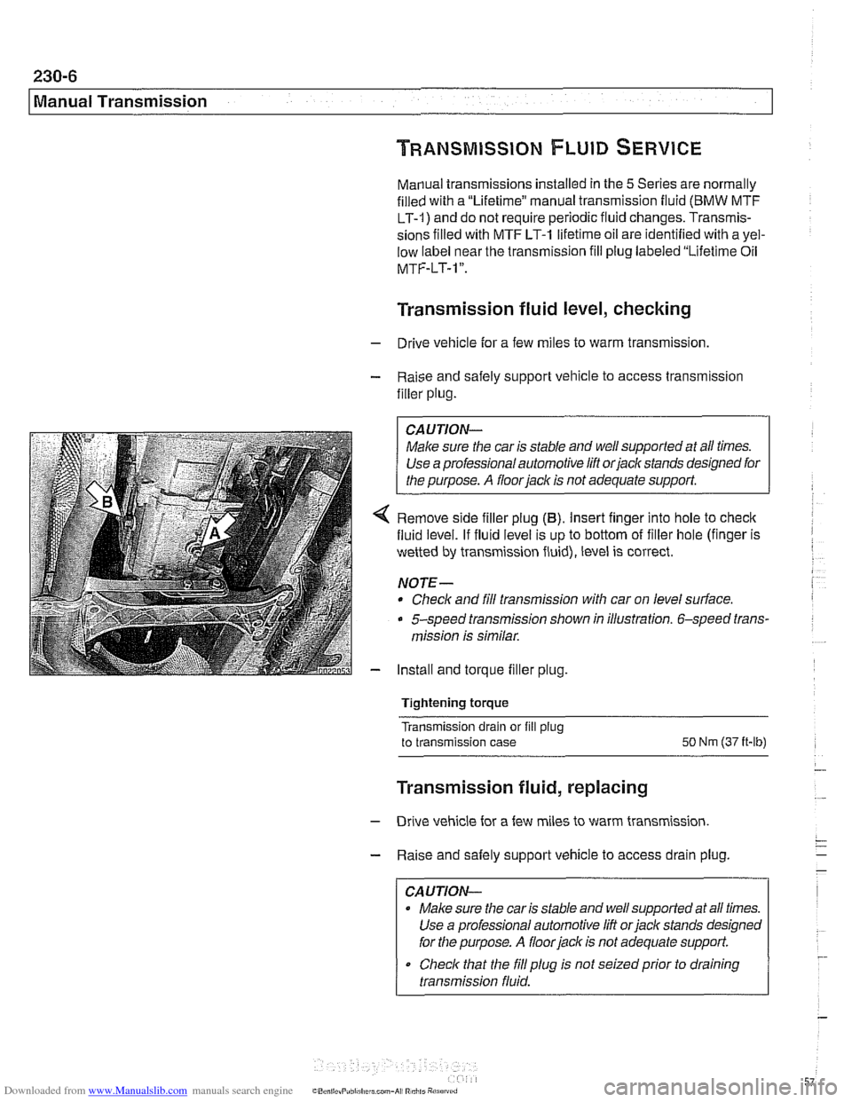
4 Remove side filler plug (B). Insert finger into hole to check
fluid level. If fluid level is up to bottom of filler hole (finger is
wetted by transmission fluid), level is correct.
NOTE-
* Check and fill transmission with car on level surface.
5-speed transmission shown in illustration. 6-speed trans-
mission is similar.
- Install and torque filler plug.
Tightening torque
Transmission drain or fill
plug
to transmission case SO Nm (37 it-lb)
Transmission fluid, replacing
- Drive vehicle for a few miles to warm transmission.
- Raise and safely support vehicle to access drain plug.
CAUTION-
Make sure the car is stable and well supported at all times.
Use a professional automotive lift
orjack stands designed
for the purpose.
A floor jack is not adequate support.
Check that the
fill plug is not seizedprior to draining
transmission fluid.
Page 750 of 1002
Downloaded from www.Manualslib.com manuals search engine
Final Drive
Tightening torques
F~nal drive to rear axle carrier 105 Nm (77 it-lb)
Driveshaft CV joint to final drive flange
- MlO (Torx bolt) 70
Nm (51 ft-lb)
- M8 (compression nut) 32 Nm (24
ft-lb)
Drive axle to final drive
ilange
Torx bolts (M10) 83 Nm (61 ft-lb)
Torx bolt with
rlbbed teeth (M10) 64 Nm (47 ft-lb)
Torx bolt
wlth ribbed teeth (MI0 sliver) 80 Nm (59 ft-lb)
Torx
bolt with ribbed teeth (M10 black) 100 Nm (74 ft-lb)
* Torx bolt with ribbed teeth (M12) 135 Nm (100 ft-lb)
Differential oil level, checking
The E39 differential is filled with lifetime oil that ordinarily
does not need to be changed. BMW recommends using only
a specially formulated synthetic gear oil
(SAF-XO) that is
available through an authorized BMW dealer parts depart-
ment. For additional information on this lubricant and any oth-
er lubricants that may be compatible, contact an authorized
BMW dealer service department.
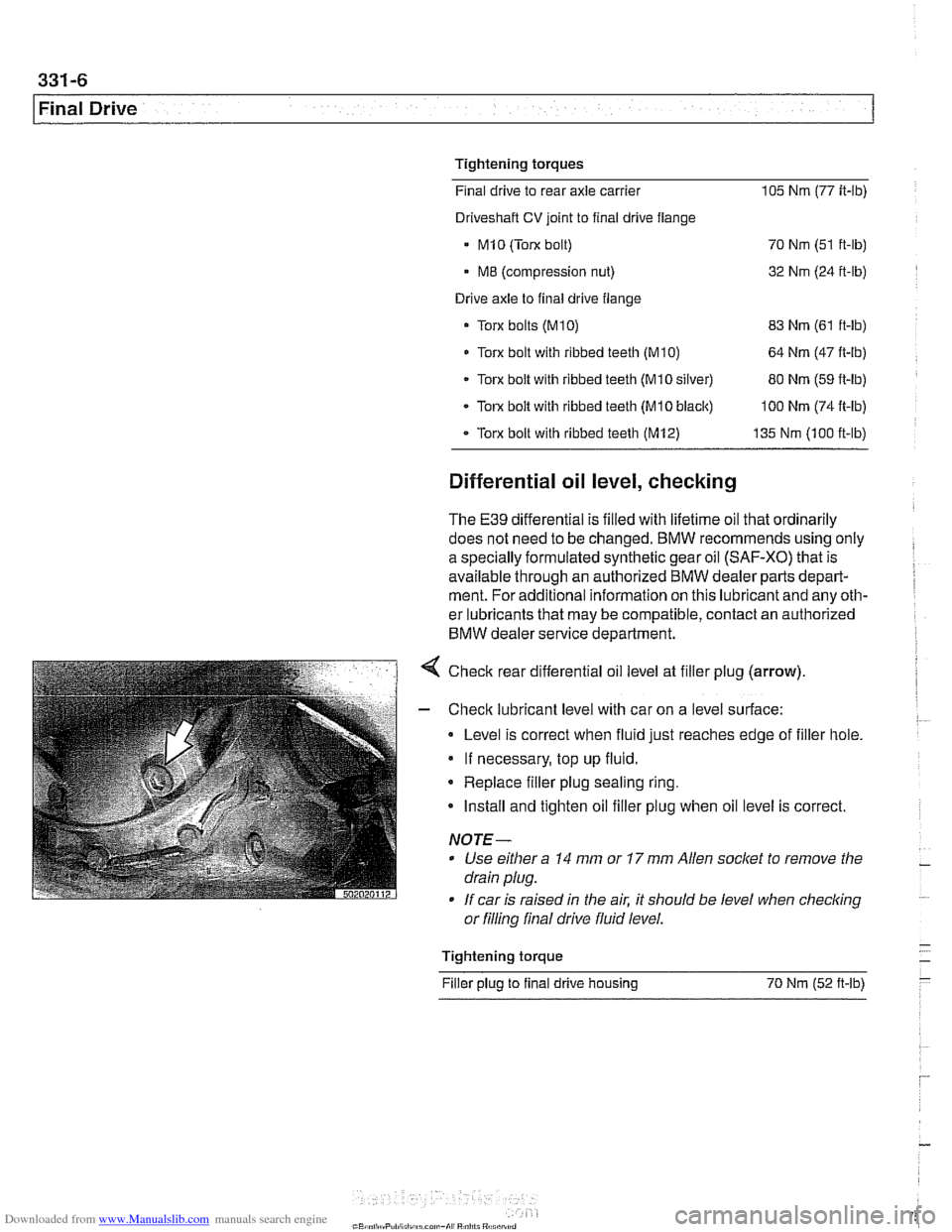
< Check rear differential oil level at filler plug (arrow).
- Check lubricant level with car on a level surface:
Level is correct when fluid just reaches edge of filler hole.
If necessary, top up fluid.
* Replace filler plug sealing ring.
Install and tighten oil filler plug when oil level is correct.
NOTE-
Use either a 14 mm or 17 mm Allen socket to remove the
drain plug.
If car is raised in the air. it should be level when
checkino " or filling final drive fluid level.
- Tightening torque -
Filler plug to final drive housing 70 Nm (52
ft-lb) -
Page 905 of 1002
Downloaded from www.Manualslib.com manuals search engine
515-11
Central Lockinq and ~nti-l heft/
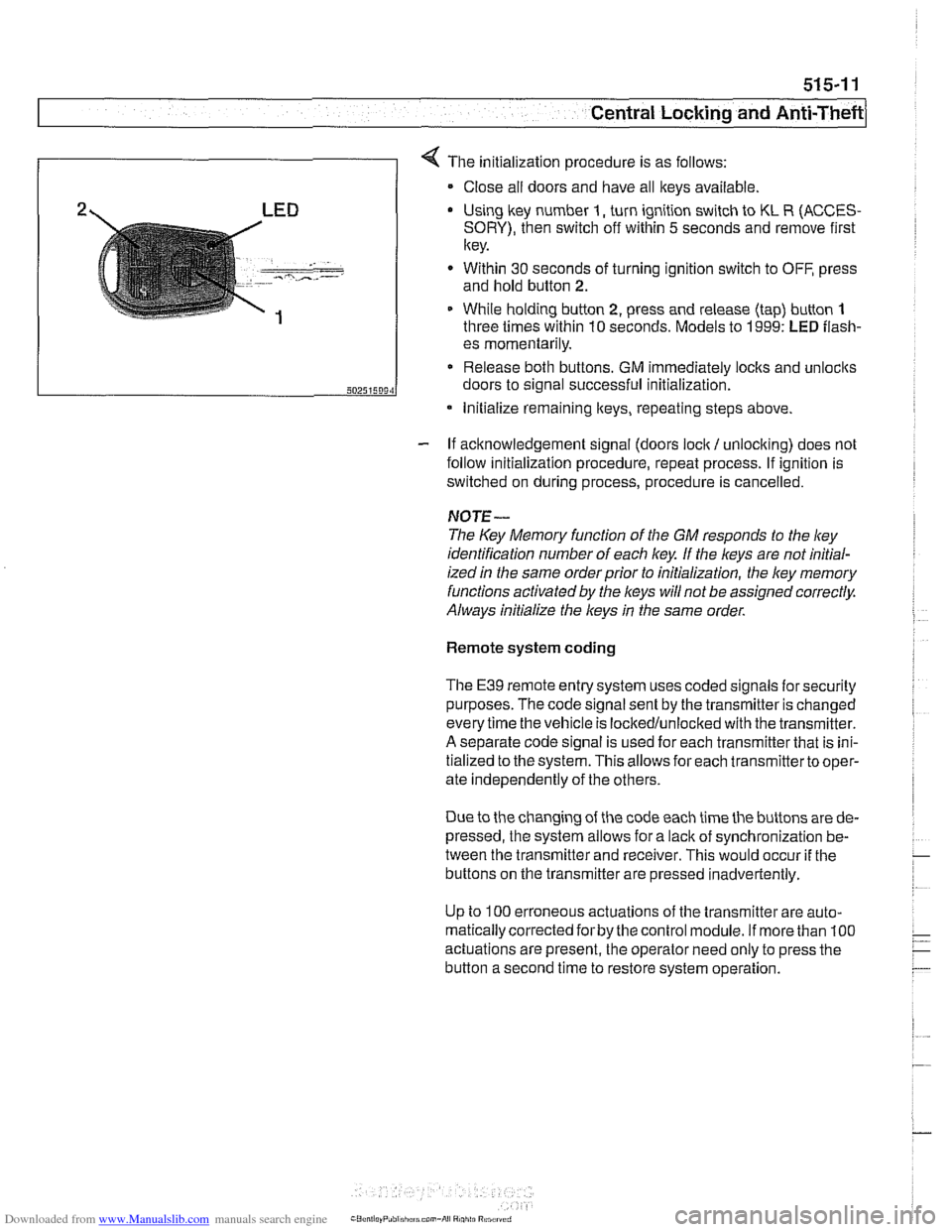
4 The initialization procedure is as follows:
Close ail doors and have all keys available
2 LED Using lkey number I, turn ignition switch to KL R (ACCES-
SORY), then switch off within 5 seconds and remove first
key.
. - -- , ..-.---- - Within 30 seconds of turning ignition switch to OFF, press
and hold button
2.
1 While holding button 2, press and release (tap) button 1
three times within 10 seconds. Models to 1999: LED flash-
- If acknowledgement signal (doors lock / unlocking) does not
follow initialization procedure, repeat process. If ignition is
switched on during process, procedure is cancelled.
50251509‘1
NOTE-
The Key Memory function of the GM responds to the ley
identification number of each key If the keys are not initial-
ized
in the same orderprior to initialization, the ley memory
functions activated by the
l(eys will not be assigned correctly.
Always initialize the keys
in the same order.
es momentarily.
Release both buttons. GM immediately locks and unlocits
doors to signal successful initialization.
Remote system coding
* Initialize remaining lteys, repeating steps above.
The E39 remote entry system uses coded signals for security
purposes. The code signal sent by the transmitter is changed
every time the vehicle is lockedlunlocked with the transmitter.
A separate code signal is used for each transmitter that is ini-
tialized to the system. This allows for each transmitterto oper-
ate independently of the others.
Due to the changing of the code each time the buttons are de-
pressed, the system allows for a
lacit of synchronization be-
tween the transmitter and receiver. This would occur
if the
buttons on the transmitter are pressed inadvertently.
Up to
100 erroneous actuations of the transmitter are auto-
matically corrected
forby the control module. If more than 100
actuations are present, the operator need only to press the
button a second time to restore system operation.
Page 919 of 1002
Downloaded from www.Manualslib.com manuals search engine
51 5-25
Central Lockina and ~nti-~heftl
1
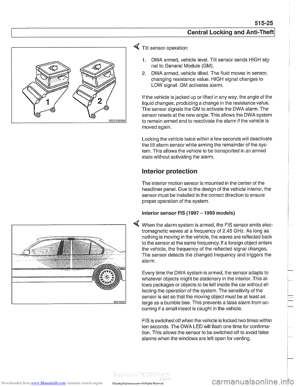
Tilt sensor operation:
1. DWA armed, vehicle level. Tilt sensor sends HlGH sig-
nal to General Module (GM).
2. DWA armed, vehicle tilted. The fluid moves in sensor,
changing resistance value.
HlGH signal changes to
LOW signal. GM activates alarm.
If the vehicle is jacked up or lifted in any way, the angle of the
liquid changes, producing a change in the resistance value.
The sensor signals the GM to activate the DWA alarm. The
sensor resets at the new angle.
This allows the DWA system
to remain armed and to reactivate the alarm if tlie vehicle is
moved again
Locking the vehicle twice within a few seconds will deactivate
the tilt alarm sensor while arming tlie remainder of the sys-
tem. This allows the vehicle to be transported in an armed
state without activating tlie alarm.
Interior protection
The interior motion sensor is mounted in the center of the
headliner panel. Due to the design of the vehicle interior, the
sensor must be installed in the correct direction to ensure
proper operation of the system.
lnterior sensor FIS (1997 - 1999 models)
4 When the alarm system is armed, the FIS sensor emits elec-
tromagnetic waves at
a frequency of 2.45 GHz. As long as
nothing is moving in the vehicle, the waves are reflected
baclc
to the sensor at the same frequency. If a foreign object enters
the vehicle, the frequency of the reflected signal changes.
The sensor detects the changed frequency and triggers the
alarm.
Every time the DWA system is armed, the sensor adapts to
whatever objects might be stationary in the interior. This al-
lows pacltages or objects to be left inside tlie car without ef-
fecting the operation of the system. The sensitivity of the
sensor is set so that the moving object must be at least as
large as a bumble bee. This prevents a false alarm from oc-
curring if a small insect is caught in the vehicle.
FIS is switched off when the vehicle is locked two times within
ten seconds. The DWA LED will flash one time for confirma-
tion. This allows the sensor to be switched off to avoid false
alarms when the windows are left open for venting.
Page 920 of 1002
Downloaded from www.Manualslib.com manuals search engine
51 5-26
Central Locking and Anti-Theft
Interior sensor UIS (2000 and later models)
The
UIS system uses ultrasonic sound waves instead of elec-
tromagnetic waves. Ultrasonic sound waves are less suscep-
tible to magnetic interference.
Every time the DWA system is armed, the sensor adapts to
whatever objects might be stationary in the interior. The sen-
sor emits ultrasonic waves in a programmed timed cycle. It re-
ceives echoes of the emitted waves. The
UIS amplifies the
received sound wave signals and compares them to the ech-
oes of the transmitted waves. The
UIS also checits the incom-
ing echoes for background hiss (wind noise through a
partially open window) and adapts for this.
If the echoes are consistently similar, no movement is de-
tected.
If the echoes are altered, (inconsistent), the UIS deter-
mines motion in the interior compartment.
If motion is detected, the
UIS changes to a constant cycle
and the echo is compared again.
If the inconsistency is still present the
UIS sends the acti-
vate siren signal to the GM.
Glass breakage sensors
The doorwindows are monitored by inductive sensors mount-
ed on the inside of the door behind the trim panel. A closed
window is recognized by a magnetic plate
on the glass lining
up with the sensor. If the glass is broken, the plate falls away
and the signal from the sensor changes. This causes the GM
to activate the alarm.
Emergency disarming
- An emergency procedure is provided to cancel the DWA in
the event that a fault occurs within the system. The procedure
is as follows:
Driver's door mechanically
unloclted and open within 30
seconds. This will cause triggering of alarm.
All doors closed.
Ignition switch turned to
KL R (ACCESSORY). LED indica-
tor will come on.
- After 10 minutes, alarm is disarmed
Page 952 of 1002
Downloaded from www.Manualslib.com manuals search engine
I Airbag System (SRS)
Two-stage airbag (MRS Ill)
Beginning with 2000 model year (911 999 production) the front
airbags were changed to a two-stage style airbag. This en-
sures that the force of
airbag inflation is not greater than nec-
essary to provide
protection. The airbags are designed to
Drovide "soit" de~lovment if the acceleration sensor detects a
iow-speed impact, and "hard deployment in higher speed im-
pacts.
NOTE-
A two-stage passenger airbag was used on cars built be-
tween
9/1998 and 3/1999. This pre-smart technology airbag
used two ignition stages. Stage one is designed to ignite first
during an impact. Stage two ignites after a timed period, as
programmed in the MRS
I1 control module.
Airbag indicator light
The MRS control module detects and stores system status
The
airbag indicator light in the instrument cluster displays
the status of the
airbag system when the ignition key is in "ac-
cessory" or
ON positions.
System normal: lndicator light comes on briefly, then goes
out.
- System malfunction: lndicator light fails to come on.
System malfunction: lndicator light comes on briefly, goes
out and lights up again.
The
airbag indicator light also comes on if the seat belt pyro-
technic tensioners have been triggered.