Coolant system BMW 540i 2000 E39 Owner's Manual
[x] Cancel search | Manufacturer: BMW, Model Year: 2000, Model line: 540i, Model: BMW 540i 2000 E39Pages: 1002
Page 214 of 1002
Downloaded from www.Manualslib.com manuals search engine
I Cylinder Head and Valvetrain
- Remove adjustable primary timing chain tensioner tool and
reinstall primary chain tensioner cylinder to cylinder head.
Tightening torque
Primary chain tensioner cylinder
to 70 Nm (52 ft-lb)
cylinder head
- Remove flywheel locking tool from crankcase. Replace spe-
cial tool bore sealing plug.
- Remove camshaft locking tools from cylinder head
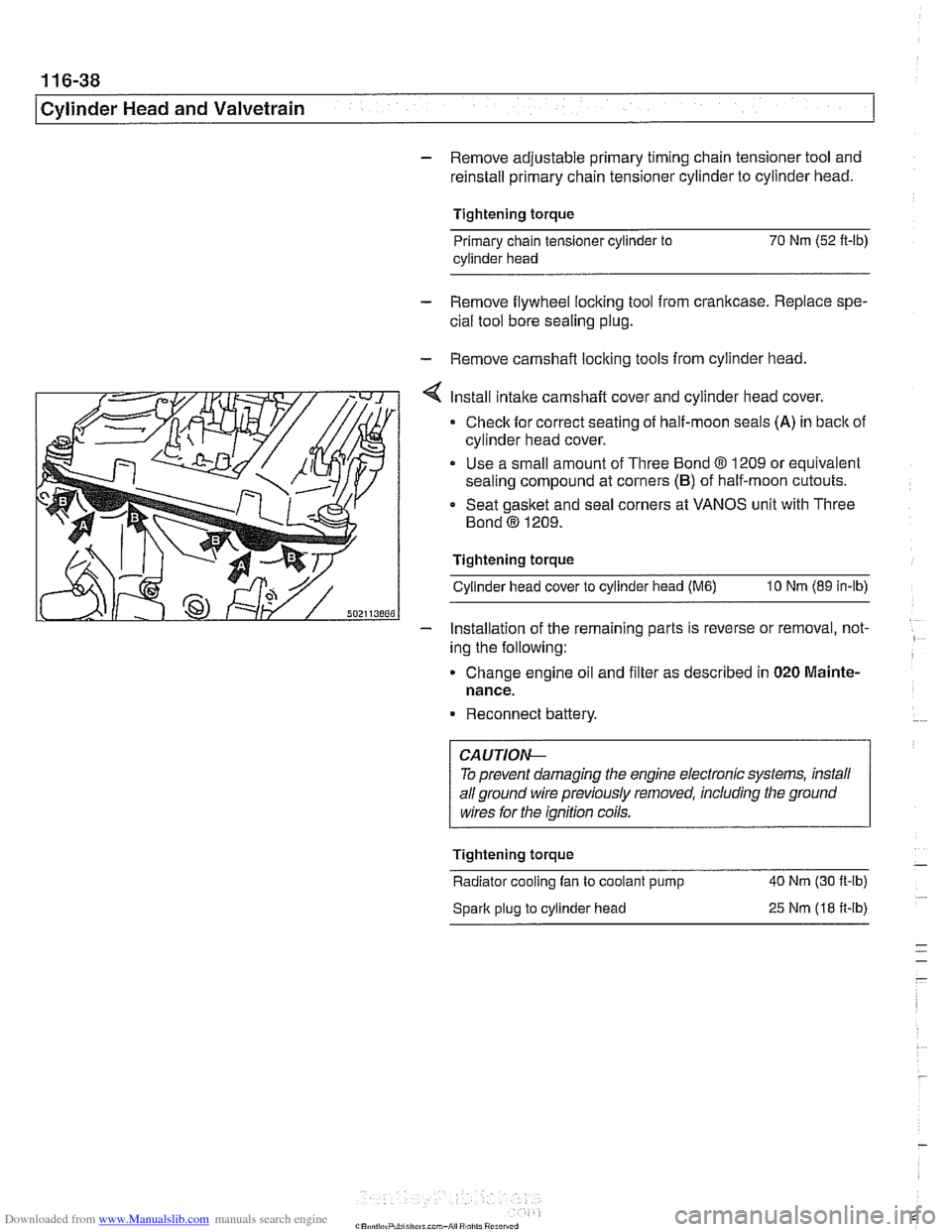
Install intake camshaft cover and cylinder head cover.
Check for correct seating of half-moon seals (A) in back of
cylinder head cover.
Use a small amount of Three Bond
8 1209 or equivalent
sealing compound at corners
(B) of half-moon cutouts.
Seat gasket and seal corners at VANOS unit with Three
Bond
@ 1209.
Tightening torque Cylinder head cover to cylinder head
(M6) 10 Nm (89 in-lb)
- Installation of the remaininq parts is reverse or removal, not- -
ing the following:
Change engine
011 and f~lter as descr~bed in 020 Mainte-
nance.
Reconnect battery.
To prevent damaging the engine electronic systems, install
all ground wire previously removed, including the ground
wires for the ignition coils.
Tightening torque
-
Radiator cooling fan to coolant pump 40 Nm
(30 ft-ib)
Spark plug to cylinder head
25 Nm (18 ft-ib)
Page 215 of 1002
Downloaded from www.Manualslib.com manuals search engine
Cylinder Head and valvetrain1
Camshaft removal and installation
(M62 engine)
Camshafts, removing (M62 engine)
Special
BMW service tools should always be used to remove
and install the camshafts. Removal of the camshafts without
the special tools can result in personal injury and lor cylinder
head damage.
NOTE-
Cylinder bank 1-4 is referred to as the right cylinder bank
and is located on the passenger side. Cylinder bank 5-8 is
referred to as the left cylinder bank and is located on the driv-
er's side.
WARNING-
Allow enqine to cool before beqinninq this procedure. 1
- Disconnect negative (-) cable from battery.
CAUTION-
Prior to disconnecting the battery, read the battery discon-
nection cautions
in 001 General Cautions and Warnings.
- Dra~n coolant. See 170 Radiator and Cooling System.
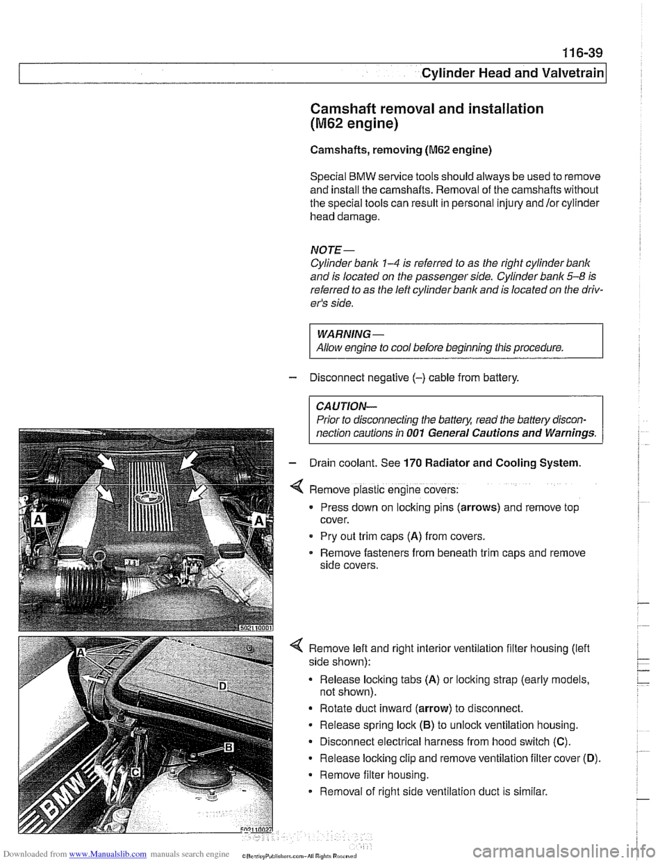
Remove plastic engine covers:
Press down on locking pins (arrows) and remove top
cover.
Pry out
trlm caps (A) from covers.
Remove fasteners from beneath
trlm caps and remove
side covers.
4 Remove left and right interior ventilation filter housing (lefl
side shown):
Release locking tabs
(A) or locking strap (early models,
not shown).
Rotate duct inward (arrow) to disconnect.
- Release spring lock (6) to unloclc ventilation housing.
Disconnect electrical harness from hood switch
(C).
Release locking clip and remove ventilation filter cover (0).
Remove filter housing.
Removal of right side ventilation duct is similar.
Page 262 of 1002
Downloaded from www.Manualslib.com manuals search engine
Camshaft Timing Chain Timing chains, removing
(M52 engine)
Camshaft timing chain removal on M52 engines requires en-
gine oil pan removal.
Special
BMW sewice tools are needed for timing chain re-
moval and installation procedures. The special tools assure
propertiming of thevalvetrain. Precise marks to
setthe timing
on the camshafts are not provided for reassembly. Read the
procedures through before beginning the job.
NOTE-
If the camshafts are not properly timed, the pistons can con-
tact the valves.
- Remove VANOS control unit. See VANOS control unit, re-
moving (M52 engine).
- Remove radiator cooling fan and shroud. See 170 Radiator
and Cooling System.
- Drain cooling system. See 170 Radiator and Cooling Sys-
tem.
- Remove coolant hoses from thermostat housing and remove
thermostat housing from front of cylinder head.
- Loosen bolts for coolant pump pulley.
- Remove drive belts for alternator and AIC compressor. See
020 Maintenance.
- Remove coolant pump pulley.
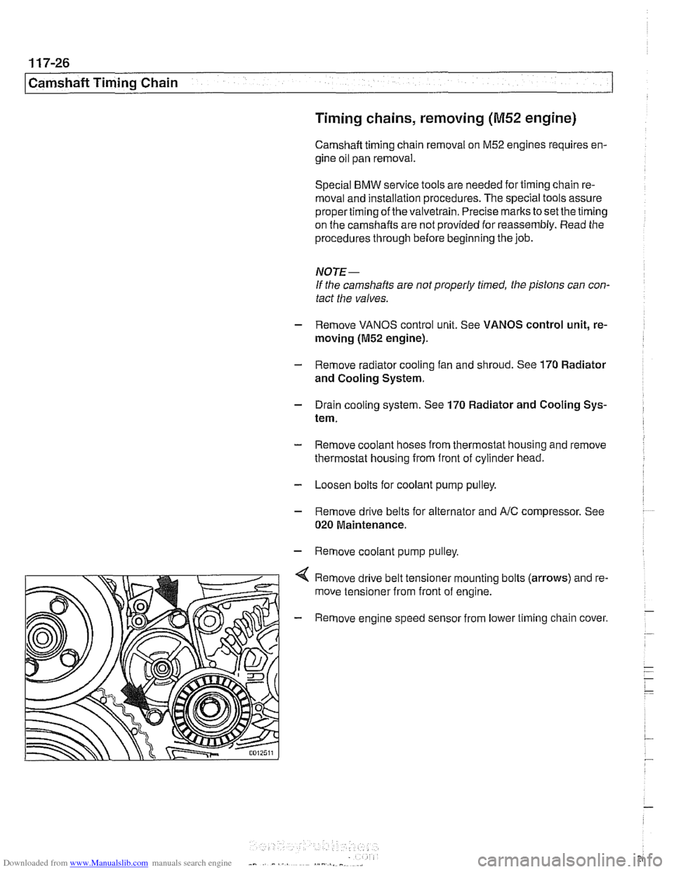
Remove drive belt tensioner mounting bolts (arrows) and re-
move tensioner from front of engine.
- Remove engine speed sensor from lower timing chain cover.
Page 270 of 1002
Downloaded from www.Manualslib.com manuals search engine
1 17-34
1 Camshaft Timing Chain
DOUBLE VAMOS SYSTEM
(M52 TU AND M54 ENGINES)
Double VANOS system function
The M52TU and M54 6-cylinder engines are equipped with a
Double VANOS system that varies intake and exhaust cam-
shaft timing.
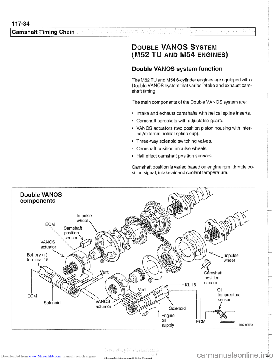
The main components of the Double VANOS system are:
lntalte and exhaust camshafts with helical spline inserts.
Camshaft sprockets with adjustable gears.
VANOS actuators (two position piston housing with
inter-
nallexternal helical spline cup).
Three-way solenoid switching valves.
Camshaft position impulse wheels.
Hall effect camshaft position sensors.
Camshaft position
IS varied based on engine rpm, throttle po-
sition signal, intake air and coolant temperature.
Page 302 of 1002
Downloaded from www.Manualslib.com manuals search engine
11 7-66
I Camshaft Timing Chain
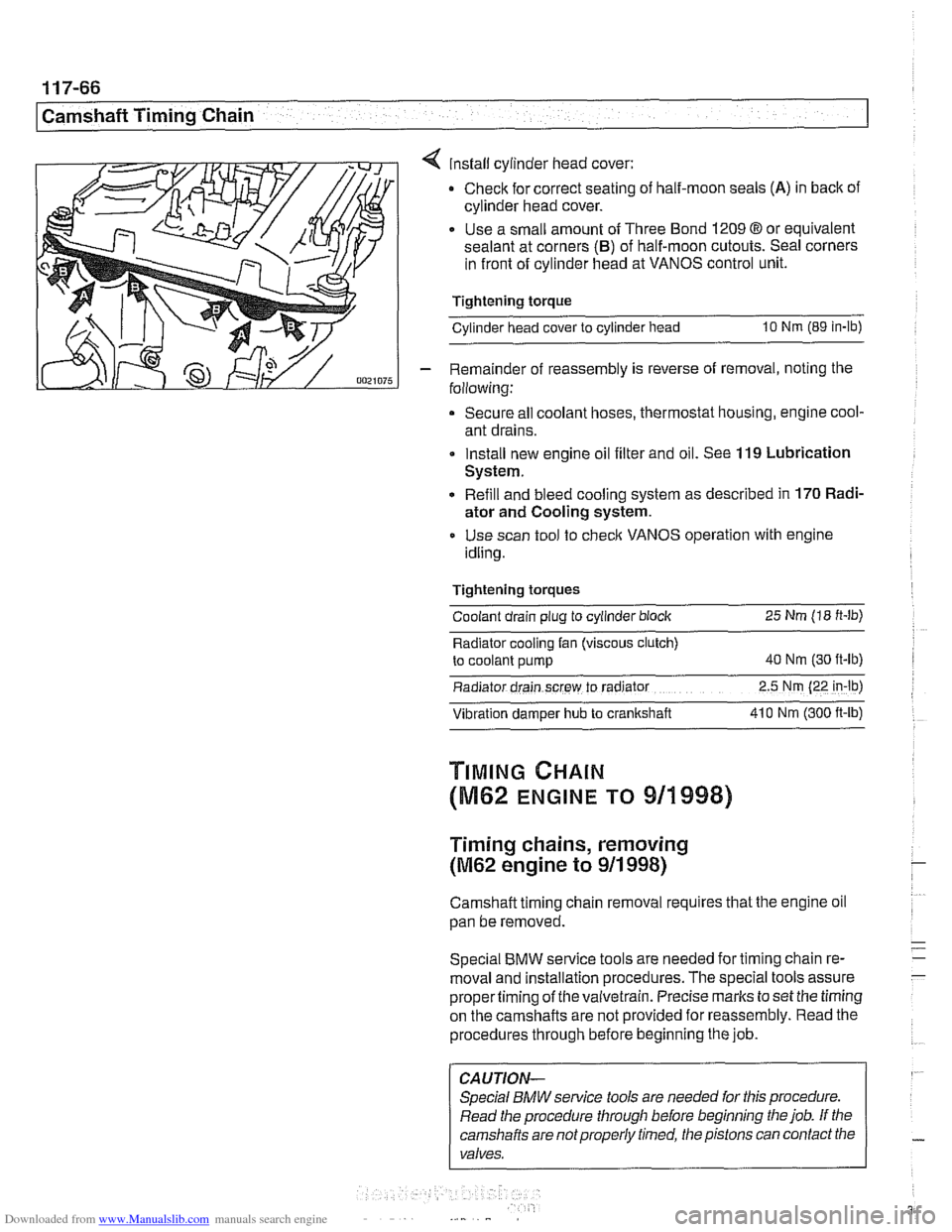
4 install cylinder head cover:
Check for correct seating of half-moon seals
(A) in back of
cylinder head cover.
Use a small amount of Three Bond
1209 8 or equivalent
sealant at corners
(B) of half-moon cutouts. Seal corners
in front of cylinder head at VANOS control unit.
Tightening torque
Cylinder head cover to cylinder head
10 Nm (89 in-lb)
- Remainder of reassembly is reverse of removal, noting the
following:
Secure all coolant hoses, thermostat housing, engine cool-
ant drains.
Install new engine oil filter and oil. See
119 Lubrication
System.
Refill and bleed cooling system as described in
170 Radi-
ator and Cooling system.
Use scan tool to check VANOS operation with engine
idling.
Tightening torques Coolant drain plug to cylinder block
25 Nm (18 ft-lb)
Radiator cooling fan (viscous clutch)
to coolant pump
40 Nm (30 ft-lb)
Radiator drain screw to radrator 2.5 Nm (22 in-lb)
Vibration damper hub to crankshaft 41 0 Nm
(300 ft-ib)
TIMING CHAIN
(M62 ENGINE TO 911998)
Timing chains, removing
(M62 engine to 911 998)
Camshaft timing chain removal requires that the engine oil
pan be removed.
Special
BMW service tools are needed for timing chain re-
moval and installation procedures. The special tools assure
propertiming of thevaivetrain. Precise marks to set the timing
on the camshafts are not provided for reassembly. Read the
procedures through before beginning the job.
CAUTION-
Special BMW service tools are needed for this procedure.
Read the procedure through before beginning the job. If the
camshafts are notproperly timed, the pistons can contact the
valves.
Page 307 of 1002
Downloaded from www.Manualslib.com manuals search engine
Camshaft Timing chain1
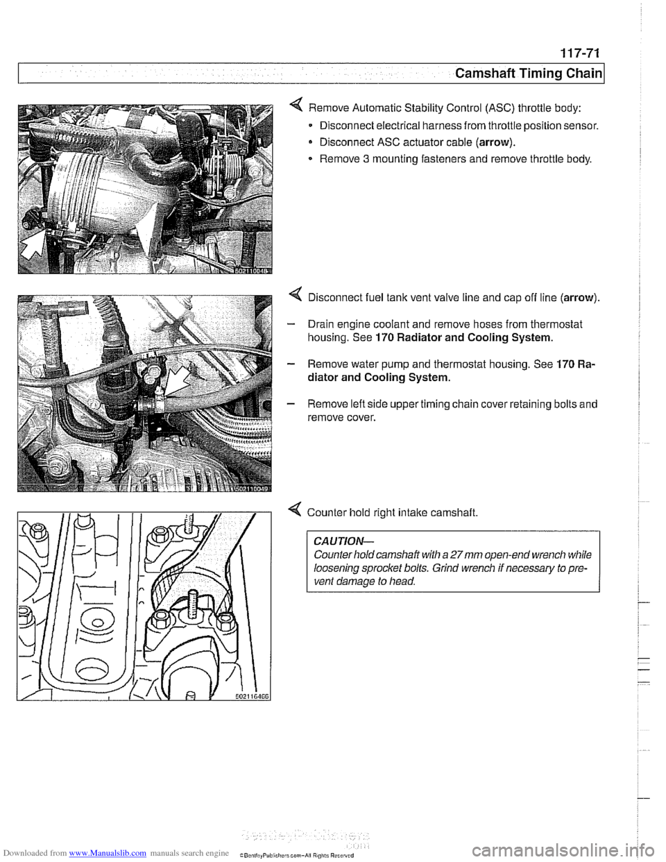
< Remove Automatic Stability Control (ASC) throttle body:
Disconnect electrical harness from throttle position sensor.
Disconnect ASC actuator cable (arrow).
Remove
3 mounting fasteners and remove throttle body.
4 Disconnect fuel tank vent valve line and cap off line (arrow).
- Drain engine coolant and remove hoses from thermostat
housing. See
170 Radiator and Cooling System.
- Remove water pump and thermostat housing. See 170 Ra-
diator and Cooling System.
- Remove left side upper timing chain cover retaining bolts and
remove cover.
4 Counter hold right intake camshaft
CAUTION-
Counter hold camshaft with a 27mm open-end wrench while
loosening sprocket bolts. Grind wrench if necessary to pre-
vent damage to head.
Page 353 of 1002
Downloaded from www.Manualslib.com manuals search engine
Lnition switch
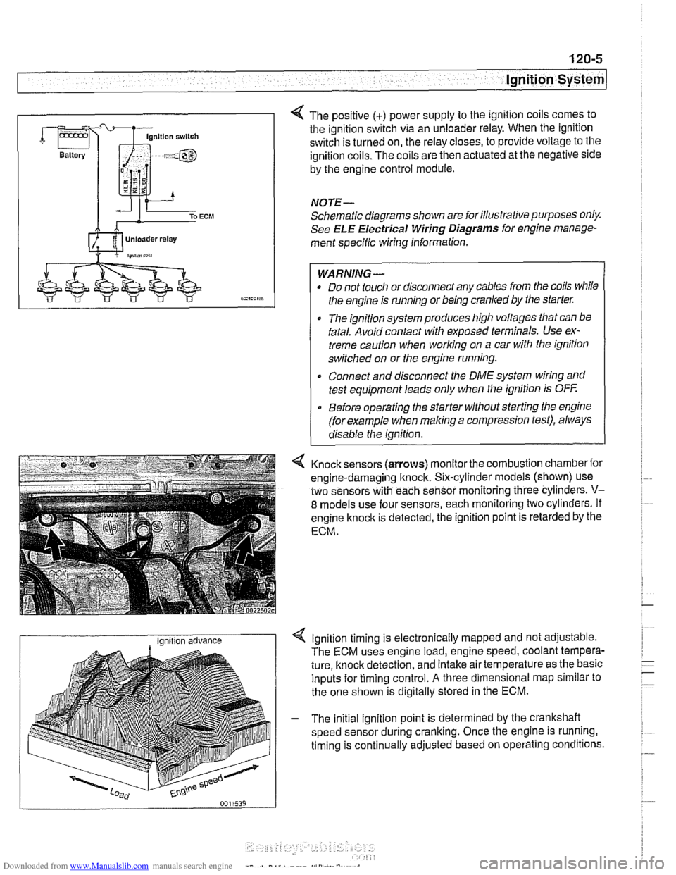
4 The positive (+) power supply to the ignition coils comes to
the ignition switch via an unloader relay. When the ignition
switch is turned on, the relay closes, to provide voltage to the
ignition coils. The coils are then actuated at the negative side
by the engine control module.
NOTE-
Schematic diagrams shown are for illustrative purposes only.
See ELE Electrical Wiring Diagrams for engine manage-
ment specific wiring information.
WARNING- Do not touch or disconnect any cables from the coils while
the engine is running or being cranked by the starter:
The ignition system produces high voltages that can be
fatal. Avoid contact with exposed terminals. Use ex-
treme caution when
working on a car with the ignition
switched on or the engine running.
* Connect and disconnect the DME system wiring and
test equipment leads only when the ignition is
OFF
Before operating the starter without starting the engine
(for example when
making a compression test), always
disable the ignition.
4 Knock sensors (arrows) monitor the combustion chamber for
engine-damaging knock. Six-cylinder models (shown) use
two sensors with each sensor monitoring three cylinders.
V-
8 models use four sensors, each monitoring two cylinders. If
engine
knock is detected, the ignition point is retarded by the
ECM.
I Ignition advance Ignition timing is electronically mapped and not adjustable.
The ECM uses engine load, engine speed, coolant tempera-
ture, knock detection, and intake air temperature as the basic
inputs for timing control.
A three dimensional map similar to
the one shown is digitally stored in the ECM.
- The initial ignition point is determined by the crankshaft
speed sensor during cranking. Once the engine is running.
timing is continually adjusted based on operating conditions.
Page 384 of 1002
Downloaded from www.Manualslib.com manuals search engine
121-18
I Battery, Starter, Alternator
Alternator, removing and installing
(M62 TU engine, water cooled)
V-8 models produced after 9/98 are equipped with a water
cooled alternator.
CAUTION-
Allow engine to cool before removing alternator as coolant
will
escape from the alternator water jacket.
- Disconnect negative (-) battery cable
CAUTION- Prior to disconnecting the
battew read the battery discon-
nection cautions given in
001 General Warnings and Cau-
tions.
- Remove radiator cooling fan and fan shroud. See 170 Radi-
ator and Cooling System.
- Drain engine cooling system. See 170 Radiator and Cool-
ing System.
- Remove alternator drive belt. See 020 Maintenance.
- Disconnect battery lead (terminal 30 or B+) and two-pin har-
ness connector from front of alternator.
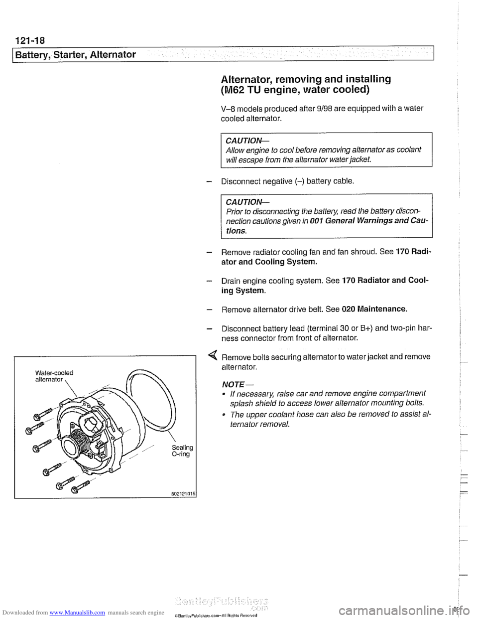
I < Remove bolts securing alternator to water jacket and remove
aling ring
alternator.
NOTE- If necessary, raise car and remove engine compartment
splash shield to access lower alternator mounting bolts.
The upper coolant hose can also
be removed to assist al-
ternator removal.
Page 385 of 1002
Downloaded from www.Manualslib.com manuals search engine
Battery, Starter, Alternator
- Installation is reverse of removal, noting the following:
Replace alternator rubber sealing O-ring.
* Fill and bleed cooling system as described in 170 Radiator
and Cooling System.
Tightening torques
Fan clutch to coolant pump
with
BMW special tool 11 5 040 30 Nm (22 ft-lb)
without
BMW special tool 11 5 040 40 Nm (29 ft-lb)
Terminal 30 (Bc) wire to alternator (ME) 13 Nm (10 ft-lb)
STARTER
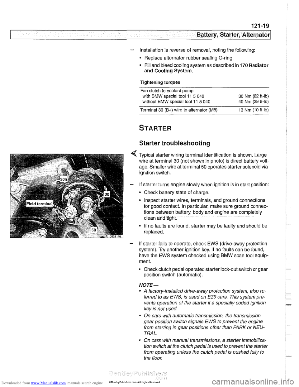
Starter troubleshooting
Typical starter wiring terminal identification is shown. Large
wire at terminal
30 (not shown in photo) is direct battery volt-
age. Smaller wire at terminal
50 operates starter solenoid via
ignition switch.
If starter turns engine slowly when ignition is in start position:
Check battery state of charge.
Inspect starter wires, terminals, and ground
connectlons
for good contact. In particular, make sure ground connec-
tions between battery, body and
englne are completely
clean and tight.
If no faults are found, starter may be faulty and should be
replaced.
- If starter fails to operate, check EWS (drive-away protection
system). Try another ignition key.
If no faults can be found,
have the EWS system checked using
BMW scan tool equip-
ment.
Checkclutch pedal operated
starter lock-out switch or gear
position switch (automatic).
NOTE-
* A factory-installed drive-away protection system, also re-
ferred to as
EWS, is used on E39 cars. This system pre-
vents operation of the starter if a specially coded ignition
key is not used.
On cars with automatic transmission, the transmission
gear position switch signals
EWS to prevent the engine
from starting in gear positions other than PARK or NEU-
TRAL.
On cars with manual transmissions, a starter immobiliza-
tion switch
at the clutch pedal is used to prevent the starter
from operating unless the clutch pedal is pushed fully to
the floor.
Page 391 of 1002
Downloaded from www.Manualslib.com manuals search engine
130-1
130 Fuel injection
General ........................... .I3 0.2
Tools and test equipment .............. .I3 0.3
Warnings and cautions ................ .I3 0.5
Fuel Supply ....................... .I3 0.6
Relieving system fuel pressure .......... .I3 0.6
Siemens MS 41 . 1. ................... 1 30-7
ECM relay. testing .................... .I3 0.7
Mass air flow (MAF) sensor.
checking and replacing
................ .I3 0.9
Engine coolant temperature (ECT) sensor.
testing and replacing
.................. 130-10
Intake air temperature (IAT) sensor.
testing and replacing
................. .I3 0.1 1
Throttle position sensor (TPS).
testing and replacing
.................. 130-1 2
ldle speed control valve.
checking and replacing
............... .I3 0.1 3
Fuel injectors. checking and replacing .... 130-15
Evaporative emissions. overview ....... .I3 0.1 6
Secondary air injection. overview ....... .I3 0-17
Engine control module (ECM).
removing and installing
................ 130-18
Siemens MS 41.1 ECM pin assignments . .I3 0.19
Siemens MS 42.0 and MS 43.0. ..... .I3 0.23
ECM relay. testing ................... .I3 0.27
Mass air flow (MAF) sensor.
checking and replacing
............... .I3 0.28
Engine coolant temperature (ECT) sensor.
testing and replacing
................. .I3 0.30
Intake air temperature (IAT) sensor.
testing and replacing
................. .I3 0.31
MS 42.0 throttle valve assembly. replacing . 130-32
MS 43.0 throttle valve assembly. replacing . 130-35
Throttle cable. adjusting (MS 42.0) ...... .I3 0.38
ldle speed control valve. checking
and replacing
....................... .I3 0.38
Evaporative emissions control diagrams . . 130- 39
Evaporative emissions control.
(MS
42.0 and MS 43.0). .............. .I3 0.39
Engine control module (ECM).
removing and installing
................ 130-40
Siemens MS 42.0 and MS 43.0
ECM pin assignments ................. 130-41
Bosch M5.2 (M62 up to 911997)
BOSC~ M5.2.1 (M62 911997 to 911998) 130-46
M5.2 system features ................. 130-47
M5.2.1 system features ............... 130-47
ECM relay. testing ................... 130-49
Oxygen sensors. checking ............. 130-51
Fuel injectors. checking and replacing .... 130-52
Mass air flow (MAF) sensor. replacing .... 130-53
ldle speed control valve. testing
and replacing
....................... 130-54
Throttle position sensor (TPS).
testing and replacing
................. 130-55
Engine coolant temperature (ECT) sensor.
testing and replacing
................. 130-55
Intake air temperature (IAT) sensor.
testing and replacing
................. 130-57
Auxiliary throttle valve (ADS) (M62 and
M62 TU engine). replacing ..... 130-57
Evaporative system pressure
leak diagnosis. overview
(5.2.1 only) ..... 130-58
Bosch 5.2 ECM pin assignments
(M62 UP to 911 997) ................... 130-59
~osch 5.2.1 ECM pin assignments
(M62 911 997 to 911 998) ............... 130-62
BOSC~ ME 7.2 ..................... 1 30-66
ME 7.2 system overview ............... 130-67
EDK adaptation ..................... 130-69
ECM relay. checking .................. 130-69
Engine coolant temperature
(ECT) sensor. testing
................. 130-71
Engine coolant temperature
(ECT) sensor. replacing
............... 130-71
Oxygen sensors. replacing ............. 130-72
Fuel injectors. removing and installing .... 130-72
Mass air flow (MAF) sensor.
removing and installing
................ 130-73
Evaporative system pressure
leak diagnosis. overview
............... 130-74
Secondary air injection. overview ........ 130-75
Bosch ME 7.2 ECM pin assignments .... 130-76