light BMW 540i 2000 E39 Manual Online
[x] Cancel search | Manufacturer: BMW, Model Year: 2000, Model line: 540i, Model: BMW 540i 2000 E39Pages: 1002
Page 562 of 1002
Downloaded from www.Manualslib.com manuals search engine
1 Clutch
- lnstall flywheel lock, special tool 11 2 170 (6 cylinder model)
or
11 2 070 (V-8 model).
- lnstall SAC pressure plate on dowel pins at flywheel. lnstall
clutch mounting bolts and tighten each one turn at a time until
pressure plate is fully seated. Torque to specification.
Tightening torques
Clutch to flywheel
- M8 (8.8 grade)
M8 (10.9 grade) 24
Nm (18
ft-ib)
34
Nm (25 ft-lb)
- Slip out clutch centering tool using large bolt.
- Remove flywheel locking tool.
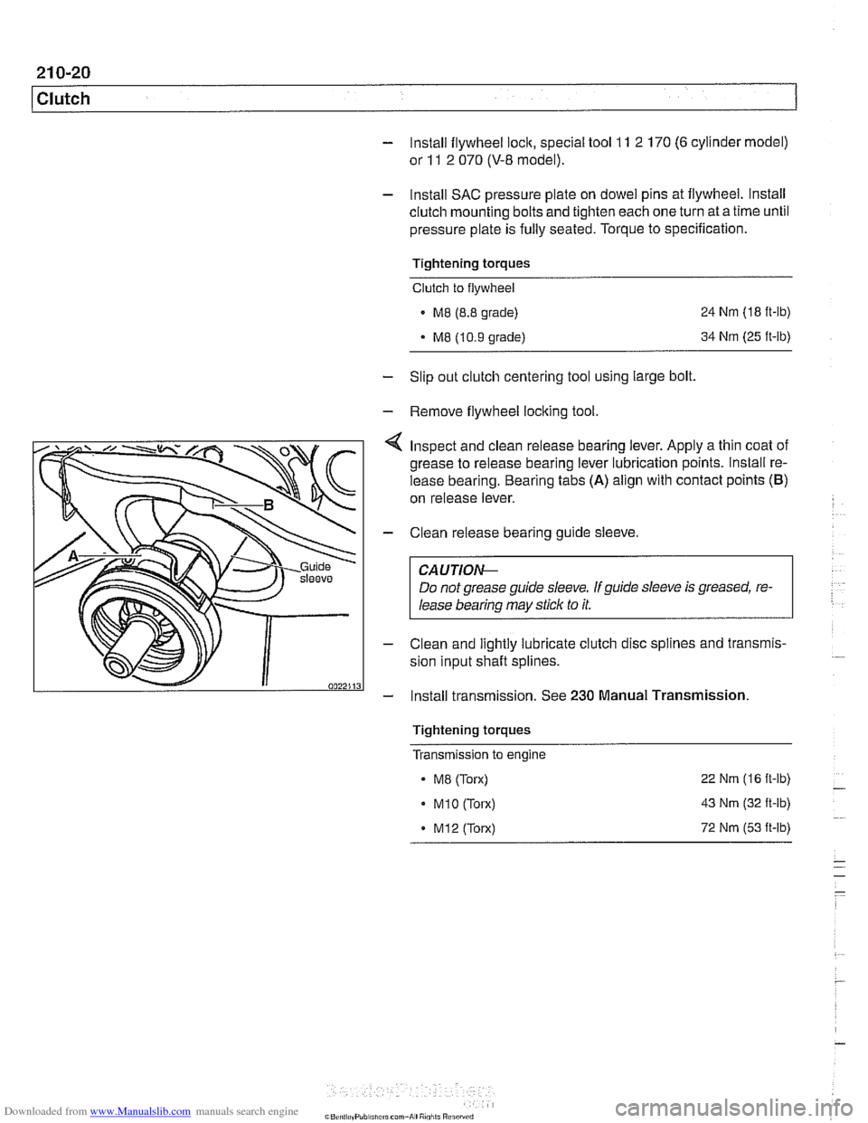
Inspect and clean release bearing lever. Apply a thin coat of
grease to release bearing lever lubrication points. lnstall re-
lease bearing. Bearing tabs
(A) align with contact points (B)
on release lever.
- Clean release bearing guide sleeve.
CA U TIOG
Do not grease guide sleeve. If guide sleeve is greased, re-
lease bearing may stick to it.
- Clean and lightly lubricate clutch disc splines and transmis-
sion input shaft splines.
- Install transmission. See 230 Manual Transmission
Tightening torques
Transmission to engine
- ME (Torx)
. M1O (Torx)
. M12 (Torx) 22
Nm (16 ft-lb)
43
Nm (32 ft-lb)
72
Nm (53 it-lb)
Page 563 of 1002
Downloaded from www.Manualslib.com manuals search engine
Self-adjusting clutch (SAC), breaking in
With normal driving, 800 to 1000 gearshifts are required to
break in the clutch.
Break in the SAC gradually, with light to medium loads, to en-
sure correct operation and long life. Fast sports driving ma-
neuvers may destroy a new
clutch.The following break-in
procedure helps to create the correct coefficient of friction.
Drive normally on level grade. Starting speeds on level
grade may be up to 2000 rpm.
Upshift and downshift through all the gears at 3500
- 4000
rpm.
On medium grades (approx. 12% and up), start
off at ap-
prox. 2500 rpm for the first 5 or so times.
Tightening torques
Clutch slave cylinder to transmission case 22 Nm (16 It-lb)
Clutch master cylinder to pedal cluster 10 Nm (89 in-lb)
Bralte fluid line to clutch master or slave cylinder 17 Nm (13 ft-lb)
Transmission to engine
M8 (Torx) 22 Nm (16 fl-lb)
. M1O (Torx) 43 Nm (32 ft-lb)
MI2 (Torx) 72 Nm (53 it-lb)
Flywheel to crankshaft
6 cylinder engine (use new self-loclting bolts) 105 Nm (77 ft-lb)
V-8 engine 105 Nm (77 ft-lb)
Clutch to flywheel
M8 (8.8 grade)
M8 (10.9 grade) 24
Nm
(18 ft-lb)
34 Nm (25 ft-lb)
Page 565 of 1002
Downloaded from www.Manualslib.com manuals search engine
230 Manual Transmission
General ........................... .23 0.2 Output shaft
seal. replacing (5-speed
.... Special tools ........................ .23 0.2 transmission) (transmission installed) 230-10
Manual transmission aoolications ....... .23 0.5 Output shaft seal. replacing (6-speed . . .... transmission) (transmission installed) 230-12 ........ Transmission Fluid Service .23 0.6 put shaft seal. replacing
Transmission fluid level. checking ....... .23 0.6 (transmission ............... 230-15
........... Transmission fluid, replacing .23 0.6
Transmission Removal ................... ..... Transmission External Service .23 0-7 and installation 230-1
Back-up light switch, replacing .......... .23 0-' Transmission, removing and installing 230-16 ...
Selector shaft seal. reolacina .
(transmission installed) ................ .23 0.8
Page 571 of 1002
Downloaded from www.Manualslib.com manuals search engine
230-7
Manual Transmission
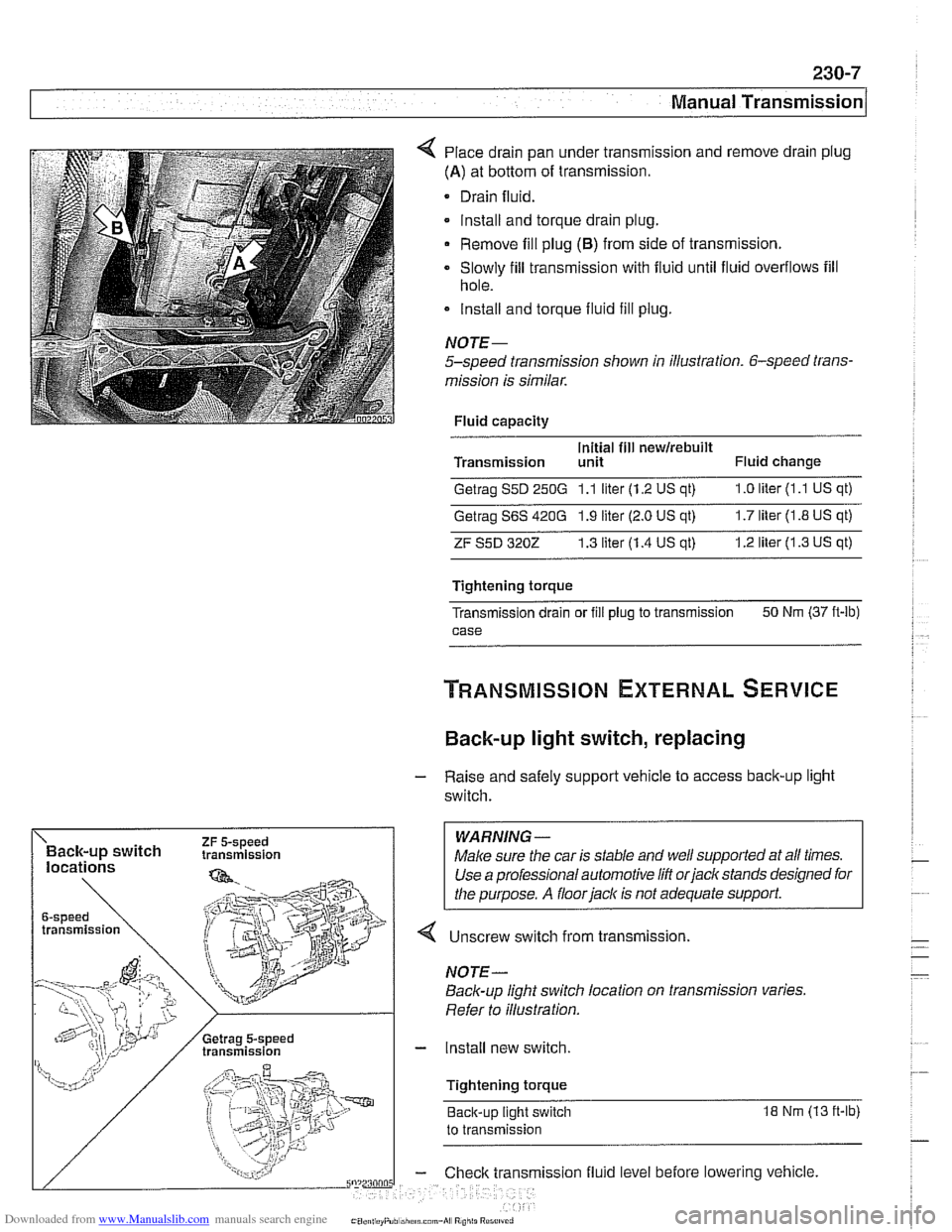
Place drain pan under transmission and remove drain plug
(A) at bottom of transmission.
Drain fluid.
lnstall and torque drain plug.
Remove fill plug
(6) from side of transmission.
Slowly fill transmission with fluid until fluid overflows fill
hole.
lnstall and torque fluid fill
plug.
NOJE-
5-speed transmission shown in illustration. 6-speed trans-
mission is similar.
Fluid capacity
Initial fill
newirebuilt Transmission unit Fluid change
Getrag S5D 250G 1.1 liter (1.2 US qt) 1.0 liter (1 .l US qt)
Getrag S6S 420G 1.9 liter (2.0 US qt) 1.7 liter (1.8 US qt)
ZF S5D 3202 1.3 liter (1.4 US at) 1.2 liter (1.3 US qt)
Tightening torque
Transmission drain or
fill plug to transmission 50
Nm (37 ft-lb)
case
Back-up light switch, replacing
- Raise and safely support vehicle to access back-up light
switch.
WARNING -
4 Unscrew switch from transmission.
Back-up light switch location on transmission varies.
Refer to illustration.
- Install new switch.
Tightening torque Back-up light switch
18 Nm (13 ft-lb)
to transmission
ission fluid level before lowering vehicle.
Page 581 of 1002
Downloaded from www.Manualslib.com manuals search engine
--.
- - Manual Transmission
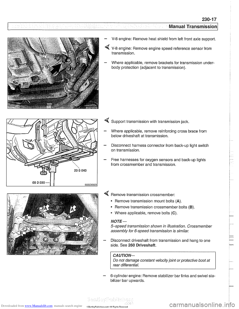
- V-8 engine: Remove heat shield from left front axle support.
< V-8 engine: Remove engine speed reference sensor from
transmission.
- Where applicable, remove brackets for transmission under-
body protection (adjacent to transmission).
4 Support transmission with transmission jack.
- Where applicable, remove reinforcing cross brace from
below driveshaft at transmission.
- Disconnect harness connector from back-up light switch
on transmission.
- Free harnesses for oxygen sensors and back-up lights
from crossmember and transmission.
Remove transmission crossmember: Remove transmission mount bolts
(A).
Remove transmission crossmember bolts (B)
Where applicable, remove bolts (C).
NOTE-
5-speed transmission shown in illustration. Crossmember
assembly for 6-speed transmission is similar.
Disconnect driveshaft from transmission and hang to one
side. See
260 Driveshaft.
I CAUTION- I
Do not damage constant velocity joint orprotective boot at
rear differential.
- 6-cylinder engine: Remove stabilizer bar links and swivel sta-
bilizer bar
u~wards.
Page 583 of 1002
Downloaded from www.Manualslib.com manuals search engine
Manual Transmission
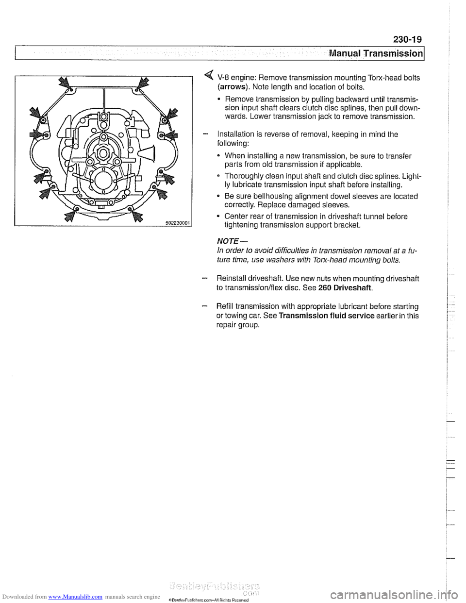
4 V-8 engine: Remove transmission mounting Tom-head bolts
(arrows). Note length and location of bolts.
Remove transmission by pulling backward until transmis-
sion input shaft clears clutch disc splines, then pull down-
wards. Lower transmission jack to remove transmission.
- Installation is reverse of removal, keeping in mind the
following:
When installing a new transmission, be sure to transfer
parts from old transmission
if applicable.
Thoroughly clean input shafl and clutch disc splines. Light-
ly lubricate transmission input shaft before installing.
* Be sure bellhousing alignment dowel sleeves are located
correctly. Replace damaged sleeves.
Center rear of transmission in driveshaft tunnel before
tightening transmission support bracket.
NOTE-
In order to avoid difficulties in transmission removal at a fu-
ture time, use washers with Torx-head mounting bolts.
- Reinstall driveshaft. Use new nuts when mounting driveshaff
to transmission/flex disc. See 260 Driveshaft.
- Refill transmission with appropriate lubricant before starting
or towing car. See Transmission fluid service earlier in this
repair group.
Page 616 of 1002
Downloaded from www.Manualslib.com manuals search engine
260-1 0
/ Driveshaft
Driveshaft, installing
- Prepare CV joint for reinstallation:
Extend joint to limit.
Clean off old grease and fill with fresh grease
Install new seal.
- Bend driveshaft slightly at center universal joint to install
CAUTION-
Do not allow CVjoint seal to become displaced.
- Align matchmarlts on driveshaft to matchmarks on final drive
and transmission flanges.
- Fit constant velocity joint to final drive input flange. Alternate-
ly tighten two opposite nuts to draw constant velocity joint
evenly into the final drive input flange. Once seated, tighten
down remaining nuts.
I CAUTION-
I Do not reuse self-locking nuts. These nuts are designed to be /
I used onlv once. 1
- Insert bolts in front of driveshafl to transmission output
flange. Counterhold each bolt while tightening nut.
CAUTION-
. Do not reuse self-locking nuts. These nuts are designed to
be used only once.
Avoid stressing the flex-disc when torquing the bolts.
Do this by counterholding the bolts and turning the nuts
on the flange side.
- Position center support bearing and install mounting nuts.
Use new self-locking nuts.
- Install heat shields.
- Install rear transmission support crossmember.
- Install exhaust system. See 180 Exhaust System.
Reconnect oxygen sensor wiring harnesses and reattach
wiring harness retainers to rear transmission support
crossrnernber.
Page 617 of 1002
Downloaded from www.Manualslib.com manuals search engine
Driveshaft
- Road test vehicle to check for noise or vibration
CAUTION-
Do not reuse self-locking nuts. These nuts are designed to
be used only once.
Avoid stressing the flex-disc when torquing the bolts.
Do this by counterholding the bolts and turning the nuts
on the flange side.
Tightening torques
Alunlinum driveshaft to flex-disc
- MI2 (use coated washers)
90 Nm (66 ft-lb)
Driveshaft
CV joint to final drive flange
Mi0 (Tom bolt)
70 Nm (51 ft-lb)
M8 (compression nut) 32 Nm (24 ft-lb)
Flex-disc to transmission flange or driveshaft
MI0 (8.8 grade) 48 Nm (35 ft-lb)
MI 0 (1 0.9 grade) 60 Nm (44 ft-lb)
- Mi2 (8.8 grade)
81 Nm (60 ft-lb)
- MI2 (10.9 grade) I00 Nm (74 ft-lb)
MI4 140 Nm (103 ft-lb)
Transmission
crossmember
to transmission (ME) 21 Nm (15 ft-lb)
. to chassis (M10) 42 Nm (30 ft-lb)
NOTE-
Boltgrade is marked on the bolt head. When replacing bolts,
only use bolts of the same strength and hardness as the orig-
inals installed.
Flex-disc, replacing
- Checlc flex-disc between front section of driveshafl and trans-
mission output flange for craclts, tears, missing pieces, or
distortion. Check for worn bolt hole bores in flange.
- If flex-disc needs replacement, remove driveshafl as de-
scribed earlier.
- Unbolt flex-disc from driveshaft.
NOTE-
Removal andinstallation of the bolts may be made easier by
placing a large hose clamp around the flex-disc, and tighten-
ing the clamp slightly to compress the rubber.
Page 630 of 1002
Downloaded from www.Manualslib.com manuals search engine
300-1 0
/Suspension, Steering and Brakes - General
The steering system features variable power assist provided
by an engine-driven hydraulic pump.
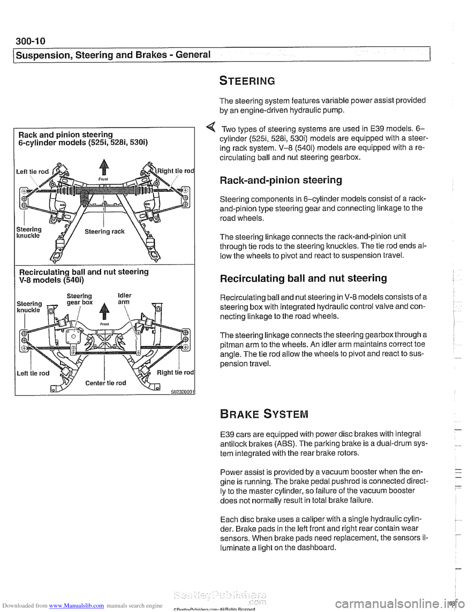
Rack and pinion steering
6-cylinder models
(525i, 5281, 5300
Two types of steering systems are used in E39 models. 6-
cylinder (525i, 5281, 530i) models are equipped with a steer-
ing rack system. V-8
(540i) models are equipped with a re-
circulating ball and nut steering gearbox.
Rack-and-pinion steering
Steering components in 6-cylinder models consist of a rack-
and-pinion type steering gear and connecting linltage to the
road wheels.
The steering linkage connects the rack-and-pinion unit
through tie rods to the steering knucltles. The tie rod ends al-
low the wheels to pivot and react to suspension travel.
Recirculating ball and nut steering
V-8 models
(540i)
I
Recirculating ball and nut steering
Recirculating ball and nut steering in V-8 models consists of a
steering box with integrated hydraulic control valve and con-
necting linkage to the road wheels.
Thesteering linkageconnects the steering gearbox through a
pitman arm to the wheels. An idler arm maintains correct toe
angle. The tie rod allow the wheels to pivot and react to sus-
pension travel.
E39 cars are equipped with power disc brakes with integral
antilock brakes (ABS). The parking bralte is a dual-drum sys-
tem integrated with the rear brake rotors.
Power assist is provided by a vacuum booster when the en-
gine is running. The brake pedal
pushrod is connected direct-
ly to the master cylinder, so failure of the vacuum booster
does not normally result in total
bralte failure.
Each disc bralte uses a caliper with a single hydraulic cylin-
der. Brake pads in the left front and right rear contain wear
sensors. When brake pads need replacement, the sensors il-
luminate a light on the dashboard.
Page 641 of 1002
Downloaded from www.Manualslib.com manuals search engine
31 0-5
Front ~uspensionl
Front strut assembly, removing and
installing
- Raise car and remove front wheel.
WARNING-
Make sure that the car is firmly supported on jack stands de-
signed for the purpose. Place jack stands underneath struc-
tural chassis points.
Do not place jack stands under
suspension
parts.
- Unbolt bralte caliper assembly, lkeeping bralte hose connect-
ed. Secure brake caliper to body with wire. Do not let it hang
from brake hose. See
340 Brakes.
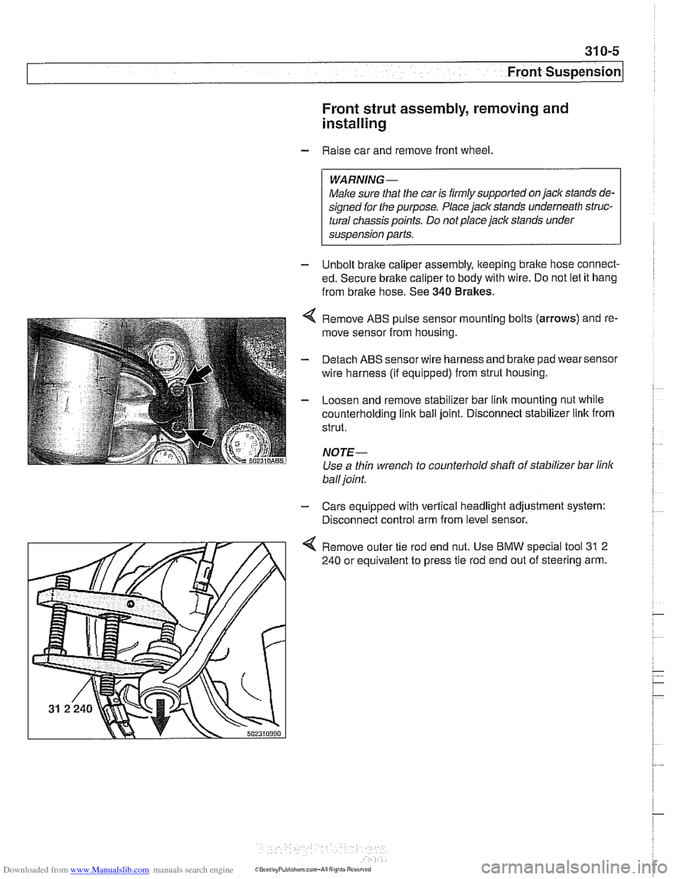
Remove ABS pulse sensor mounting bolts (arrows) and re-
move sensor from housing.
Detach ABS sensor wire harness and bralte pad wear sensor
wire harness (if equipped) from strut housing.
Loosen and remove stabilizer bar link mounting nut while
counterholding
link ball joint. Disconnect stabilizer link from
strut.
NOTE-
Use a thin wrench to counterhold shaft of stabilizer bar link
ball joint.
- Cars equipped with vertical headlight adjustment system:
Disconnect control arm from level sensor.
4 Remove outer tie rod end nut. Use BMW special tool 31 2
240 or equivalent to press tie rod end out of steering arm.