oil pan drain plug BMW 540i 2000 E39 Workshop Manual
[x] Cancel search | Manufacturer: BMW, Model Year: 2000, Model line: 540i, Model: BMW 540i 2000 E39Pages: 1002
Page 26 of 1002
Downloaded from www.Manualslib.com manuals search engine
.-
General
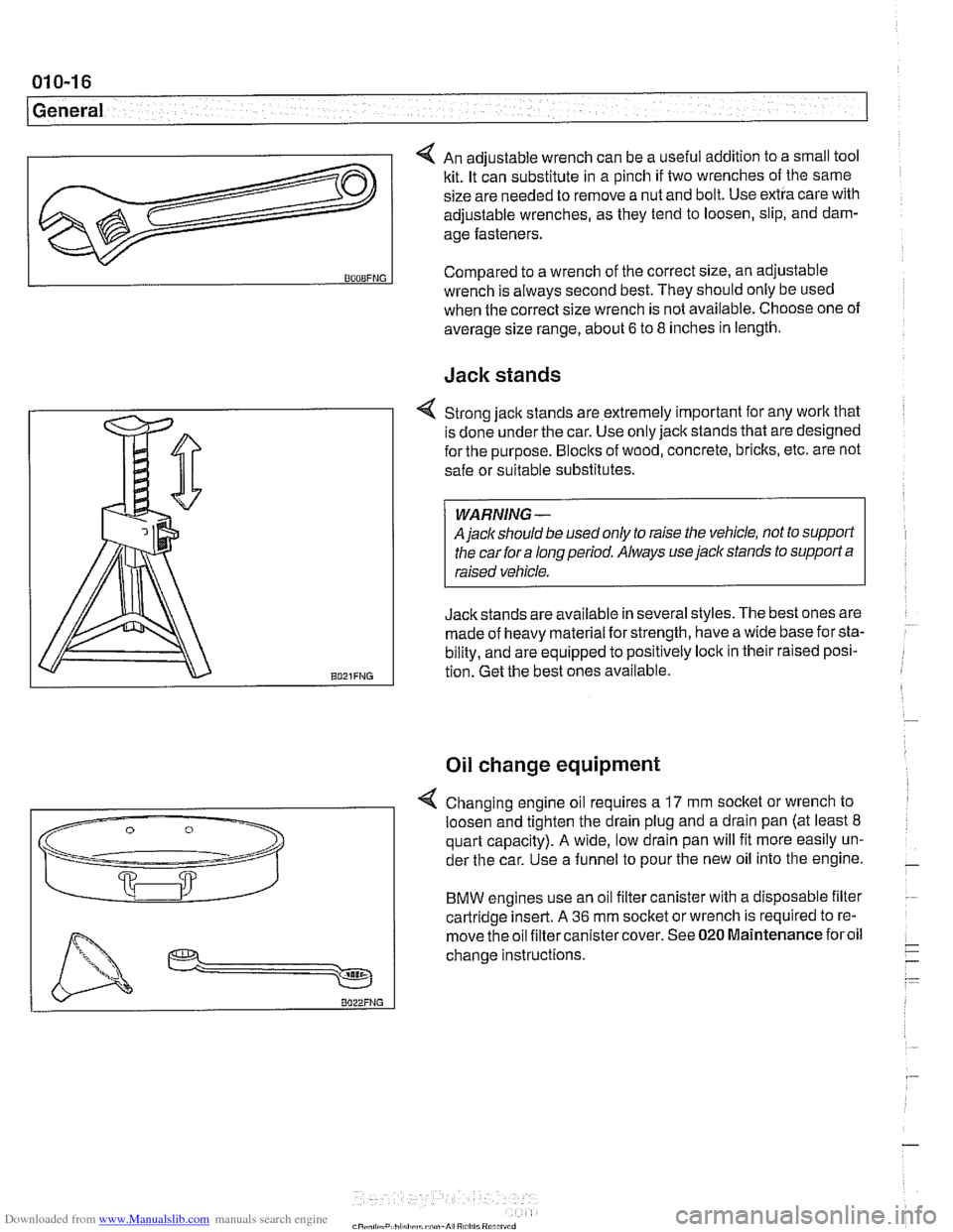
4 An adjustable wrench can be a useful addition to a small tool
kit. It can substitute in a pinch if two wrenches of the same
size are needed to remove a nut and bolt. Use extra care with
adjustable wrenches, as they tend to loosen, slip, and dam-
age fasteners.
Jack stands
v
BOOBFNG
4 Strong jack stands are extremely important for any work that
is done under the car. Use only jack stands that are designed
for the purpose.
Blocks of wood, concrete, bricks, etc. are not
safe or suitable substitutes.
A
jaclc should be used only to raise the vehicle, not to support
the car for a long period. Always use
jack stands to support a
Jackstands are available in several styles. The best ones are
:
made of heavy material for strength, have a wide base for sta-
bility, and are equipped to positively lock in their raised posi-
tion. Get the best ones available.
Compared to
a wrench of the correct size, an adjustable
Oil change equipment
wrench is always second best. They should only be used
when the correct size wrench is not available. Choose one of
average size range, about
6 to 8 inches in length.
4 Changing engine oil requires a 17 mm socket or wrench to
loosen and tighten the drain plug and a drain pan (at least
8
quart capacity). A wide, low drain pan will fit more easily un-
der the car. Use a funnel to pour the new oil into the engine.
BMW engines use an oil filter canister with a disposable filter
cartridge insert. A
36 mm socket or wrench is required to re-
move the oil filtercanistercover. See
020 Maintenance foroil
change instructions.
Page 45 of 1002
Downloaded from www.Manualslib.com manuals search engine
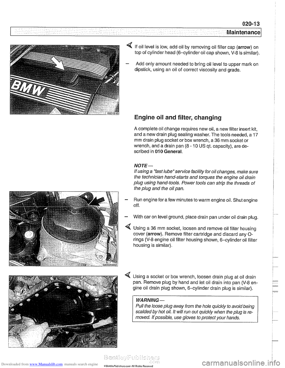
4 If oil level is low, add oil by removing oil filler cap (arrow) on
top of cylinder head
(6-cylinder oil cap shown, V-8 is sirnilar).
- Add only amount needed to bring oil level to upper mark on
dipstick, using an oil of correct viscosity and grade.
Engine oil and filter, changing
A complete oil change requires new oil, a new filter insert kit,
and a new drain plug sealing washer. The tools needed, a
17
mm drain plug socket or box wrench, a 36 mm socket or
wrench, and a drain pan (8
- 10 US qt. capacity), are de-
scribed in
010 General.
NOTE-
If using a "fast 1ube"service facility for oil changes, make sure
the technician hand-starts and torques the engine oil drain
plug using hand-tools. Power tools can strip the threads of
the plug and the oil pan.
Run engine for afew minutes to warm engine oil. Shut engine
off.
With car on level ground, place drain pan under oil drain plug.
Using a
36 mm socket, loosen and remove oil filter housing
cover (arrow). Remove filter cartridge and discard any
0-
rings (V-8 engine oil filter housing shown, 6-cylinder oil filter
housing is sirnilar).
Using a socket or box wrench, loosen drain plug at oil drain
pan. Remove plug by hand and let oil drain into pan
(V-8 en-
gine oil drain plug shown, 6-cylinder drain plug is similar).
WARNING -
Pull the loose plug away from the hole quicldy to avoid being
scalded by hot oil. It will run out
quiclcly when the plug is re-
Page 46 of 1002
Downloaded from www.Manualslib.com manuals search engine
020-1 4
Maintenance
- When oil flow has diminished to an occasional drip, reinstall
drain plug with a new metal sealing washer and torque plug.
Tightening torque Engine oil drain plug to oil pan
25 Nrn (1.8 ft-lb)
6-cylinder oil filter assembly
r------ 1
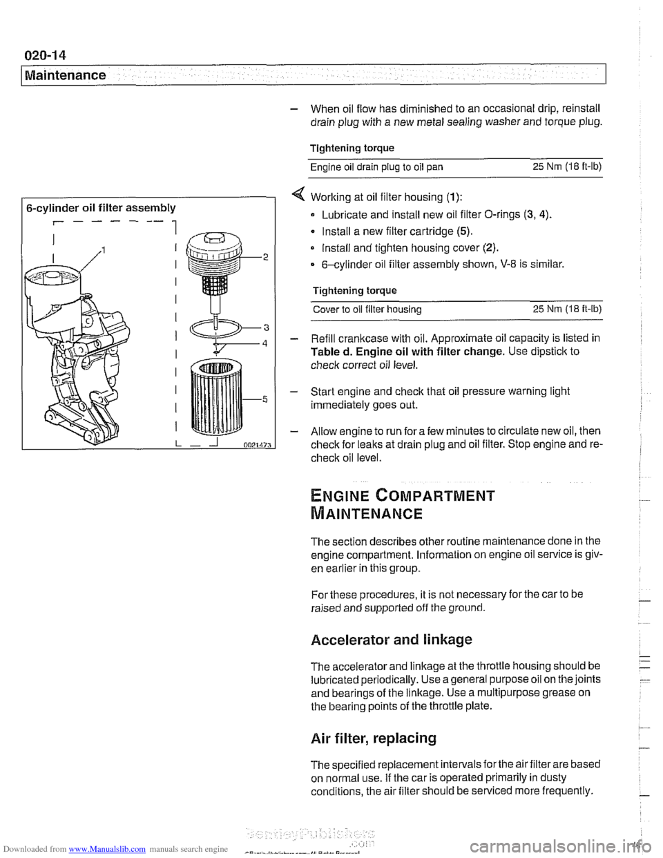
< Working at oil filter housing (1):
Lubricate and install new oil filter O-rings (3, 4).
Install a new filter cartridge (5).
lnstall and tighten housing cover (2).
6-cylinder oil filter assembly shown, V-8 is similar.
Tightening torque Cover to oil filter housing
25 Nm (1.8 it-lb)
- Refill crankcase with oil. Approximate oil capacity is listed in
Tabled. Engine oil with filter change. Use dipstick to
check correct oil level.
- Start engine and check that oil pressure warning light
immediately goes out.
- Allow engine to run fora few minutes to circulate new oil, then
check for leaks at drain plug and oil filter. Stop engine and re-
check oil level
The section describes other routine maintenance done in the
engine compartment. Information on engine oil service is
giv-
enkar~ier inthis group.
For these procedures, it is not necessary for the car to be
raised and supported off the ground.
Accelerator and linkage
The accelerator and linkage at the throttle housing should be
lubricated periodically. Use ageneral purposeoil on the joints
and bearings of the linkage. Use a multipurpose grease on
the bearing points of the throttle plate.
Air filter, replacing
The specified replacement intervals forthe air filter are based
on normal use. If the car is operated primarily in dusty
conditions, the air filter should be serviced more frequently.
Page 287 of 1002
Downloaded from www.Manualslib.com manuals search engine
... -.
Camshaft Timing chain1
Timing chains, removing
(M52 TU and M54 engines)
Camshaft timing chain removal requires that the oil pan be re-
moved. See
119 Lubrication System. Also required is re-
moval of the VANOS control
unit and disassembly of the
intake and exhaust camshaft sprocket assemblies as de-
scribed earlier in this repair group.
Special BMW
service tools are needed for timing chain re-
moval and installation. The special tools assure proper timing
of the valvetrain. Precise
marlts to set the timing on the cam:
shafts are not provided for reassembly. Read the procedures
through before beginning the job.
CA
UTION-
If the camshafts are not properly timed, the pistons can con-
tact the valves.
- D~sconnect negative (-) cable from battery.
CAUTION-
* Disconnecting the battery may erase fault code@) stored in
control module memory. Check for fault codes using spe-
cial
BMW diagnostic equipment.
Prior to disconnecting the battery, read the battery dis-
connection
cautfons given in 001 General Cautions
and
Warninqs.
- Remove VANOS control unit. See VANOS control unit, re-
moving
(M52 TU and M54 engines).
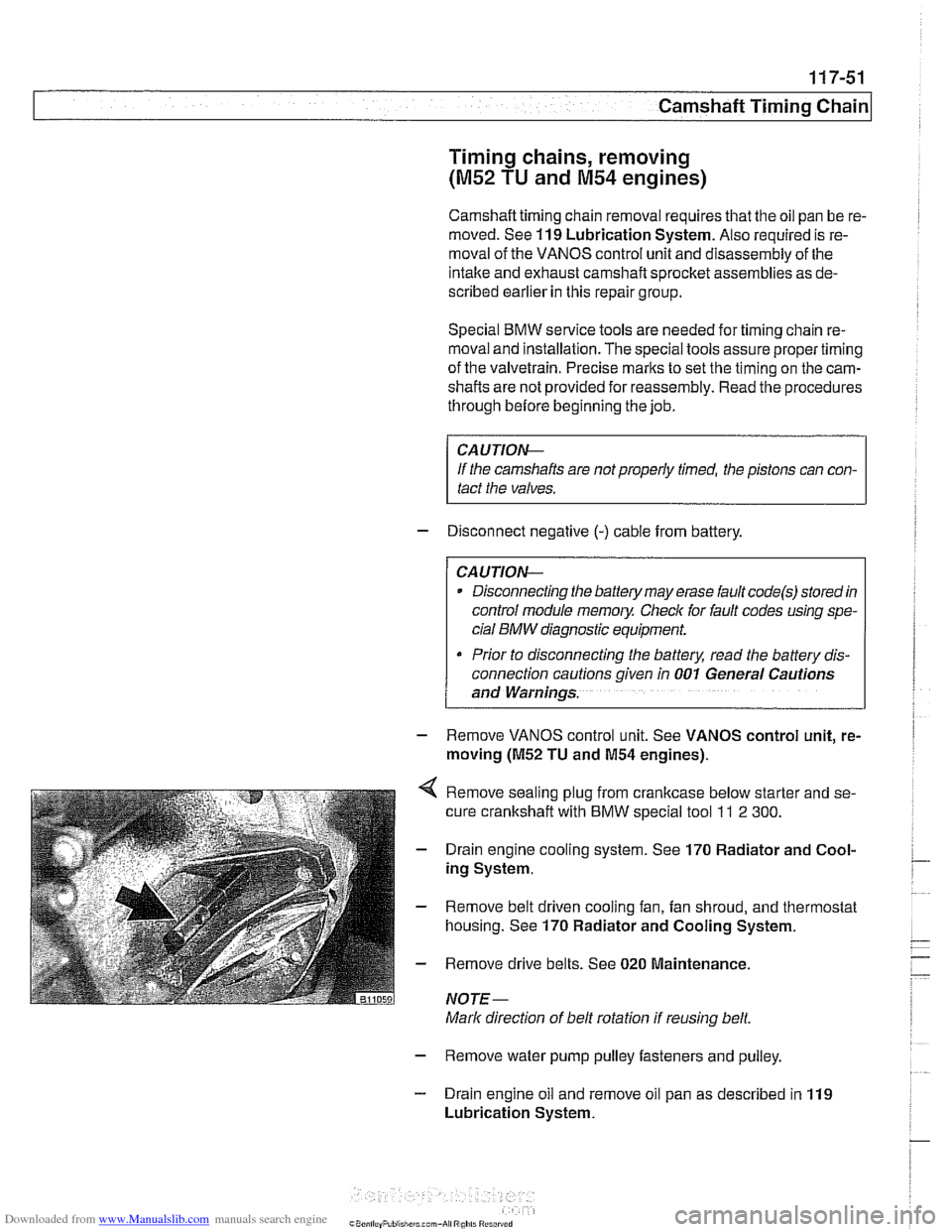
Remove sealing plug from crankcase below starter and se-
cure crankshaft with
BMW special tool ll 2 300.
Drain engine cooling system. See 170 Radiator and Cool-
ing System.
Remove belt driven cooling fan, fan shroud, and thermostat
housing. See
170 Radiator and Cooling System.
Remove drive belts. See
020 Maintenance.
NOTE-
Mark direction of belt rotation if reusing belt.
- Remove water pump pulley fasteners and pulley.
- Drain engine oil and remove oil pan as described in 119
Lubrication System.
Page 302 of 1002
Downloaded from www.Manualslib.com manuals search engine
11 7-66
I Camshaft Timing Chain
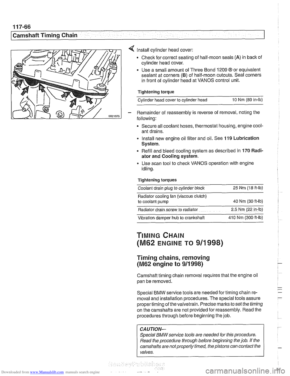
4 install cylinder head cover:
Check for correct seating of half-moon seals
(A) in back of
cylinder head cover.
Use a small amount of Three Bond
1209 8 or equivalent
sealant at corners
(B) of half-moon cutouts. Seal corners
in front of cylinder head at VANOS control unit.
Tightening torque
Cylinder head cover to cylinder head
10 Nm (89 in-lb)
- Remainder of reassembly is reverse of removal, noting the
following:
Secure all coolant hoses, thermostat housing, engine cool-
ant drains.
Install new engine oil filter and oil. See
119 Lubrication
System.
Refill and bleed cooling system as described in
170 Radi-
ator and Cooling system.
Use scan tool to check VANOS operation with engine
idling.
Tightening torques Coolant drain plug to cylinder block
25 Nm (18 ft-lb)
Radiator cooling fan (viscous clutch)
to coolant pump
40 Nm (30 ft-lb)
Radiator drain screw to radrator 2.5 Nm (22 in-lb)
Vibration damper hub to crankshaft 41 0 Nm
(300 ft-ib)
TIMING CHAIN
(M62 ENGINE TO 911998)
Timing chains, removing
(M62 engine to 911 998)
Camshaft timing chain removal requires that the engine oil
pan be removed.
Special
BMW service tools are needed for timing chain re-
moval and installation procedures. The special tools assure
propertiming of thevaivetrain. Precise marks to set the timing
on the camshafts are not provided for reassembly. Read the
procedures through before beginning the job.
CAUTION-
Special BMW service tools are needed for this procedure.
Read the procedure through before beginning the job. If the
camshafts are notproperly timed, the pistons can contact the
valves.
Page 328 of 1002
Downloaded from www.Manualslib.com manuals search engine
I Lubrication System -
- Remainder of assembly is reverse of disassembly.
Install flywheel, clutch or torque converter and
transmission.
Fill engine with oil.
- Run engine and check for leaks.
Tightening torques
Oil
drain plug fo oil pan (MI21 25 Nm (18 ft-lb)
Oil pan to engine
block
M6 (8.8 grade) 10 Nm (89 in-ib)
M6 (1 0.9 grade) 12 Nm (9 ft-lb)
M8 (8.8 grade) 22 Nm (1 6 it-lb)
Rear main seal carrier to crankcase
M6 10 Nm (89 in-lb)
ME 22 Nm (16 ft-lb)
Crankshaft rear main seal, replacing (V-8)
- Remove transmission. See 230 Manual Transmission or
240 Automatic Transmission.
- Manual transmission vehicles: Remove clutch pressure plate
and disc. See
210 Clutch.
- Remove flywheel. See 210 Clutch.
- Drain engine oil.
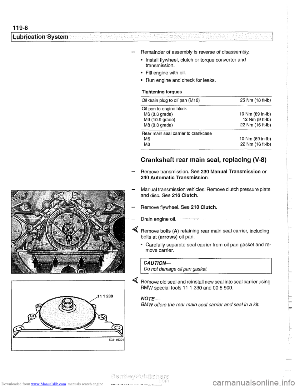
4 Remove bolts (A) retaining rear main seal carrier, including
bolts at (arrows) oil pan.
Carefully separate seal carrier from oil pan gasket and re-
move carrier.
CAUTION-
Do not damage oil pan gasket.
< Remove old seal and reinstall new seal into seal carrier using
) BMW special tools 11 1 230 and 00 5 500.
Page 332 of 1002
Downloaded from www.Manualslib.com manuals search engine
119-12
Lubrication System 1
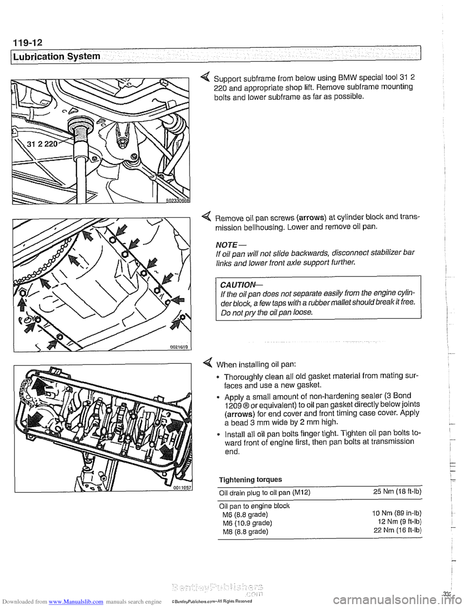
4 Support subframe from below using BMW special tool 31 2
220 and appropriate shop lift. Remove
subframe mounting
bolts and lower
subframe as far as possible.
Remove oil pan screws (arrows) at cylinder block and trans-
mission bellhousing. Lower and remove oil pan.
NOTE-
If oil pan will not slide backwards, disconnect stabilizer bar
links and lower front axle support further.
If the oil pan does not separate easily from the engine cylin-
der
block, a few taps with a rubber malletshould breakit free.
Do not
pry the oil pan loose.
When installing oil pan: Thoroughly clean all old gasket material from mating sur-
faces and use a new gasket.
Apply a small amount of non-hardening sealer
(3 Bond
12098 or equivalent) to oil pan gasket directly below joints
(arrows) for end cover and front timing case cover. Apply
a bead
3 mm wide by 2 mm high.
Install all oil pan bolts finger tight. Tighten oil pan bolts to-
ward front of engine first, then pan bolts at transmission
end.
Tightening
torques
Oil drain plug to oil pan (M12) 25 Nm (18 ft-lb)
Oil pan to engine block
MG (8.8 grade)
MG (10.9 grade)
M8 (8.8 grade)
10 Nm (89 In-lb)
12 Nm (9 ft-lb)
22 Nrn (16 R-lb)
Page 334 of 1002
Downloaded from www.Manualslib.com manuals search engine
.
[Lubrication System
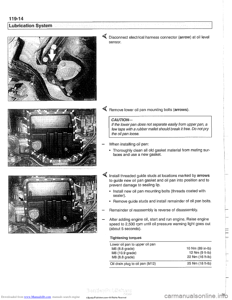
< Disconnect electrical harness connector (arrow) at oil level
sensor.
< Remove lower oil pan mounting bolts (arrows)
CAUTIOI\C
If the lowerpan does not separate easily from upperpan, a
few taps with a rubber mallet should break it free. Do
notpry
the oil pan loose.
- When installing oil pan:
Thoroughly clean all old
gasltet material from mating sur-
faces and use a new gasket.
4 Install threaded guide studs at locations marked by arrows
to guide new oil pan
gasltet and oil pan into position and to
prevent damage to sealing lip.
- Install new oil pan mounting bolts (threads coated with
sealer).
Remove guide studs and install remainder of oil pan bolts.
- Remainder of reassembly is reverse of disassembly
- After adding engine oil, start and run engine. Raise engine
speed to 2,500 rpm until oil pressure warning light goes out
(about 5 seconds).
Tightening torques Lower oil pan to upper
oil pan
M6 (8.8 grade) 10 Nm (89 in-lb)
M6 (10.9 grade) 12 Nm (9 ft-lb)
M8 (8.8 grade) 22 Nm (16 ft-lb)
Oil drain plug to oil pan (M12) 25 Nm (18 ft-lb)
Page 343 of 1002
Downloaded from www.Manualslib.com manuals search engine
Lubrication System
- Lower front suspension and remove oil pan, as described
earlier, to gain access to oil pump.
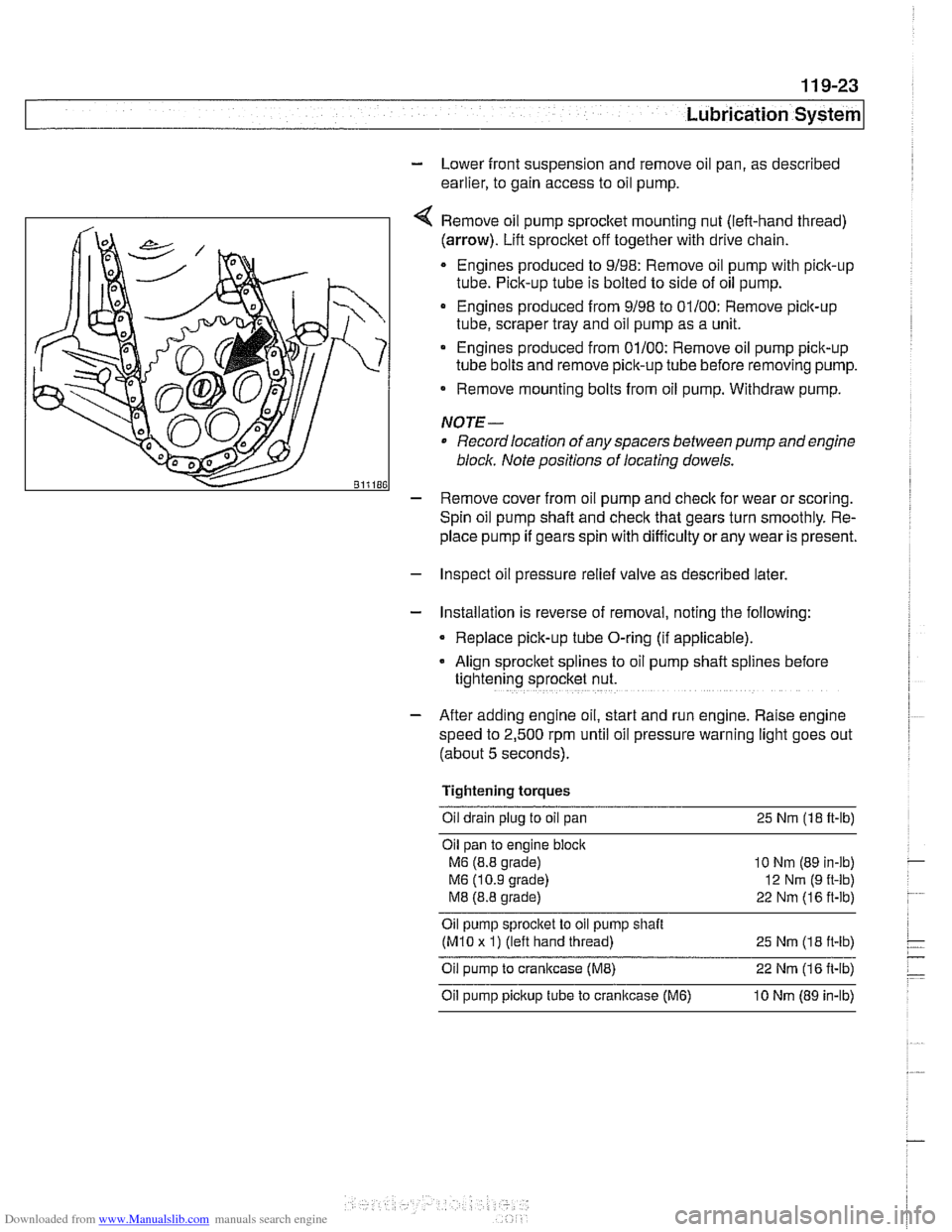
Remove oil pump
sprocket mounting nut (left-hand thread)
(arrow). Lift sprocket off together with drive chain.
Engines produced to 9/98: Remove oil pump with pick-up
tube. Pick-up tube is bolted to side of oil pump.
Engines produced from 9/98 to 01/00: Remove pick-up
tube, scraper tray and oil pump as a unit.
Engines produced from 01/00: Remove oil pump pick-up
tube bolts and remove pick-up tube before removing pump.
Remove mounting bolts from oil pump. Withdraw pump.
NOTE-
Record location of any spacers between pump and engine
bloclc Note positions of locating dowels.
- Remove cover from oil pump and check for wear or scoring.
Spin oil pump shaft and
check that gears turn smoothly. Re-
place pump if gears spin with difficulty
orany wear is present.
- Inspect oil pressure relief valve as described later.
- Installation is reverse of removal, noting the following:
Replace pick-up tube O-ring (if applicable).
- Align sprocket splines to oil pump shaft spl~nes before
tightening sprocket nut.
- After adding engine oil, start and run engine. Raise engine
speed to 2,500 rpm until oil pressure warning light goes out
(about 5 seconds).
Tightening torques Oil drain plug to oil pan 25
Nm (18 ft-lb)
Oil pan to engine
bloclc
M6 (8.8 grade)
M6 (10.9 grade)
M8 (8.8 grade)
10 Nm (89 in-lb)
12
Nrn (9 ft-lb)
22 Nm (16 ft-lb)
Oil pump sprocket to oil pump shait
(M10 x 1) (left hand thread)
25 Nm (1 8 it-lb)
Oil pump to crankcase (ME) 22 Nm (1 6 it-lb)
Oil pump pickup tube to cranltcase (M6) 10 Nm (89 in-lb)
Page 346 of 1002
Downloaded from www.Manualslib.com manuals search engine
11 9-26
/Lubrication System
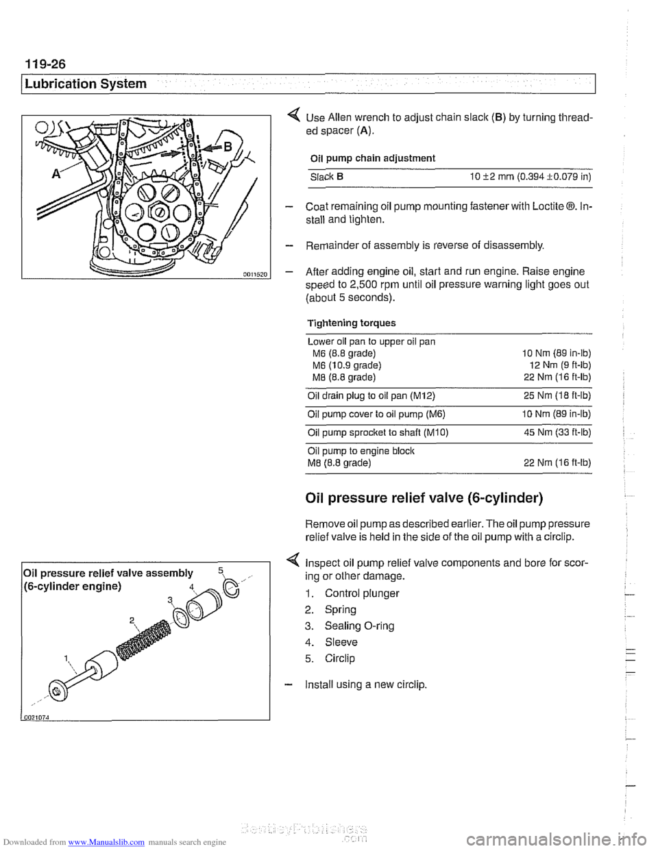
< Use Allen wrench to adjust chain slaclc (B) by turning thread-
ed spacer
(A).
Oil pump chain adjustment
Slack
10 52 mrn (0.394i0.079 in)
- Coat remaining oil pump mounting fastener with Loctite 03. In-
stall and tighten.
- Remainder of assembly is reverse of disassembly.
- After adding engine oil, start and run engine. Raise engine
speed to
2,500 rpm until oil pressure warning light goes out
(about
5 seconds).
Tightening torques
Lower oil pan to upper oil pan
M6 (8.8 grade) 10
Nm (89 in-ib)
M6 (10.9 grade) 12
Nm (9 ft-lb)
M8 (8.8 grade) 22
Nrn (1 6 ft-lb)
Oil drain plug to oil pan (M12) 25 Nm (I8 ft-lb)
Oil pump cover to oil pump
(M6) 10 Nrn (89 in-lb)
Oilpump sprocket to shaft TKO) 45 Nm (33 it-lb)
Oil pump to engine bloclc
M8 (8.8 grade) 22 Nrn (16 ft-lb)
Oil pressure relief valve (&cylinder)
Remove oil
pump as described earlier. The oil pump pressure
relief valve is held in the side of the
oil pump with a circlip.
< Inspect oil pump relief valve components and bore for scor-
4. Sleeve
5. Circlip
- Install using a new circlip.
Oil
pressure relief valve assembly
,- ..., !~. -.-~. - ~- -~!~~-% h. .- .,, /to-cy~~noer engrnej ing or other damage.
1. Control plunger
2. Spring
3. Sealing O-ring