oil reset BMW 540i 2000 E39 Workshop Manual
[x] Cancel search | Manufacturer: BMW, Model Year: 2000, Model line: 540i, Model: BMW 540i 2000 E39Pages: 1002
Page 33 of 1002
Downloaded from www.Manualslib.com manuals search engine
020 Maintenance
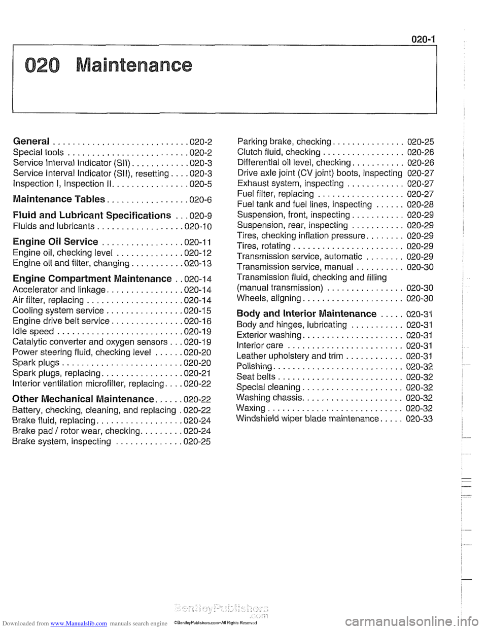
General ........................... .02 0.2
Special tools ........................ .02 0.2
Service Interval Indicator (Sll) ........... .02 0.3
Service Interval Indicator (Sll), resetting ... .02 0.3
Inspection I, Inspection 11 ............... .02 0.5
Maintenance Tables ................ .02 0.6
Fluid and Lubricant Specifications .. .02 0.9
Fluids and lubricants ................. .02 0.10
Engine Oil Service ................ .02 0.1 I
Engine oil. checking level ............. .02 0.12
Engine oil and filter. changing .......... .02 0-13
Engine Compartment Maintenance . .02 0.14
Accelerator and linkage ............... .02 0.14
Air filter. replacing ................... .02 0.1 4
Cooling system service ............... .02 0.15
Engine drive belt service .............. .02 0.16
Idlespeed .......................... 020-19
Catalytic converter and oxygen sensors .. .02 0.19
Power steering fluid, checking level ..... .02 0.20
Spark plugs ........................ .02 0.20
Spark plugs, replacing ................ .02 0.21
Interior ventilation microfilter, replacing ... .02 0.22
Other Mechanical Maintenance ..... .02 0.22
Battery, checking. cleaning. and replacing .02 0-22
Brake fluid. replacing ................. .02 0-24
Brake pad 1 rotor wear. checking ........ .02 0.24
Brake system, inspecting ............. .02 0.25
Parking brake. checking ............... 020-25
Clutch fluid. checking ................. 020-26
Differential oil level. checking ........... 020-26
Drive axle joint (CV joint) boots. inspecting 020-27
Exhaust system. inspecting ............ 020-27
Fuel filter. replacing .................. 020-27
Fuel tank and fuel lines. inspecting ...... 020-28
Suspension. front. inspecting ........... 020-29
Suspension. rear. inspecting ........... 020-29
Tires. checking inflation pressure ........ 020-29
Tires. rotating ....................... 020-29
Transmission service. automatic ........ 020-29
Transmission service. manual .......... 020-30
Transmission fluid. checking and filling
(manual transmission)
................ 020-30
Wheels. aligning ..................... 020-30
Body and Interior Maintenance ..... 020-31
Body and hinges. lubricating ........... 020-31
Exterior washing ..................... 020-31
Interior care ........................ 020-31
Leather upholstery and trim ............ 020-31
Polishing ........................... 020-32
Seat belts .......................... 020-32
Special cleaning ..................... 020-32
Washing chassis ..................... 020-32
Waxing ............................ 020-32
Windshield wiper blade maintenance ..... 020-33
Page 35 of 1002
Downloaded from www.Manualslib.com manuals search engine
Maintenance
Service Interval lndicator (Sll)
The BMW Service Interval lndicator (SII) notifies the driver
when oil change and other service is required. The
Sll dis-
plays the phrase "OIL SERVICE"
or"INSPECTI0N" and 7
light emitting diodes (LEDs) in the Instrumentcluster: 5green,
one yellow and one red.
For the
1997 and later 5 Series, BMW introduced an oil
change interval based on fuel consumption. The advantages
of this system are:
Fuel consumption is an accurate method of determining
engine load and the need for service.
The processing electronics are simple.
Resetting of indicator before the scheduled time will not
affect the time to the next service.
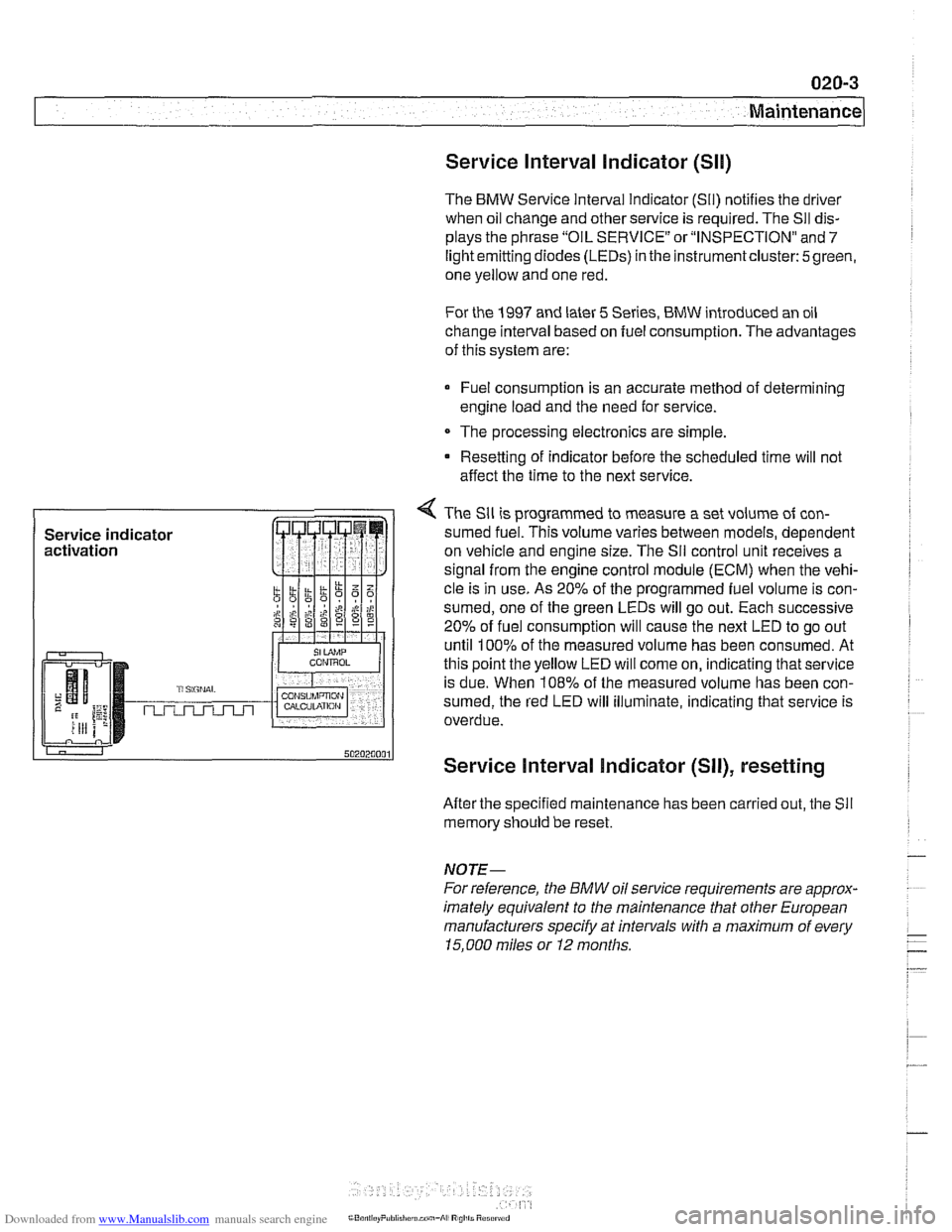
4 The Sll is programmed to measure a set volume of con-
sumed fuel. This volume varies between models, dependent
on vehicle and engine size. The
Sil control unit receives a
signal from the engine control module (ECM) when the vehi-
cle is in use. As
20% of the programmed fuel volume is con-
sumed, one of the green LEDs will go out. Each successive
20% of fuel consumption will cause the next LED to go out
until
100% of the measured volume has been consumed. At
this point the yellow LED will come on, indicating that service
is due. When
108% of the measured volume has been con-
sumed, the red LED will illuminate, indicating that service is
overdue.
Service Interval Indicator (SII), resetting
After the specified maintenance has been carried out, the Sll
memory should be reset.
NOTE-
For reference, the BMW oil service requirements are approx-
imately equivalent to the maintenance tliat other European
manufacturers specify at intervals with a maximum of every
15.000 miles or I2 months.
Page 36 of 1002
Downloaded from www.Manualslib.com manuals search engine
020-4
Maintenance
1997 to 2000 models
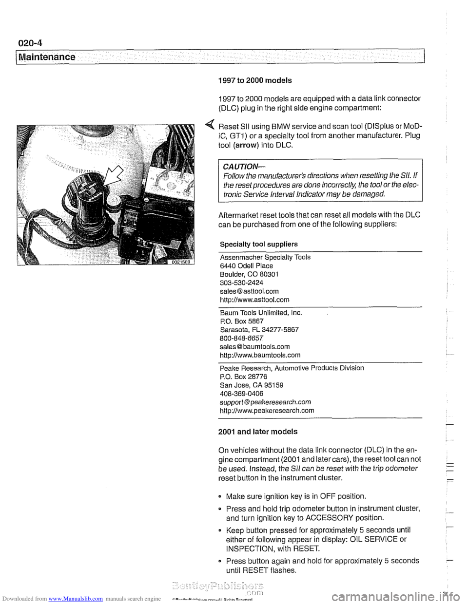
1997 to 2000 models are equipped with a data link connector
(DLC) plug in the right side engine compartment:
Reset
SII using BMW service and scan tool (DISplus or MoD-
iC, GTI) or a specialty tool from another manufacturer. Plug
tool (arrow) into DLC.
CAUTION-
Follow the manufacturer's directions when resetting the Sll. If
the reset procedures are done
incorrect& the tool or the elec-
tronic Service Interval Indicator
may be damaged.
Aftermarket reset tools that can reset all models with the DLC
can be purchased from one of the following suppliers:
Specialty tool suppliers
Assenmacher Specialty Tools
6440
Odell Place
Boulder, CO 80301
303-530-2424
[email protected] http://www.asttool.com
Baum Tools Unlimited,
Inc.
P.O. Box 5867
Sarasota, FL 34277-5867
800-848-6657
[email protected]
http://www.baumtools.com
Peake Research. Automotive Products Division
P.O. Box 28776
San Jose, CA 95159
408-369-0406
support @peakeresearch.com
http://www.peal~eresearch.com
2001 and later models
On vehicles without the data link connector (DLC) in the en-
gine compartment (2001 and latercars), the reset tool can not
be used. Instead, the
Sll can be reset with the trip odometer
reset button in the instrument cluster.
Make sure ignition key is in OFF position.
* Press and hold trip odometer button in instrument cluster,
and turn ignition key to ACCESSORY position.
Keep
button pressed for approximately 5 seconds until
either of following appear in display: OIL SERVICE or
INSPECTION, with RESET.
Press button again and
hold for approximately 5 seconds
until RESET flashes.
Page 37 of 1002
Downloaded from www.Manualslib.com manuals search engine
Maintenance
0 Service due is shown with RESET if the measured con-
sumption limit has been reached and resetting is possible.
If RESET is not shown, the minimum limit has not been
reached and resetting is not possible.
While display is flashing, press button briefly to reset
Sll.
After display has shown new interval, the following will
appear in display for approximately
2 seconds: END SIA.
NOTE-
The system can only be reset again after the vehicle has
been driven approximately 50 to
75 miles (consumes at
least2.5gallons of fuel). If the display shows RESETwhen
resetting, the minimum driving distance has been fulfilled
and the system can be reset again.
0 It is possible to interrupt and end the reset procedure by
changing the position of the ignition
ley.
lnspection I, lnspection II
The Service Interval Indicator (SII) signals the need for main-
tenance and inspection. There are two sets
of inspection re-
quirements, alternating throughout a car's maintenance
history. If the last inspection interval was lnspection I, the next
inspection interval (following an oil service) will be lnspection
11, the next after that will be lnspection I, and so on.
lnspection
I tasks are listed in Table b. lnspection I Service.
lnspection
II includes most of the tasks from lnspection I with
additional lnspection
II tasks. A complete listing of lnspection
II tasks is in Table c. lnspection I1 Service.
NOTE-
For reference, the BMW lnspection I and lnspection I1 re-
quirements are approximately equivalent to the maintenance
requirements that other European manufacturers specify.
ln-
spection I is normally due at intervals with a maximum of
30,000 miles or
24 months. lnspection I1 is normally due at
intervals with a maximum of 60,000 miles or
48 months.
Page 38 of 1002
Downloaded from www.Manualslib.com manuals search engine
Maintenance
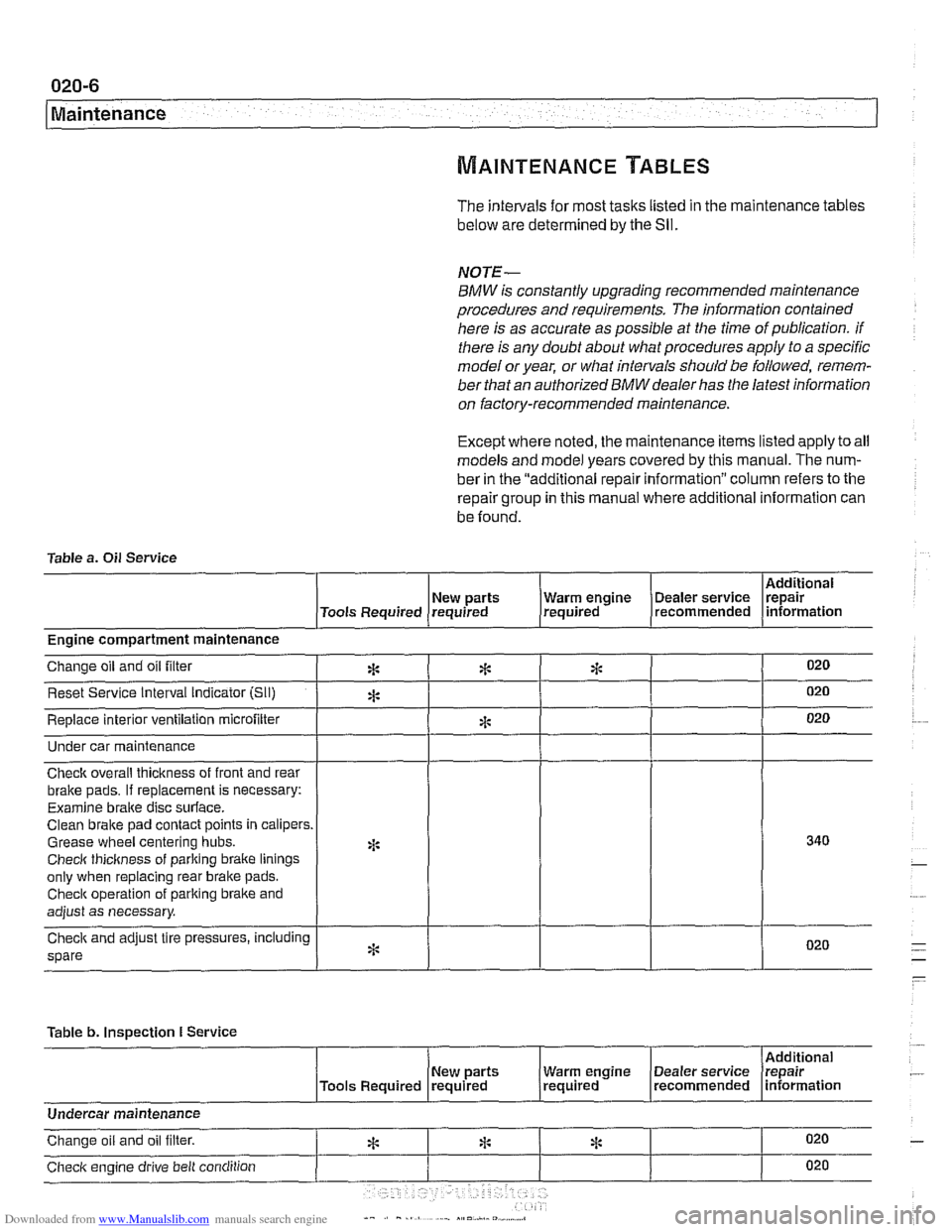
The intervals for most tasks listed in the maintenance tables
below are determined by the Sll.
NOTE-
BMW is constantly upgrading recommended maintenance
procedures and requirements.
The information contained
here is as accurate as possible at the time of publication. if
there is any doubt about what procedures apply to a specific
model or year, or what intervals should be followed, remem-
ber that an authorized
BMW dealer has the latest information
on factory-recommended maintenance.
Except where noted, the maintenance items listed apply to all
models and model years covered by this manual. The num-
ber in the "additional repair information" column refers to the
repair group in this manual where additional information can
be found.
Table a.
Oil Service
I I I I I Additional
( New parts (Tools Required requrred
Under car maintenance
1 I I I I
I I - I I
Engine compartment maintenance
Check overall thickness of front and rear
bralte pads.
If replacement is necessary:
Examine
braite disc surface.
Clean brake pad contact points in calipers.
Grease wheel centering hubs.
Checlc thickness of parking braite linings
only when replacing rear brake pads.
Checlc operation of parking brake and
adjust as necessary.
spare
Table b.
Inspection I Service
I 1 I I [Additional
020
020
020
New parts Warm engrne Dealer service Irepair , /Tools Required (required (required . (recommended lnformatlon
Change oil and oil filter
Reset Service Interval indicator [Sli)
Replace interior ventilation microfilter
*
A
*
*
*
I I I I I
Undercar maintenance
Checlc engine drive belt condition 020
ri: * Change oil and oil filter. 020 *
Page 213 of 1002
![BMW 540i 2000 E39 Workshop Manual Downloaded from www.Manualslib.com manuals search engine
-
. - - -- Cylinder Head and valvetrain]
Turn engine over twice in direction of rotation until cylinder 1
intake and exhaust camshaft BMW 540i 2000 E39 Workshop Manual Downloaded from www.Manualslib.com manuals search engine
-
. - - -- Cylinder Head and valvetrain]
Turn engine over twice in direction of rotation until cylinder 1
intake and exhaust camshaft](/img/1/2822/w960_2822-212.png)
Downloaded from www.Manualslib.com manuals search engine
-
. - - -- Cylinder Head and valvetrain]
Turn engine over twice in direction of rotation until cylinder 1
intake and exhaust camshaft lobes (arrows) face each other.
- Lock crankshaft in TDC position with BMW special tool
11 2 300.
4 Place BMW special tool set 11 3 240 over camshafts and
measure clearances.
NOTE-
@ If the exhaust side of the tool (A) is not flush with the head,
camshaft timing is incorrect. Reset camshaft timing as de-
scribed in 11
7 Camshaft Timing Chain.
Due to flexible sprocket design, VANOS unit tolerances
and play in the VANOS splines, when the camshaft timing
is set correctly, the intake side of special tool set
11 3 240
(B) may be up to 1 mm (0.04 in.) above the suiface of the
cylinder head. This is normal. Reassemble engine. Other-
wise, reset camshaft timing as describedin 1
l?Camshaft
Timing Chain.
- Remove BMW special tool 11 6 150 from front of cylinder
head.
4 Clean contact edges of cylinder head face and VANOS unit
and apply a thin coat of Three Bond
12090 or equivalent
sealing compound to surfaces.
CAUTION-
Male sure all gasket material is removed from face of cyl-
inder head. Clean sealing face and keep free of oil.
Check locating dowel
(A) and dowel sleeve (B) at top
of cylinder head for damage or incorrect installation.
- Using a new steel gasket, install VANOS unit to front of cyi-
inder head. See 117 Camshaft Timing Chain.
NOTE-
If VANOS control unit is being replaced, be sure to check and
adjust camshaft timing as described in 117 Camshaft Tim-
ing Chain.
- Reinstall engine lifting eye.
- Reconnect electrical harness connectors to camshaft posi-
tion sensors and
VANOS solenoid valves.
Page 428 of 1002
Downloaded from www.Manualslib.com manuals search engine
130-38
Fuel Injection
Throttle cable, adjusting
(MS 42.0)
The throttle assembly on MS 42.0 cars uses a throttle cable.
The cable should be adjusted any time it is disconnected or
replaced. This procedure requires the factory scan tool or an
equivalent to read and adjust throttle angle. It is recommend-
ed the procedure be done by an authorized
BMW dealer ser-
vice department
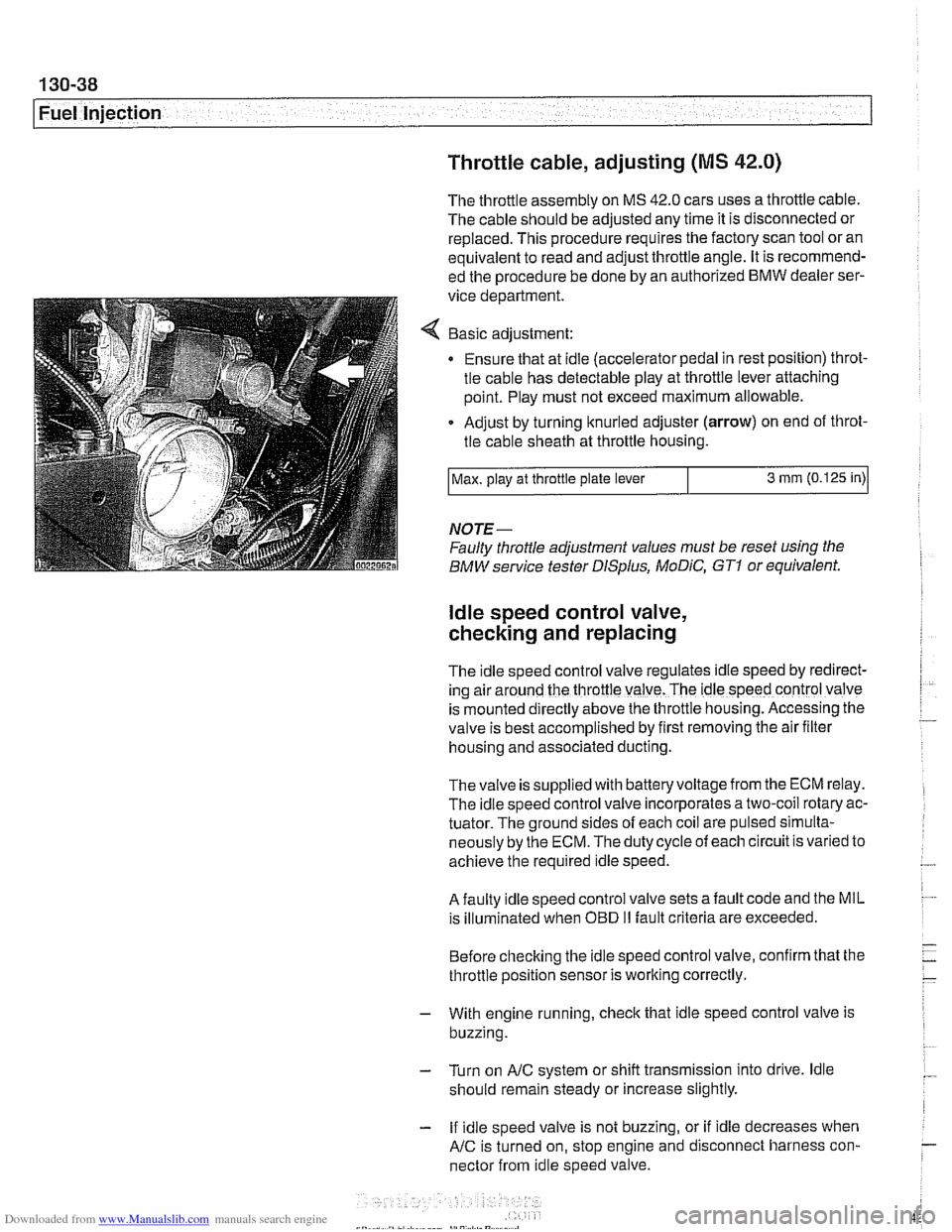
Basic adjustment:
Ensure that at idle (accelerator pedal in rest position) throt-
tle cable has detectable play at throttle lever attaching
point. Play must not exceed maximum allowable.
Adjust by turning knurled adjuster
(arrow) on end of throt-
tle cable sheath at throttle housing.
NOTE-
Faulty throttle adjustment values must be reset using the
BMW service tester
DISplus, MoDiC, GTI or equivalent.
Max.
play at throttle plate lever
ldle speed control valve,
checking and replacing
3 mm (0.125 in)
The Idle speed control valve regulates Idle speed by red~rect-
ing air around the throttle valve. The ldle speed control valve
is mounted
d~rectly above the throttle housing. Accessing the
valve is best accomplished by
flrst removing the air fllter
housing and associated ducting.
Thevalve is supplied with batteryvoltage from the ECM relay.
The idle speed control valve incorporates a two-coil rotary ac-
tuator. The ground sides of each coil are pulsed simulta-
neously by the ECM. The duty cycle of each circuit is varied to
achieve the required idle speed.
A faulty idle speed control valve sets a fault code and the MIL
is illuminated when
OED II fault criteria are exceeded.
Before checking the idle speed control valve, confirm that the
throttle position sensor is working correctly.
- With engine running, check that idle speed control valve is
buzzing.
- Turn on AIC system or shift transmission into drive. ldle
should remain steady or increase slightly.
- If idle speed valve is not buzzing, or if idle decreases when
AIC is turned on, stop engine and disconnect harness con-
nector from idle speed valve.
Page 561 of 1002
Downloaded from www.Manualslib.com manuals search engine
Clutch
Clutch, installing (used SAC components)
When reinstalling a previously used self-adjusting clutch
(SAC), special tools are needed to reset the self-adjusting
ring to its original position.
CAUTIOI\C
Avoidcontaminating clutch friction suifaces with oilorgrease.
Do not touch these
suifaces.
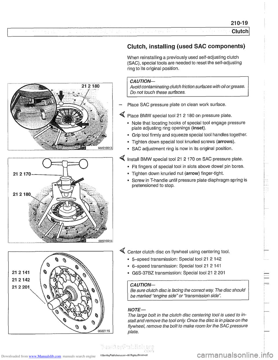
- Place SAC pressure plate on clean worlc suriace.
4 Place BMW special tool 21 2 180 on pressure plate
Note that locating hoolts of special tool engage pressure
plate adjusting ring openings
(inset).
Grip tool firmly and squeeze special tool handles together.
Tighten down special tool knurled screws (arrows).
- SAC adjustment ring is now in its original position.
4 Install BMW special tool 21 2 170 on SAC pressure plate.
Fit fingers of special tool in slots above dowel pin bores.
Tighten down knurled nut (arrow) finger-tight.
Screw in T-handle until pressure plate diaphragm spring is
pretensioned to stop.
< Center clutch disc on flywheel using centering tool.
5-speed transmission: Special tool 21 2 142
6-speed transmission: Special tool 21 2 141
G6S-3762 transmission: Special tool 21 2 201
CAUTION--
Be sure clutch disc is lacing the correct way The disc should
be
marked 'kngine side" or 'Transmission side':
NOTE-
The large bolt in the clutch disc centering tool is used to in-
stalland remove the tool only Once the disc is in place on tlie
flywheel, remove the bolt to male room for the SACpressure
plate.