pulley BMW 540i 2000 E39 Workshop Manual
[x] Cancel search | Manufacturer: BMW, Model Year: 2000, Model line: 540i, Model: BMW 540i 2000 E39Pages: 1002
Page 48 of 1002
Downloaded from www.Manualslib.com manuals search engine
020-1 6
Maintenance
loose, hose is damaged, or connection is dirty or corroded.
Dried coolant has achalky appearance. Hoses should be firm
and springy. Replace any hose that is cracked, has become
soft and limp, or has been contaminated by oil.
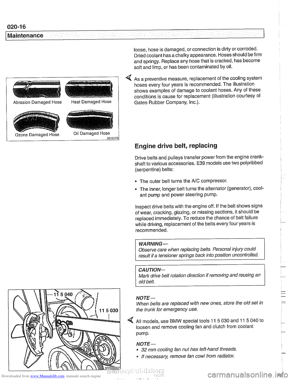
4 As a preventive measure, replacement of the cooling system
hoses every four years is recommended. The illustration
shows examples of damage to coolant hoses. Any of these
conditions is cause for replacement (illustration courtesy of
/ Abrasion Damaged Hose Heat Damaged Hose 1 Gates Rubber Company, I~c.).
Engine drive belt, replacing
Drive belts and pulleys transfer power from the engine crank-
shaft to various accessories.
E39 models use two polyribbed
(serpentine) belts:
The outer belt turns the
NC compressor.
0 The inner, longer belt turns the alternator (generator), cool-
ant pump and power steering pump.
Inspect drive belts with the engine off. If the belt shows signs
of wear, cracking, glazing, or missing sections, it should be
replaced
immediately. To reduce the chance of belt failure
while driving, replacement of the belts every four years is
recommended.
WARNING -
Observe care when replacing belts. Personal injury could
result if a tensioner springs back into position uncontrolled.
CA UTIOI\C
Mark drive belt rotation direction if removing and reusing an
old belt.
NOTE-
When belts are replaced with new ones, store the old set in
the trunk for emergency use.
All models, use
BMW special tools 11 5 030 and 11 5 040 to
loosen and remove cooling fan and clutch from coolant
pump.
NOTE-
32 mm cooling fan nut has left-hand threads
If necessary, remove fan cowl from radiator.
Page 50 of 1002
Downloaded from www.Manualslib.com manuals search engine
020-1 8
Maintenance
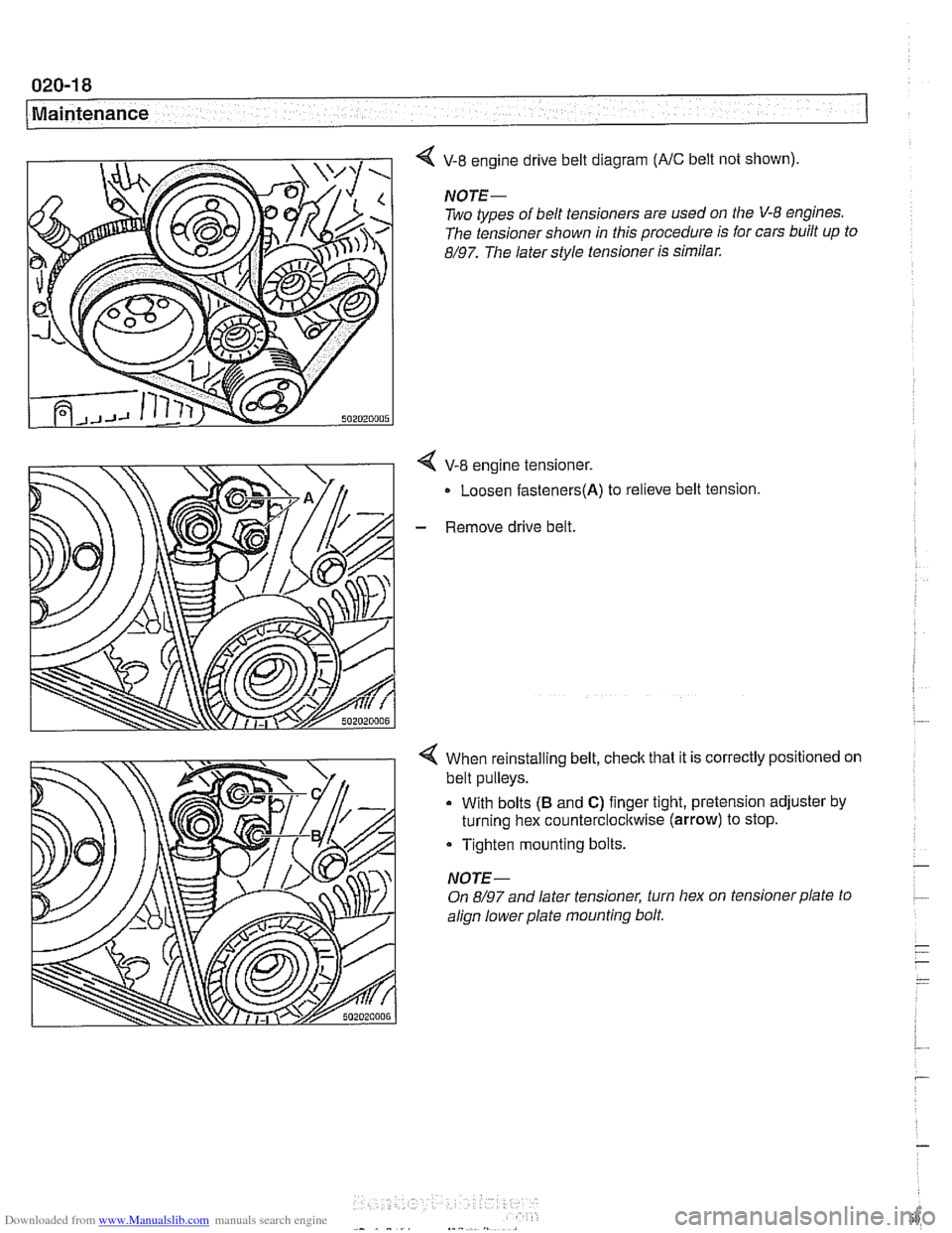
V-8 engine drive belt diagram (NC belt not shown).
NOTE-
Two types of belt tensioners are used on the V-8 engines.
The tensioner shown in this procedure is for cars built up to
8/97. The later style tensioner is similar.
4 V-8 engine tensioner.
Loosen
fasteners(A) to relieve belt tension
- Remove drive belt.
4 When reinstalling belt, check that it is correctly positioned on
belt pulleys.
With bolts
(B and C) finger tight, pretension adjuster by
turning hex counterclocltwise
(arrow) to stop.
Tighten mounting bolts.
NOTE-
On 8/97 and later tensioner, turn hex on tensioner plate to
align lowerplate mounting bolt.
Page 51 of 1002
Downloaded from www.Manualslib.com manuals search engine
Maintenance
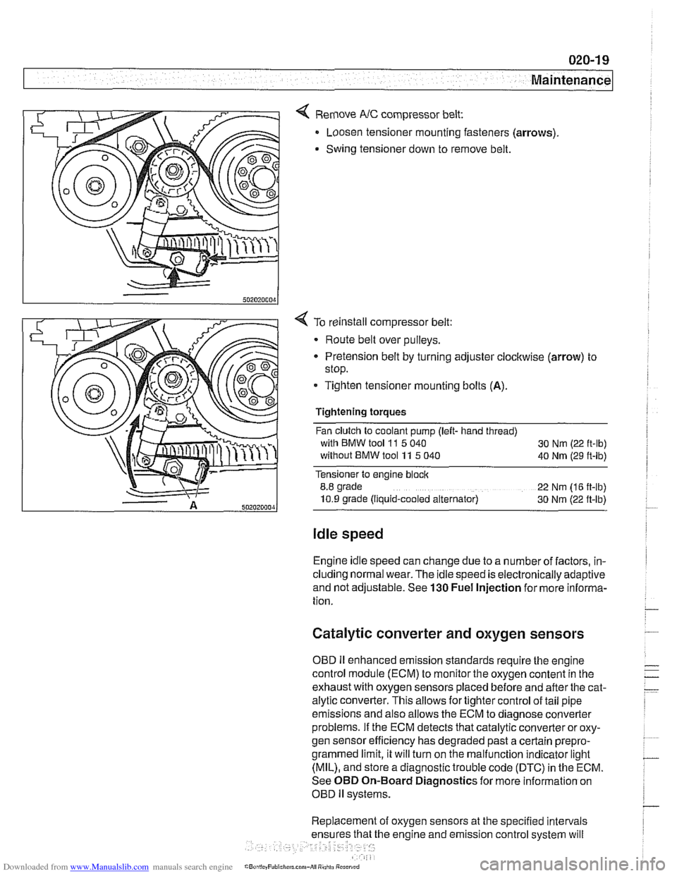
< Remove NC compressor belt:
Loosen tensioner mounting fasteners (arrows)
Swing tensioner down to remove belt.
4 To reinstall compressor belt:
Route belt over pulleys.
* Pretension belt by turning adjuster clockwise (arrow) to
stop.
- Tighten tensioner mounting bolts (A).
Tightening torques
Fan clutch to coolant pump (left- hand thread)
with BMW tool
11 5 040
30 Nm (22 ft-lb)
without BMW tool 11 5 040
40 Nm (29 ft-lb)
Tensioner to engine block
8.8 grade
22 Nm (16 ft-lb)
10.9 grade (Ilquid-cooled alternator) 30 Nm (22 ft-lb)
Idle speed
Engine idle speed can change due to a number of factors, in-
cluding normal wear. The idle speed is electronically adaptive
and not adjustable. See
130 Fuel Injection for more informa-
tion.
Catalytic converter and oxygen sensors
OBD II enhanced emission standards require the engine
control module (ECM) to monitor the oxygen content in the
exhaust with oxygen sensors placed before and after the cat-
alytic converter. This allows for tighter control of tail pipe
emissions and also allows the ECM to diagnose converter
problems. If the ECM detects that catalytic converter or oxy-
gen sensor efficiency has degraded past a certain
prepro-
grammed limit, it will turn on the malfunction indicator light
(MIL), and store a diagnostic trouble code (DTC) in the ECM.
See OBD On-Board Diagnostics for more information on
OBD
ll systems.
Replacement of oxygen sensors at the specified intervals
he engine and emission control system will
Page 85 of 1002
Downloaded from www.Manualslib.com manuals search engine
Engine Removal and Installation
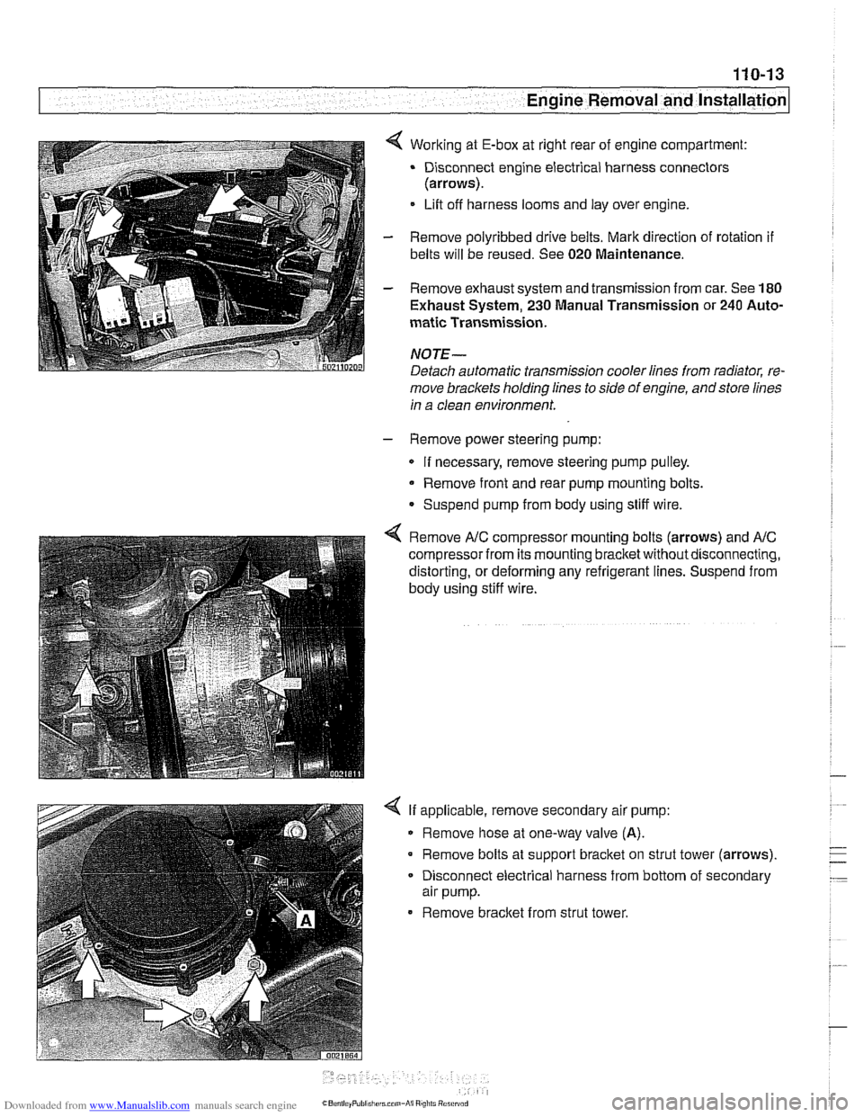
4 Working at E-box at right rear of engine compartment:
Disconnect engine electrical harness connectors
(arrows).
Lift off harness looms and lay over engine.
- Remove polyribbed drive belts. Mark direction of rotation if
belts will be reused. See 020 Maintenance.
- Remove exhaust system and transmission from car. See 180
Exhaust System, 230 Manual Transmission or 240 Auto-
matic Transmission.
NOJE-
Detach automatic transmission cooler lines from radiator, re-
move brackets holding lines to side of engine, andstore lines
in a clean environment.
- Remove power steering pump:
If necessary, remove steering pump pulley.
Remove front and rear pump mounting bolts.
Suspend pump from body using stiff wire.
4 Remove A/C compressor mounting bolts (arrows) and AIC
compressor from its mounting bracketwithoutdisconnecting,
distorting, or deforming any refrigerant lines. Suspend from
body using stiff wire.
4 If applicable, remove secondary air pump:
Remove hose at one-way valve
(A).
Remove bolts at support bracket on strut tower (arrows).
- Disconnect electrical harness from bottom of secondary
air pump.
Remove bracket from strut tower.
Page 87 of 1002
Downloaded from www.Manualslib.com manuals search engine
110-15
Engine Removal and lnstallation
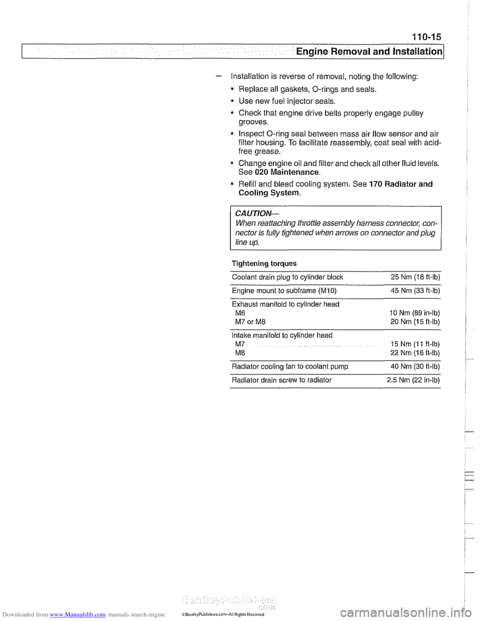
- Installation is reverse of removal, noting the following:
Replace all gaskets. O-rings and seals.
Use new fuel injector seals
Check that engine drive belts properly engage pulley
grooves.
Inspect O-ring seal between mass air flow sensor and air
filter housing. To facilitate reassembly, coat seal with acid-
free grease.
Change engine oil and filter and
check all other fluid levels.
See
020 Maintenance.
Refill and bleed cooling system. See
170 Radiator and
Cooling System.
CAUTION--
When reattaching throttle assembly harness connectoc con-
nector is
fuNy tightened when arrows on connector and plug
line up.
Tightening torques
Coolant drain plug to cylinder block
25 Nm (18 ft-lb)
Engine mount to
subframe (M10) 45 Nm (33 ft-ib)
Exhaust manifold to cylinder head
M6 10 Nm (89 in-lb)
M7 or ME 20 Nm (15 ft-lb)
Intake manifold to cylinder head
M7 15 Nm (I 1 ft-lb)
ME 22 Nm (16 ft-lb)
Radiator cooling fan to coolant pump
40 Nm (30 ft-lb)
Radiator drain screw to radiator
2.5 Nm (22 in-lb)
Page 93 of 1002
Downloaded from www.Manualslib.com manuals search engine
--
-- Engine Removal and installation' -
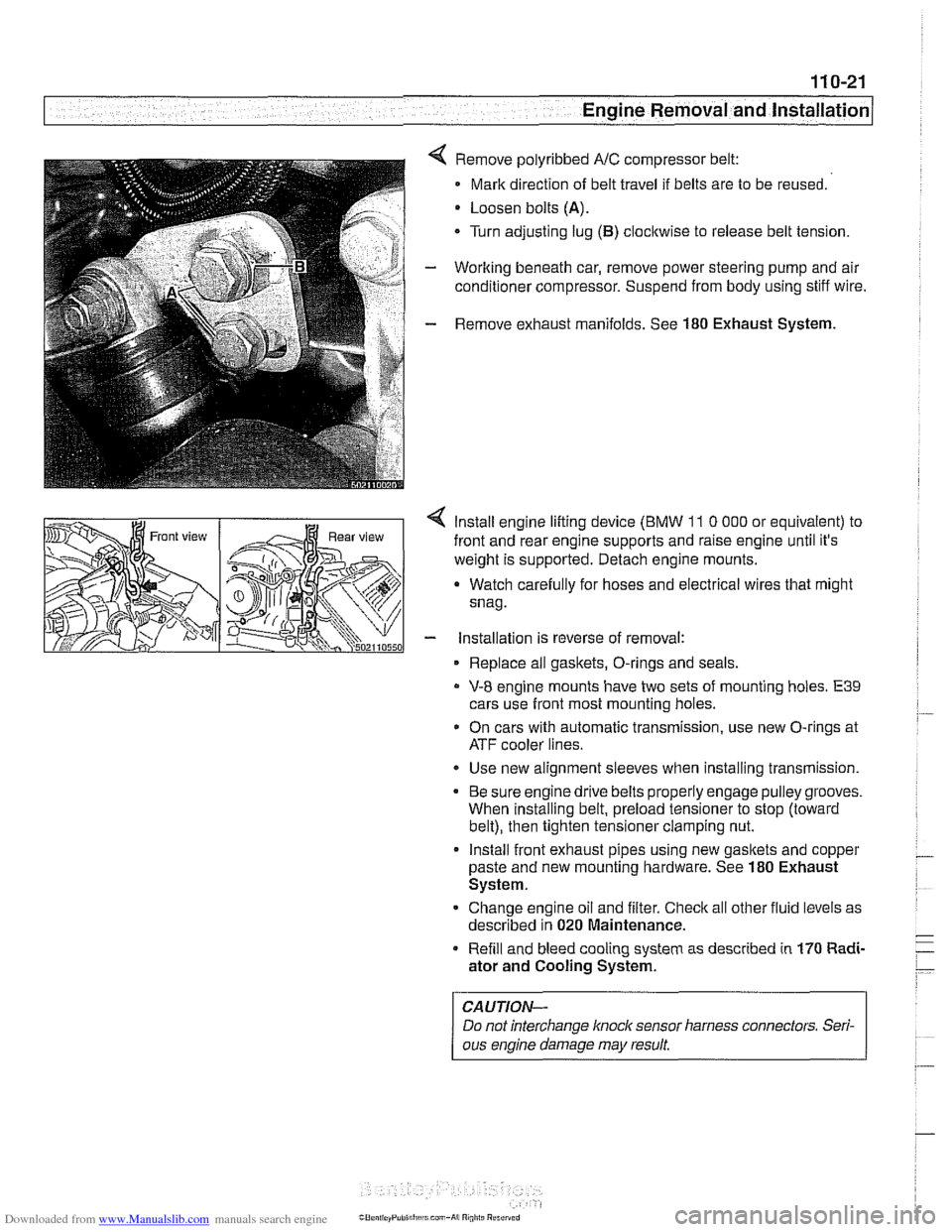
Remove polyribbed A/C compressor belt:
Mark direction of belt travel if belts are to be reused.
Loosen bolts
(A).
Turn adjusting lug (B) clocltwise to release belt tension.
Working beneath car, remove power steering pump and air
conditioner compressor. Suspend from body using stiff wire.
Remove exhaust manifolds. See
180 Exhaust System.
< lnstall engine lifting device (BMW 11 0 000 or equivalent) to
front and rear engine supports and raise engine until it's
weight is supported. Detach engine mounts.
a Watch carefully for hoses and electrical wires that might
snag.
- installation is reverse of removal:
Replace all gaskets, O-rings and seals.
V-8 engine mounts have two sets of mounting holes. E39
cars use front most mounting holes.
* On cars with automatic transmission, use new O-rings at
ATF cooler lines.
Use new alignment sleeves when installing transmission.
Be sure engine drive belts properly engage pulley grooves.
When installing belt, preload tensioner to stop (toward
belt), then tighten tensioner clamping nut.
lnstall front exhaust pipes using new gasltets and copper
paste and new mounting hardware. See
180 Exhaust
System.
Change engine oil and filter. Check all other fluid levels as
described in
020 Maintenance.
Refill and bleed cooling system as described in
170 Radi-
ator and Cooling System.
CAUTION-
Do not interchange knoclc sensor harness connectors. Seri-
ous engine damage may result
Page 139 of 1002
Downloaded from www.Manualslib.com manuals search engine
Cylinder Head Removal and Installation
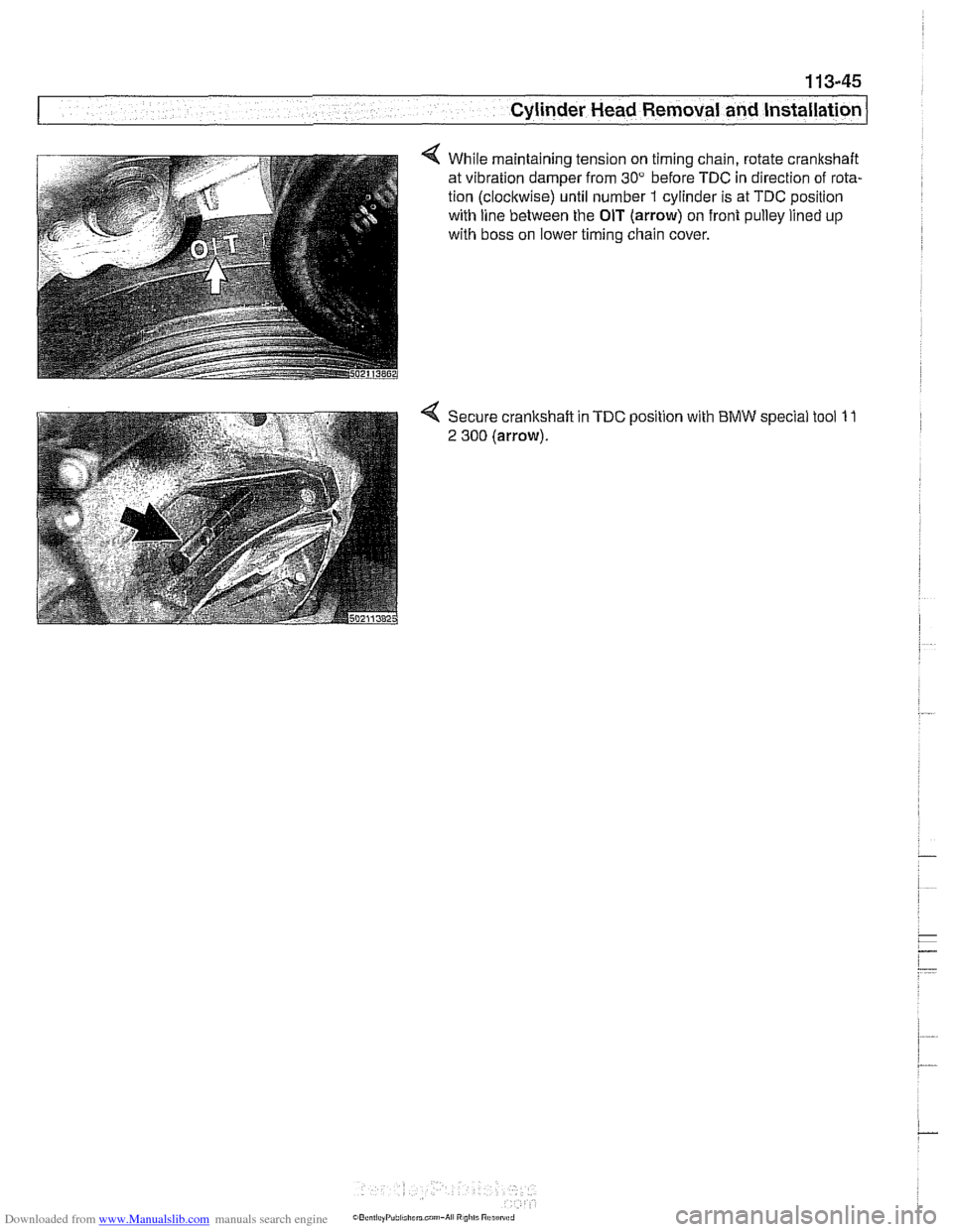
4 While maintaining tension on timing chain, rotate crankshaft
at vibration damper from
30" before TDC in direction of rota-
tion (clockwise) until number
1 cylinder is at TDC position
with line between the
OIT (arrow) on front pulley lined up
with boss on lower timing chain cover.
Page 206 of 1002
Downloaded from www.Manualslib.com manuals search engine
~ ~. --
Cylinder Head and Valvetrain .-
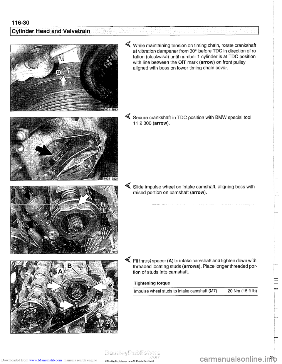
4 While maintaining tension on timing chain, rotate crankshaft
at vibration dampener from
30" before TDC in direction of ro-
tation (clockwise) until number
1 cylinder is at TDC position
with line between the OIT mark (arrow) on front pulley
aligned with boss on lower timing chain cover.
4 Secure crankshaft in TDC position with BMW special tool
11 2 300 (arrow).
Slide impulse wheel on intake camshaft, aligning boss with
raised portion on camshaft (arrow).
Fit thrust spacer
(A) to intalte camshaft and tighten down with
threaded locating studs (arrows). Place longer threaded por-
tion of studs into camshaft.
Tightening torque
Impulse wheel studs to intake camshaft (M7)
20 Nm (15 ft-lb)
Page 220 of 1002
Downloaded from www.Manualslib.com manuals search engine
..
ICylinder Head and Valvetrain -.I
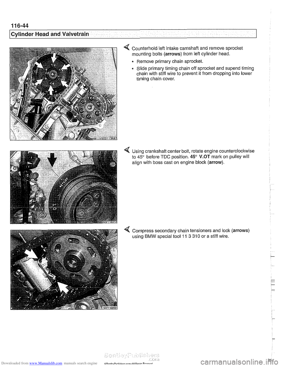
4 Counterhold left intake camshaft and remove sprocket
mounting bolts
(arrows) from left cylinder head.
Remove primary chain sprocket.
Slide primary timing chain off sprocket and
supend timing
chain with stiff wire to prevent it from dropping into lower
timing chain cover.
4 Using cranltshaft center bolt, rotate engine counterclockwise
to
45" before TDC position. 45" V.OT mark on pulley will
align with boss cast on engine block
(arrow).
4 Compress secondary chain tensioners and lock (arrows)
using BMW special tool 11 3 310 or a stiff wire.
Page 243 of 1002
Downloaded from www.Manualslib.com manuals search engine
Camshaff Timing Chain
NOTE-
Mark direction of belt rotation if reusing belt.
- Remove vibration damper mounting bolts and remove vibra-
tion damper and pulley from hub.
NOTE- The M52
6-cylinder engine uses a 2-piece vibration damper
and hub assembly.
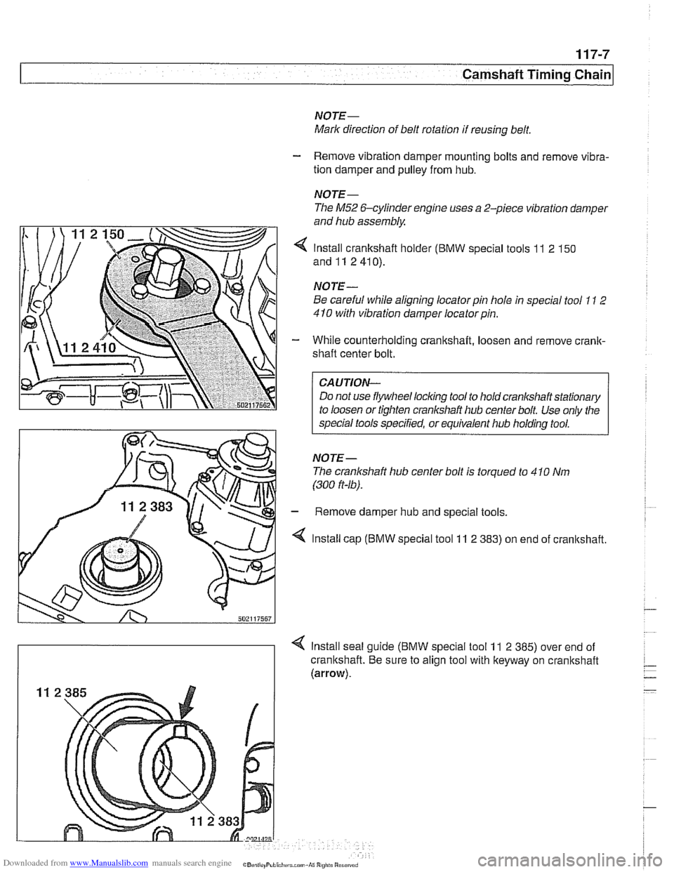
4 Install crankshaft holder (BMW special tools 11 2 150
and11 2410).
NOTE
-
Be careful while aligning locator pin hole in special tool 11 2
410 with vibration damper locatorpin.
- While counterholding crankshaft, loosen and remove crank-
shaft center bolt.
CAUTION-
Do not use flywheel locking tool to hold crankshaft stationary
to loosen or tighten crankshaft hub center bolt Use only the
special tools specified, or equivalent hub holding tool.
NOTE- The cranlshaft hub center bolt is torqued to 4
10 Nm
(300
ft-16).
- Remove damper hub and special tools.
4 Install cap (BMW special tool 11 2 383) on end of cranltshaft.
4 Install seal guide (BMW special tool 11 2 385) over end of
crankshaft. Be sure to align tool with keyway on crankshaft
(arrow).