wiring BMW 540i 2000 E39 Workshop Manual
[x] Cancel search | Manufacturer: BMW, Model Year: 2000, Model line: 540i, Model: BMW 540i 2000 E39Pages: 1002
Page 3 of 1002
Downloaded from www.Manualslib.com manuals search engine
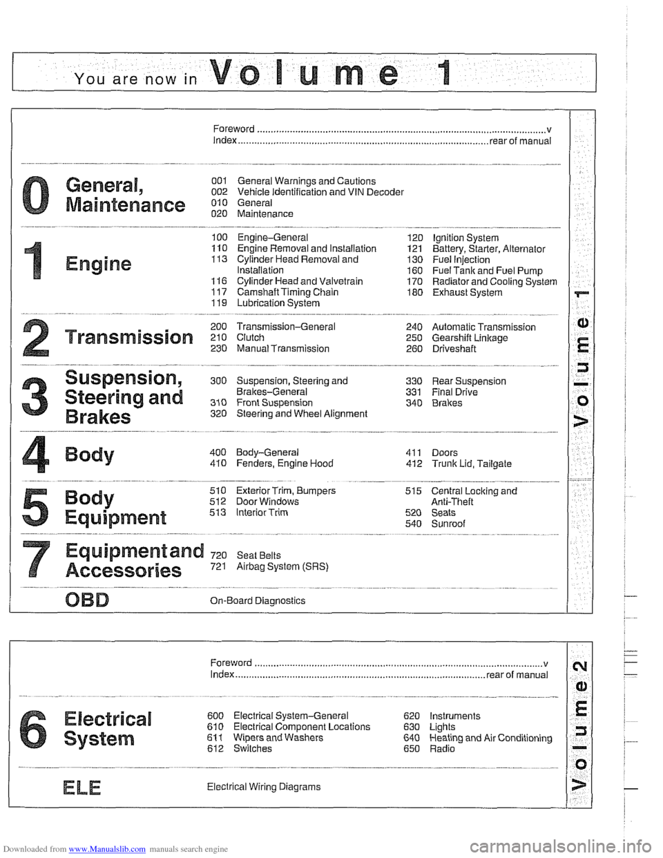
YOU are now in Volume I
I
Foreword ................... .. ........................................................................\
.......... v
Index
........................ .. ................................................................ rear of manual
General, 001 General Warnings and Cautions 002 Vehicle Identification and VIN Decoder
Maintenance OiO 020 Maintenance
Engine
100 Engine-General 110 Engine Removal and Installation
113 Cylinder Head Removal and
Installation
116 Cyiinder Head and Valvetrain 117 Camshaft Timing Chain
119 Lubrication System
200 Transmission-General
2 Transmission 210 clutch 230 ManualTransmission
I20 Ignition System
121 Battery, Starter, Alternator
130 Fuel Injection
160 Fuel Tank and Fuel Pump 170 Radiator and Cooling System
180 Exhaust System
240 Automatic Transmission
250 Gearshift Linkage 260 Driveshaft
Suspension, 300 Suspension, Steering and 330 Rear Suspension
Brakes-General 331 Final Drive
Steering and No Front Suspension 340 Brakes
320 Steering and Wheel Alignment
400 Body-General
410 Fenders, Engine Hood 411 Doors
412 Trunk Lid, Tailgate
510 Exterior Trim, Bumpers 512 Door Windows
Equipment 513 Interior Trim
7
Equipment and 720 seat Belts
Accessories 721 Airbag System (SRS)
OBD On-Board Diagnostics
. ............ ..
515 Central Lociting and
Anti-Theft
520 Seats 540 Sunroof
.................................................................... Foreword .............................. .. v
Index ................... .. ................................................................ rear of manual
Electrical
6 system
600 Electrical System-General 620 Instruments
610 Electrical Comoonent Locations 630 Liohts
611 wipers and washers 612 Switches eati in^ and Air Conditioning
Radio
. ........... ........ .........................
Electrical Wiring Diagrams
Page 12 of 1002
Downloaded from www.Manualslib.com manuals search engine
01 0-2
General
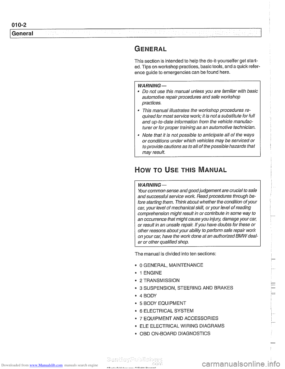
This section is intended to help the do-it-yourselfer get start-
ed. Tips on workshop practices, basic tools, and a quick refer-
ence guide to emergencies can be found here.
WARNING-
Do not use this manual unless you are familiar with basic
automotive repair procedures and safe workshop
practices.
0 This manual illustrates the worl
and up-to-date information from the vehicle manufac-
turer or for proper training as an automotive technician.
Note that it is not possible to anticipate all of the ways
or conditions under which vehicles may be serviced or
to provide cautions as to all of the possible hazards that
may result.
MOW TO USE THIS MANUAL
WARNING -
Your common sense and goodjudgement are crucial to safe
and successful service
work. Read procedures through be-
fore starting them. Think about whether the condition of your
cac your level of mechanical skill, or pour level of reading
comprehension might result in or contribute in some way to
an occurrence that might cause you injury, damage your car;
or result in an unsafe repair. If you have doubts for these or
other reasons about your ability to perform safe repair work
on your car; have the work done at an authorized
BMW deal-
er or other qualified shop.
The manual is divided into ten sections:
0 GENERAL, MAINTENANCE
0 I ENGINE
2 TRANSMISSION
3 SUSPENSION, STEERING AND BRAKES
4 BODY
5 BODY EQUIPMENT
6 ELECTRICAL SYSTEM
7 EQUIPMENT AND ACCESSORIES
- ELE ELECTRICAL WIRING DIAGRAMS
OBD ON-BOARD DIAGNOSTICS
Page 13 of 1002
Downloaded from www.Manualslib.com manuals search engine
General
0 GENERAL, MAINTENANCE covers general vehicle infor-
mation
(010 General) as well as the recommended mainte-
nance schedules and service procedures to perform BMW
scheduled maintenance
work (020 Maintenance).
The next seven sections
(1 through 7) are repair based and
organized by three digit repair groups. Most major sections
begin with a GENERAL repair group,
e.g. 100 Engine-Gen-
eral. These "00 (double zero) groups contain descriptive the-
ory of operation and system troubleshooting information. The
remainder of the repair groups within a section contain the
service and repair information. The last two sections contain
detailed electrical wiring schematics and OBD
II scan tool and
diagnostic information.
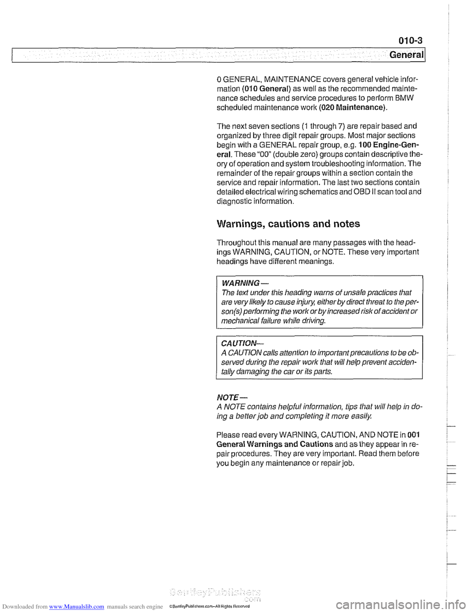
Warnings, cautions and notes
Throughout this manual are many passages with the head-
ings WARNING, CAUTION, or NOTE. These very important
headings have different meanings.
WARNING-
The text under this heading warns of unsafe practices that
are very
likely to cause injury, either by direct threat to the per-
son(~) performing the work
orby increasedrisl( of accident or
mechanical failure while
drivinq.
CAUTION-
A CAUTION calls attention to importantprecautions to be ob-
senfed during the repair work that will help prevent acciden-
tally damaging the car or its parts.
NOTE-
A NOTE contains helpful information, tips that will help in do-
ing a betterjob and completing it more easily.
Please read every WARNING, CAUTION, AND NOTE in
001
General Warnings and Cautions and as they appear in re-
pair procedures. They are very important. Read them before
you begin any maintenance or repair job.
Page 20 of 1002
Downloaded from www.Manualslib.com manuals search engine
01 0-1 0
General
Electrical testing
Many electrical problems can be understood and solved with
only a little fundamental knowledge of how electrical circuits
function.
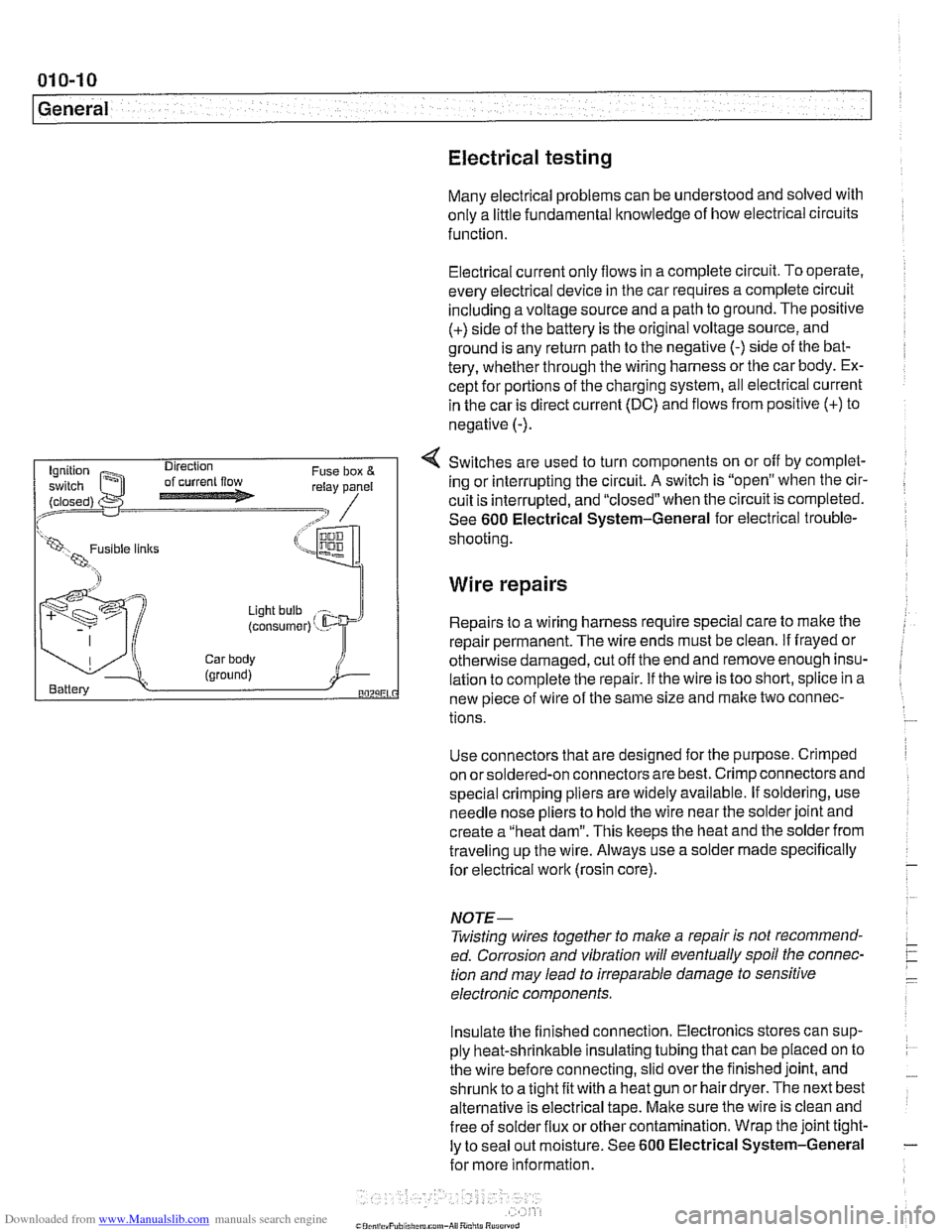
Electrical current
only flows in a complete circuit. To operate.
every electrical device in the car requires a complete circuit
including a voltage source and a path to ground. The positive
(+) side of the battery is the original voltage source, and
ground is any return path to the negative
(-) side of the bat-
tery, whether through the wiring harness or the car body. Ex-
cept for portions of the charging system, all electrical current
in the car is direct current (DC) and flows from positive
(+) to
negative
(-).
4 Switches are used to turn components on or off by complet-
ing or interrupting the circuit.
A switch is "open" when the cir-
cuit is interrupted, and "closed" when the circuit is completed.
See
600 Electrical System-General for electrical trouble-
(LW, 1 shooting
Wire repairs
Light bulb
(consumer) ' - Repairs to a wiring harness require special care to make the
repair permanent. The wire ends must be clean.
if frayed or
Car body otherwise damaged, cut off the end and remove enough insu- (ground) i Battery lation to complete the repair. if the wire is too short, splice in a BOZLiEL new piece of wire of the same size and make two connec-
tions.
Use connectors that are designed for the purpose. Crimped
on orsoldered-on connectors are best. Crimp connectors and
special crimping pliers are widely available. If soldering, use
needle nose pliers to hold the wire near the solder joint and
create a "heat dam". This keeps the heat and the solder from
traveling up the wire. Always use a solder made specifically
for electrical
work (rosin core).
NOJE-
Twisting wires together to make a repair is not recommend-
ed. Corrosion and vibration will eventually spoil the connec-
tion and may lead to irreparable damage to sensitive
electronic components.
Insulate the finished connection. Electronics stores can sup-
ply heat-shrinkable insulating tubing that can be placed on to
the wire before connecting, slid over the finished joint, and
shrunic to a tight fit with a heat gun or hair dryer. The next best
alternative is electrical tape. Make sure the wire is clean and
free of
solder flux or other contamination. Wrap the joint tight-
ly to seal out moisture. See
600 Electrical System-General
for more information.
Page 25 of 1002
Downloaded from www.Manualslib.com manuals search engine
Sockets Socltets are used with a ratchet handle for speed and conve-
nience and can be combined with extensions and universal
joints (swivels) to reach fasteners more easily. The most
common socket drive sizes are
114 inch, 318 inch and 112 inch.
Sockets come in
6 point and 12 point styles. The 6 point offers
a better grip on tight nuts and bolts.
6 mm to 19 mm socltets
are the most needed sizes. Below is a list of typical bolt
diarn-
eters and the corresponding wrench sizes.
Common bolt diameters and wrench sizes
M5 8 rnrn
M6
10 rnm
M8 12rnrnor13rnrn
MI 0 17 rnrn
MI2 19 rnrn
M14 22 mm
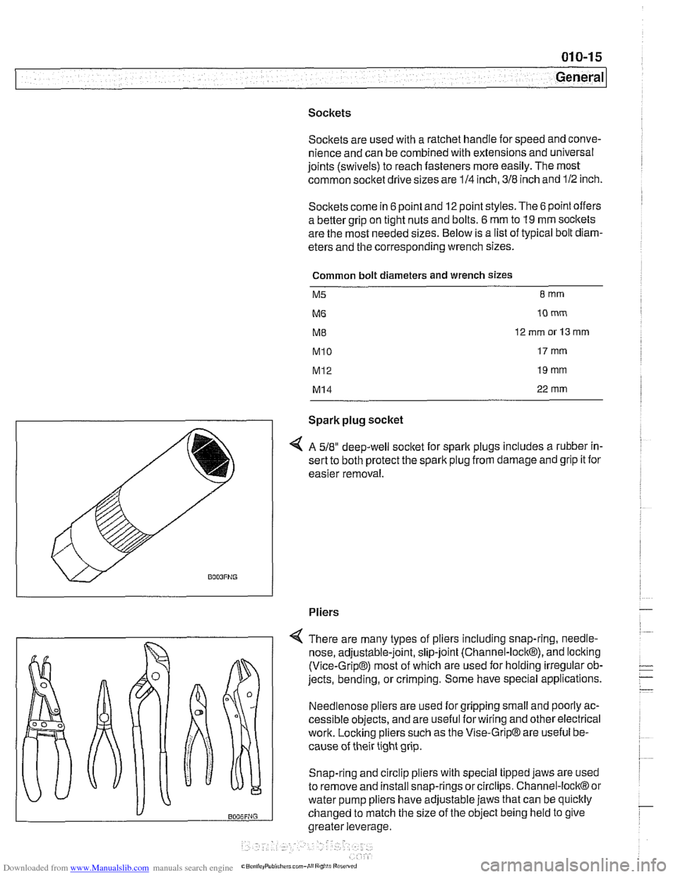
Spark plug socket
4 A 518" deep-well socket for sparlt plugs includes a rubber in-
sert to both protect the spark plug from damage and grip it for
easier removal.
Pliers
There are many types of pliers including snap-ring,
needle-
nose, adjustable-joint, slip-joint (Channel-lock@), and locking
(Vice-Grip@) most of which are used for holding irregular ob-
jects, bending, or crimping. Some have special applications.
Needlenose pliers are used for gripping small and poorly ac-
cessible objects, and are useful forwiring and other electrical
work. Locking pliers such as the Vise-Grip@ are useful be-
cause of their tight grip.
Snap-ring and circlip pliers with special tipped jaws are used
to remove and install snap-rings or circlips. Channel-lock@ or
water pump pliers have adjustable jaws that can be quicltly
changed to match the size of the object being held to give
greater leverage,
Page 71 of 1002
Downloaded from www.Manualslib.com manuals search engine
Two common causes of driveability problems are incorrect
system voltage and bad grounds.
System voltage
Digital motor electronics (DME) requires that the system (bat-
tery) voltage be maintained within a narrow range of DC volt-
age.
DC voltage levels beyond or below the operating range,
or any
AIC voltage in the electrical system can cause havoc.
When troubleshooting an illuminated MIL, make sure the bat-
tery is fully charged and capable of delivering all its power to
the electrical system. An undercharged battery can amplify
AIC alternator output ripple.
To
make a quick check of the battery charge, measure the
voltage across the battery terminals with all cables attached
and the ignition off.
Afully charged battery will measure 12.6
volts or slightly more, compared to 12.1 5 volts for a battery
with a 25% charge.
The DME system operates at low voltage and current levels,
making it sensitive to small increases in resistance. The elec-
trical system is routinely subjected to corrosion, vibration and
wear, so faults or corrosion in the wiring harness and connec-
tors are not uncommon. Check the battery terminals
forcorro-
sion or loose cable connections. See 121 Battery, Starter,
Alternator for additional information.
If a battery cable connection has no
v~sible faults but is still
suspect, measure the voltage drop across the connection. A
large drop indicates excessive resistance, meaning that the
connection is corroded, dirty, or damaged. Clean or repairthe
connection and retest.
NOTE-
For instructions on conducting a voltage drop test and other
general electrical troubleshooting information, see
600 Elec-
trical System-General.
Visually inspect all wiring, connectors, switches and fuses in
the system. Loose or damaged connectors can cause inter-
mittent problems, especially the small terminals in the ECM
connectors. Disconnect the wiring harness connectors to
check for corrosion, and use electrical cleaning spray to re-
move contaminants.
Main grounds
Good grounds are critical to proper DME operation. If a
ground connection has no visible faults but is still suspect.
measure the voltage drop across the connection. A large volt-
age drop means high resistance. Clean or repair the connec-
tion and retest.
LBuntr.yP~sbhnllcn.can#-AII A,~iltl Rcsrwsd
Page 80 of 1002
Downloaded from www.Manualslib.com manuals search engine
110-8
1 Engine Removal and Installation
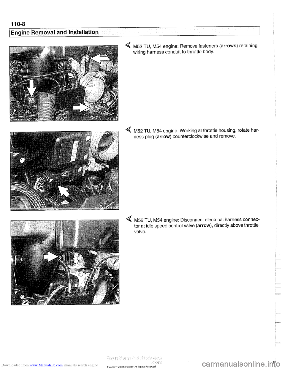
4 M52 TU, M54 engine: Remove fasteners (arrows) retaining
wiring harness conduit to throttle body.
4 M52 TU, M54 engine: Working at throttle housing, rotate har-
ness plug (arrow) counterclockwise and remove.
4 M52 TU, M54 engine: Disconnect electrical harness connec-
tor at idle speed control valve (arrow), directly above throttle
valve.
Page 86 of 1002
Downloaded from www.Manualslib.com manuals search engine
110-14
I Engine Removal and Installation
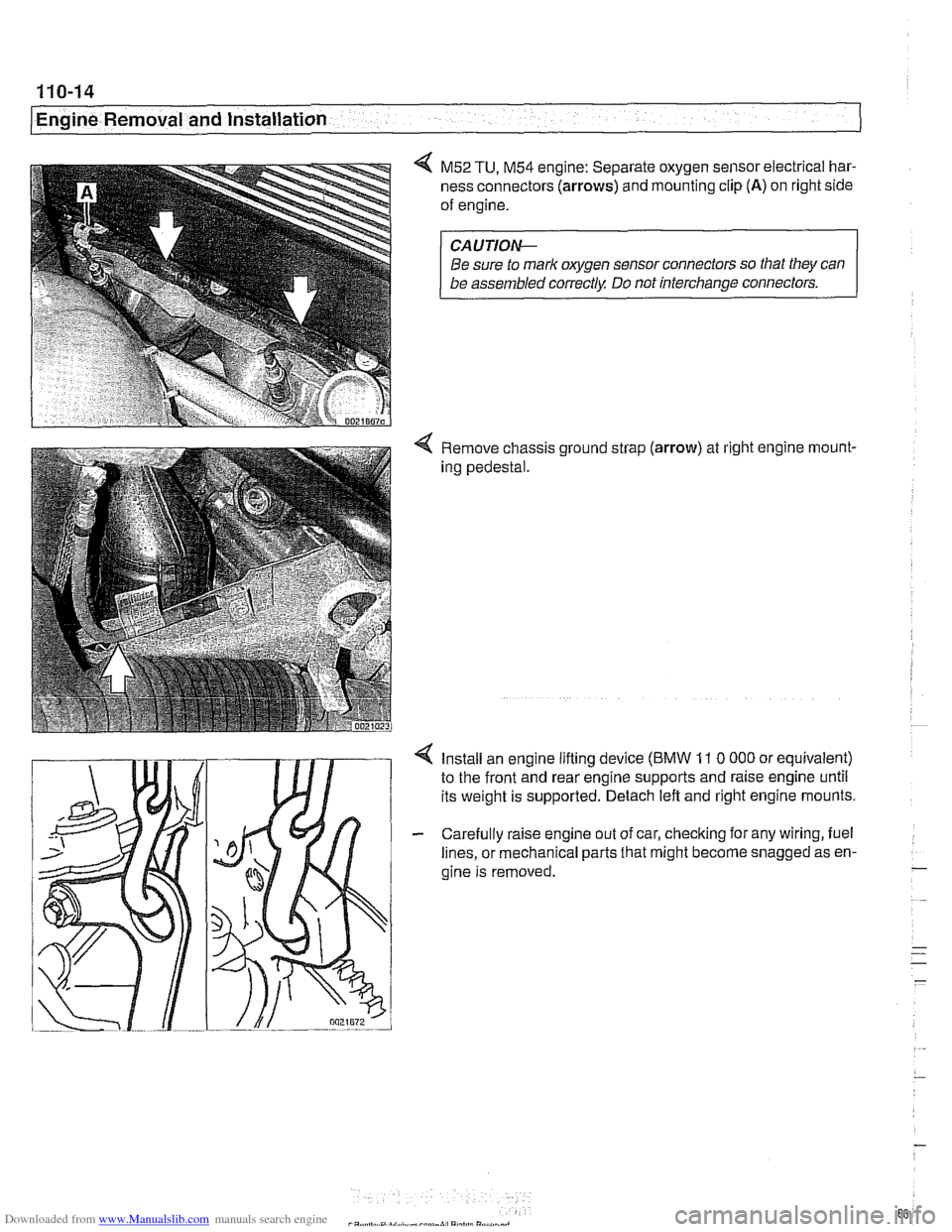
4 M52 TU, M54 engine: Separate oxygen sensor electrical har-
ness connectors
(arrows) and mounting clip (A) on right side
of engine.
CA UTIOW
Be sure to mark oxygen sensor connectors so that they can
be assembled correctly Do not interchange connectors.
4 Remove chassis ground strap (arrow) at right engine rnount-
ing pedestal.
4 Install an engine lifting device (BMW 11 0 000 or equivalent)
to the front and rear engine supports and raise engine until
its weight is supported. Detach left and right engine mounts.
- Carefully raise engine out of car, checking for any wiring, fuel
lines, or mechanical parts that might become snagged as en-
gine is removed.
-
. ..
- .- -
-
Page 89 of 1002
Downloaded from www.Manualslib.com manuals search engine
- .. -.
-. Engine Removal and in=/
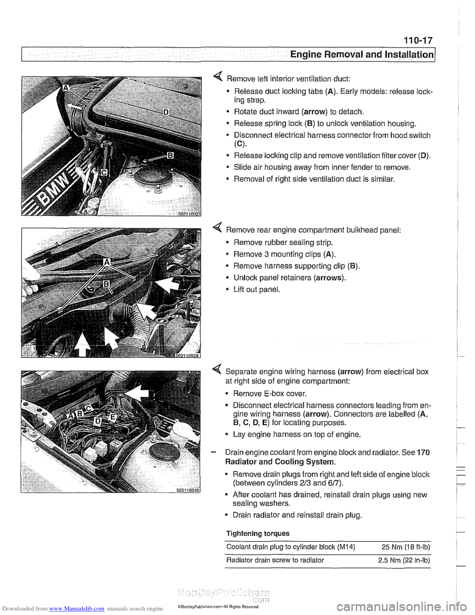
4 Remove left interior ventilation duct:
Release duct locking tabs (A). Early models: release
loclc
ing strap.
* Rotate duct inward (arrow) to detach.
Release spring
loclc (El) to unlock ventilation housing.
Disconnect electrical harness connector from hood switch
(C).
Release locking clip and remove ventilation filter cover (D).
Slide air housing away from inner fender to remove.
Removal
of right side ventilation duct is similar.
4 Remove rear engine compartment bulkhead panel:
Remove rubber sealing strip.
* Remove 3 mounting clips (A).
Remove harness supporting clip
(El).
Unlock panel retainers (arrows).
Lifl out panel.
< Separate engine wiring harness (arrow) from electrical box
at right side of engine compartment:
Remove E-box cover.
Disconnect electrical harness connectors leading from en-
gine wiring harness (arrow). Connectors are labelled (A,
El, C. D, E) for locating purposes.
Lay engine harness on top of engine.
- Drain engine coolant from engine block and radiator. See 170
Radiator and Cooling System.
Remove drain plugs from right and left side of engine
bloclc
(between cylinders 213 and 617).
Afler coolant has drained, reinstall drain plugs using new
sealing washers.
Drain radiator and reinstall drain plug.
Tightening
torques
Coolant drain plug to cylinder block (M14) 25 Nm (18 ft-ib)
Radiator drain screw to radiator 2.5
Nm (22 in-lb)
Page 119 of 1002
Downloaded from www.Manualslib.com manuals search engine
11 3-25
Cylinder Head Removal and Installation
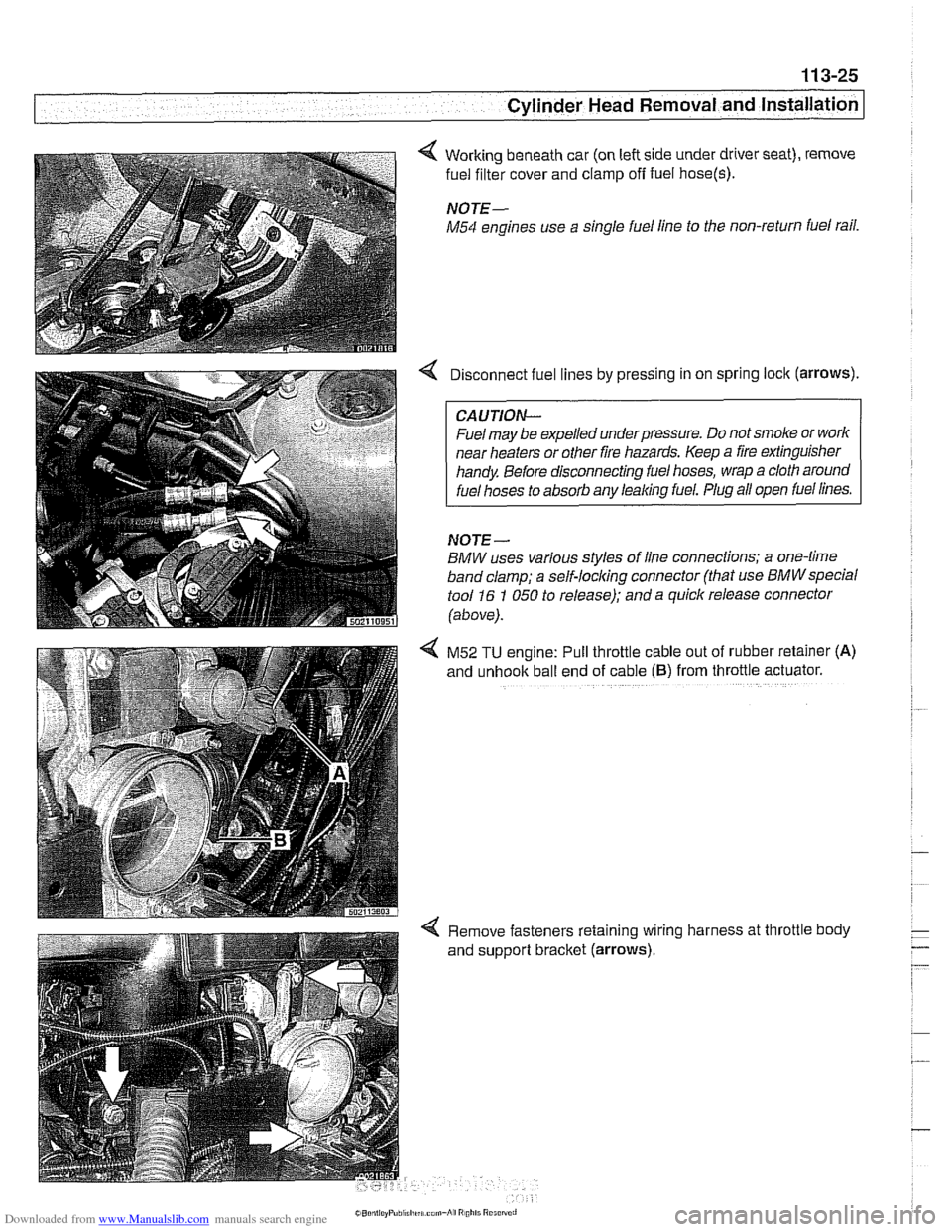
4 Working beneath car (on left side under driver seat), remove
fuel filter cover and clamp
off fuel hose(s).
NOTE-
M54 engines use a single fuel line to the non-return fuel rail.
Disconnect fuel lines by pressing in on spring lock (arrows).
CAUTION--
Fuel may be expelled underpressure. Do not smoke or worlc
near heaters or other fire hazards. Keep a fire extinguisher
handy Before disconnecting fuel hoses, wrap a cloth around
fuel hoses to absorb any leaking fuel. Plug all open fuel lines.
NOJE-
BMW uses various styles of line connections; a one-time
band clamp; a
self-locl(ing connector (that use BMWspecial
tool 16 1 050 to release); and a quick release connector
(above).
4 M52 TU engine: Pull throttle cable out of rubber retainer (A)
and unhook ball end of cable (6) from throttle actuator.
4 Remove fasteners retaining wiring harness at throttle body
and support bracket (arrows).