ignition coil BMW 540i 2001 E39 User Guide
[x] Cancel search | Manufacturer: BMW, Model Year: 2001, Model line: 540i, Model: BMW 540i 2001 E39Pages: 1002
Page 167 of 1002
Downloaded from www.Manualslib.com manuals search engine
11 3-73
Cylinder Head Removal and Installation /
1
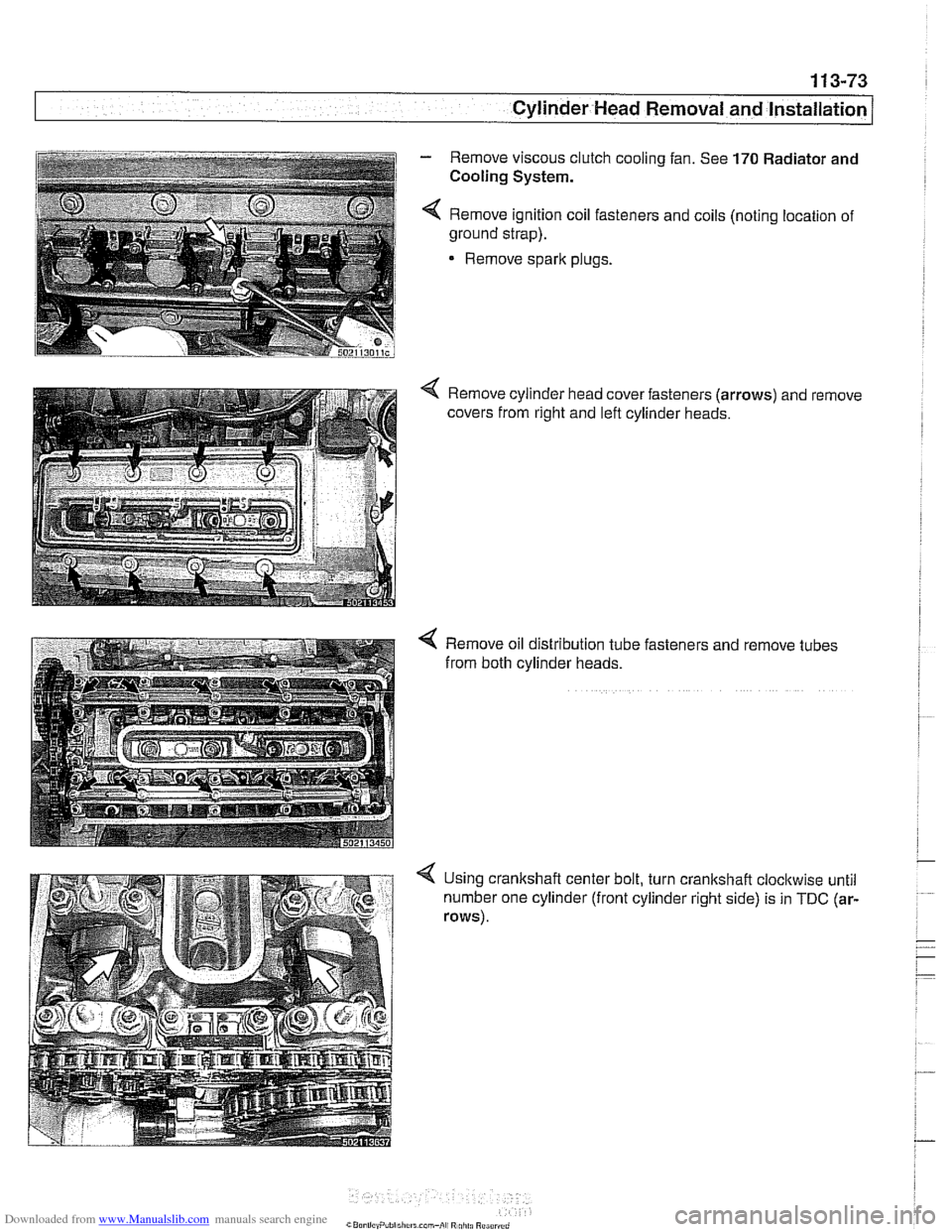
- Remove viscous clutch cooling fan. See 170 Radiator and
i Cooling System. i i I 4 Remove ignition coil fasteners and coils (noting location of
~ ground strap).
1
Remove sparlc plugs.
i
Remove oil distribution tube fasteners and remove tubes
from both cylinder heads.
4 Using crankshaft center bolt, turn crankshaft cloclcwise until
number one cylinder (front cylinder right side) is in
TDC (ar-
rows).
Page 185 of 1002
Downloaded from www.Manualslib.com manuals search engine
11 6-9
Cvlinder Head and valvetrain1
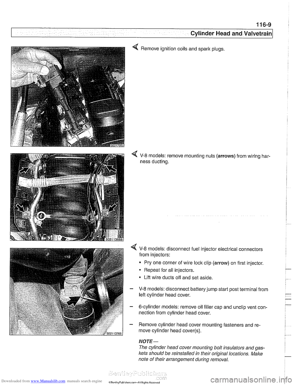
4 Remove ignition coils and spark plugs.
V-8 models: remove mounting nuts (arrows) from wiring har-
ness ducting.
< V-8 models: disconnect fuel injector electrical connectors
from injectors:
Pry one corner of wire
loclc clip (arrow) on first injector.
Repeat for all injectors.
Lift wire ducts off and set aside.
- V-8 models: disconnect battery jump start post terminal from
left cylinder head cover.
- 6-cylinder models: remove oil filler cap and unclip vent con-
nection from cylinder head cover.
- Remove cylinder head cover mounting fasteners and re-
move cylinder head cover(~).
NOTE-
The cylinder head cover mounting bolt insulators and gas-
Icets should be reinstalled in their original locations. Make
note of their arrangement
during removal.
Page 187 of 1002
Downloaded from www.Manualslib.com manuals search engine
Cylinder Head and Valvetrain
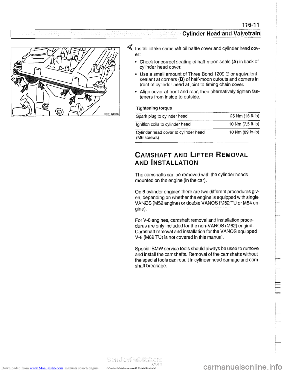
4 Install intake camshaft oil baffle cover and cylinder head cov-
er:
= Checlc for correct seating of half-moon seals (A) in back of
cylinder head cover.
Use a small amount of Three Bond 1209
@or equivalent
sealant at corners
(B) of half-moon cutouts and corners in
front of cylinder head at joint to timing chain cover.
Align cover at front and rear, then alternatively tighten fas-
teners from inside to outside.
Tightening torque
Sparic plug to cylinder head 25 Nm (18 it-lb)
Ignition coils to cylinder head 10 Nrn (7.5 ft-lb)
Cylinder head cover to cylinder iiead 10 Nrn (89 in-lb)
fM6 screws)
CAMSHAFT AND LIFTER REMOVAL
AND ~NSTALLATION
The camshafts can be removed with the cylinder heads
mounted on the engine (in the car).
On 6-cylinder engines there are two different procedures giv-
en, depending on whether the engine is equipped with single
VANOS (M52 engine) or double VANOS
(M52TU or M54 en-
gine).
For V-8 engines, camshaft removal and installation proce-
dures are
only included for the non-VANOS (M62) engine.
Camshaft removal and installation for the
VANOS eq;ipped
V-8 (M62TU) is not covered in this manual.
Special BMW service tools should always be used to remove
and install the camshafts. Removal of the camshafts without
the special tools can result in cylinder head damage and cam-
shaft breakage.
Page 214 of 1002
Downloaded from www.Manualslib.com manuals search engine
I Cylinder Head and Valvetrain
- Remove adjustable primary timing chain tensioner tool and
reinstall primary chain tensioner cylinder to cylinder head.
Tightening torque
Primary chain tensioner cylinder
to 70 Nm (52 ft-lb)
cylinder head
- Remove flywheel locking tool from crankcase. Replace spe-
cial tool bore sealing plug.
- Remove camshaft locking tools from cylinder head
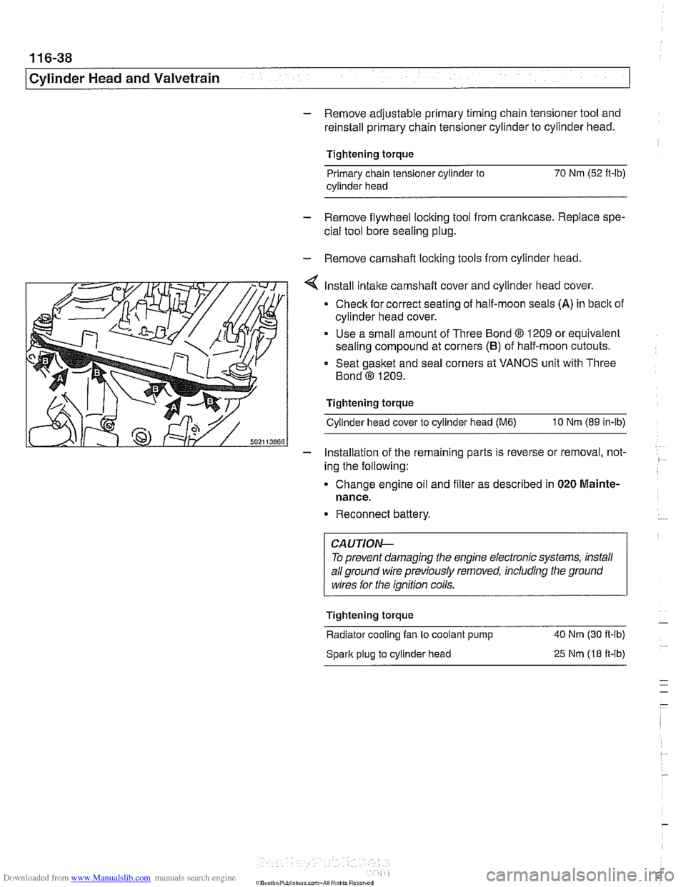
Install intake camshaft cover and cylinder head cover.
Check for correct seating of half-moon seals (A) in back of
cylinder head cover.
Use a small amount of Three Bond
8 1209 or equivalent
sealing compound at corners
(B) of half-moon cutouts.
Seat gasket and seal corners at VANOS unit with Three
Bond
@ 1209.
Tightening torque Cylinder head cover to cylinder head
(M6) 10 Nm (89 in-lb)
- Installation of the remaininq parts is reverse or removal, not- -
ing the following:
Change engine
011 and f~lter as descr~bed in 020 Mainte-
nance.
Reconnect battery.
To prevent damaging the engine electronic systems, install
all ground wire previously removed, including the ground
wires for the ignition coils.
Tightening torque
-
Radiator cooling fan to coolant pump 40 Nm
(30 ft-ib)
Spark plug to cylinder head
25 Nm (18 ft-ib)
Page 216 of 1002
Downloaded from www.Manualslib.com manuals search engine
-. .
Cylinder Head and Valvetrain -- v . -- --- --
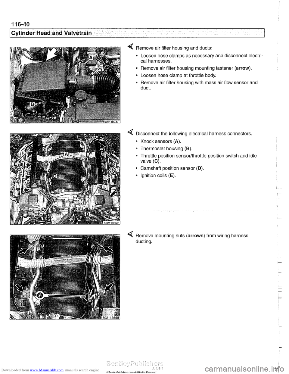
4 Remove air filter housing and ducts:
Loosen hose clamps as necessary and disconnect electri-
cal harnesses.
- Remove air filter housing mounting fastener (arrow).
Loosen hose clamp at throttle body.
Remove air filter housing with mass air flow sensor and
duct.
Disconnect the following electrical harness connectors.
Knoclc sensors (A).
Thermostat housing (B).
Throttle position sensor/throttle position switch and idle
valve
(C).
Camshaft position sensor (D).
* Ignition coils (E).
Remove mounting nuts (arrows)
ducting. from
wiring harness
Page 217 of 1002
Downloaded from www.Manualslib.com manuals search engine
Cylinder Head and Valvetrain
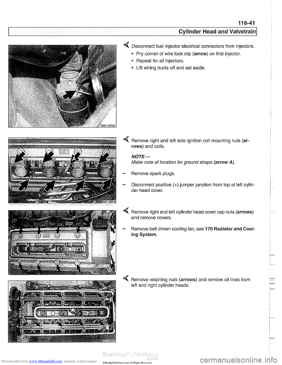
< Disconnect fuel injector electrical connectors from injectors.
Pry corner of wire lock clip (arrow) on first injector.
* Repeat for all injectors.
Lift wiring ducts off and set aside.
4 Remove right and left side ignition coil mounting nuts (ar-
rows) and coils.
NOTE-
Male note of location for ground straps (arrow A).
- Remove spark plugs.
- Disconnect positive (+)jumper junction from top of lefl cylin-
der head cover.
4 Remove retaining nuts (arrows) and remove oil lines from
left and right cylinder heads.
Page 251 of 1002
Downloaded from www.Manualslib.com manuals search engine
Camshaft Timina chain1
- Remove viscous clutch cooling fan. See 170 Radiator and
Cooling
System.
CA UTlOEIC
The radiator cooling fan nut (32mm wrench) has left- hand
threads.
.
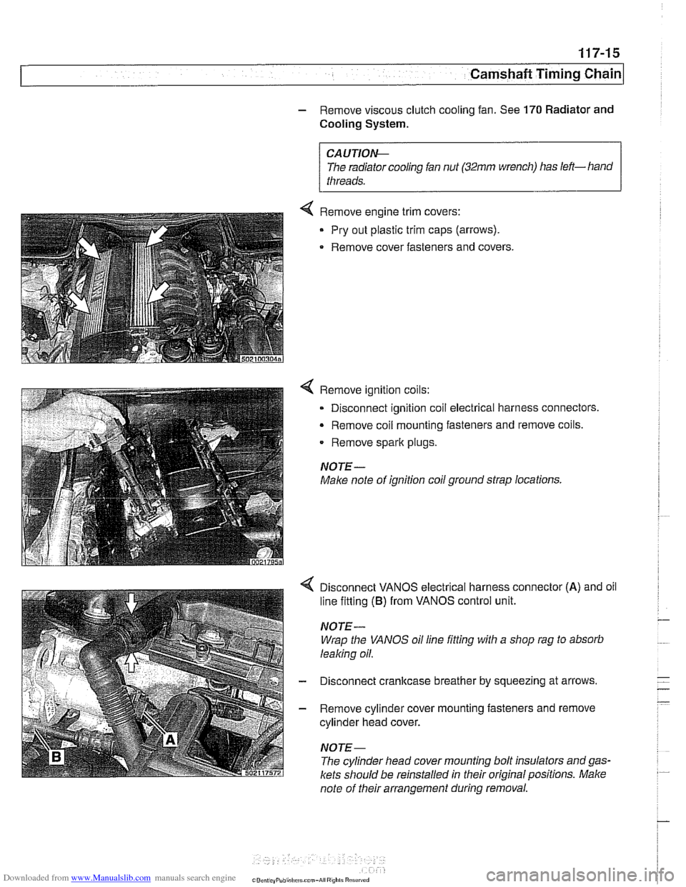
< Remove engine trim covers:
Pry out plastic trim caps (arrows).
. Remove cover fasteners and covers.
4 Remove ignition coils:
0 Disconnect ignition coil electrical harness connectors
Remove
coil mounting fasteners and remove coils.
Remove spark plugs.
NOTE-
Make note of ignition coil ground strap locations.
Disconnect VANOS electrical harness connector
(A) and oil
line fitting
(B) from VANOS control unit.
NOTE-
Wrap the VANOS oil line fitting with a shop rag to absorb
leaking oil.
- Disconnect cranltcase breather by squeezing at arrows,
- Remove cylinder cover mounting fasteners and remove
cylinder head cover.
NOTE-
The cylinder head cover mounting bolt insulators and gas.
kets should be reinstalled in their original positions. Make
note of their arrangement during removal.
Page 258 of 1002
Downloaded from www.Manualslib.com manuals search engine
Camshaft Timing Chain
VANOS timing, checking and adjusting
(M52 engine)
NOTE-
* Special BMW service tools are required to remove and in-
stall the VANOS control unit. Read the procedure through
before starting the job.
If the camshafts are not properly timed, the pistons can
contact the valves.
- Disconnect negative (-) cable from battery.
CAUTIOG Disconnecting the battery may erase
faultcode(s) storedin
control module memory. Prior to disconnecting the battery,
checlc for fault codes using special BMW diagnostic equip-
ment.
Prior to disconnecting the battery, read the battery dis-
connection cautions given in
001 General Cautions
and Warnings.
- Remove viscous clutch cooling fan. See 170 Radiator and
Cooling
System.
CAUTIOG The radiator cooling fan nut
(32 mm wrench) has left-hand
threads.
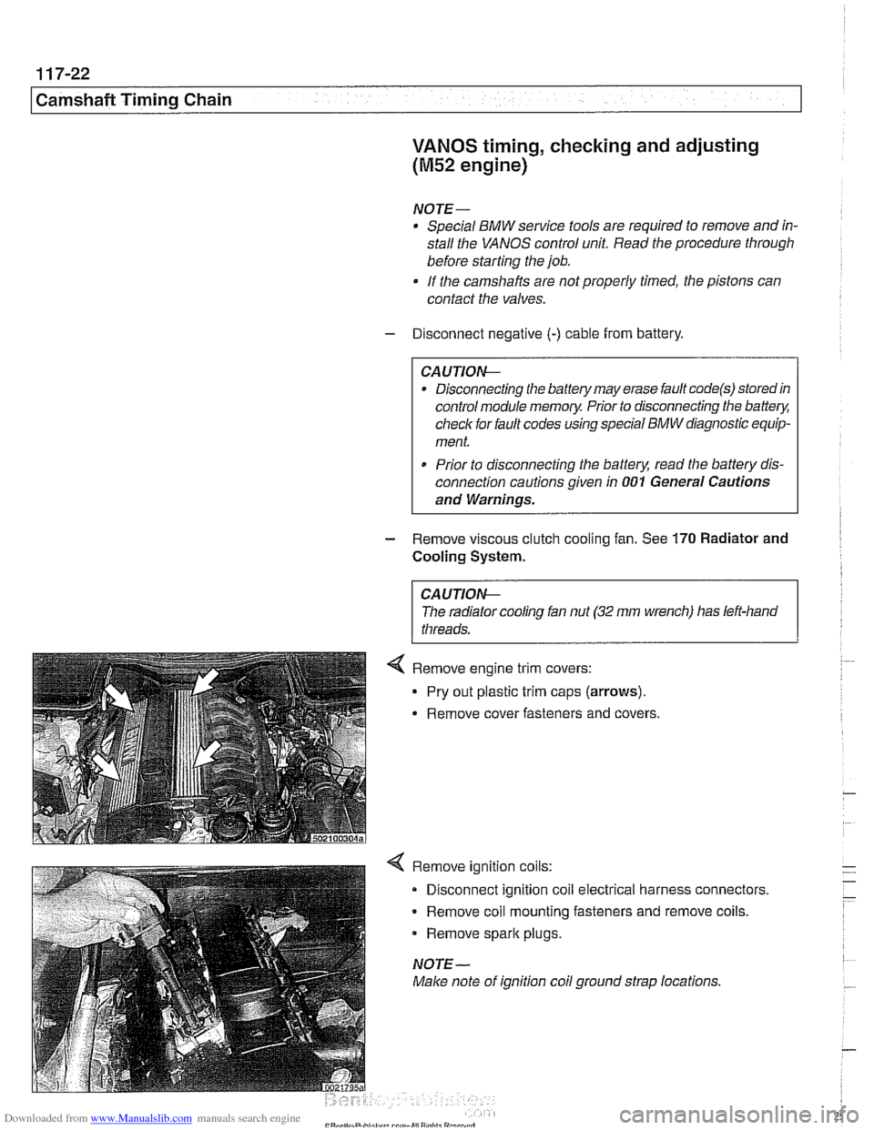
4 Remove ignition coils:
Disconnect ignition coil electrical harness connectors.
Remove coil mounting fasteners and remove coils.
Remove
spark plugs.
NOTE-
Make note of ignition coil ground strap locations.
Page 273 of 1002
Downloaded from www.Manualslib.com manuals search engine
Camshaft Timing Chain
VANOS control unit, removing
(M52 TU and M54 engines)
This procedure includes removal of the Double VANOS con-
trol unit.
NOTE-
If the Double VANOS control unit is being replaced, camshaft
timing must be checked. This procedure requires multiple
special tools. Be sure to read the procedures through before
beginning the repair.
- Working inside luggage compartment, disconnect negative
(-) battery cable.
Prior to disconnecting the
batteg read the battery discon-
nection cautions given in
001 General Cautions and
Remove engine cooling fan assembly. See 170 Radiator
and Cooling System.
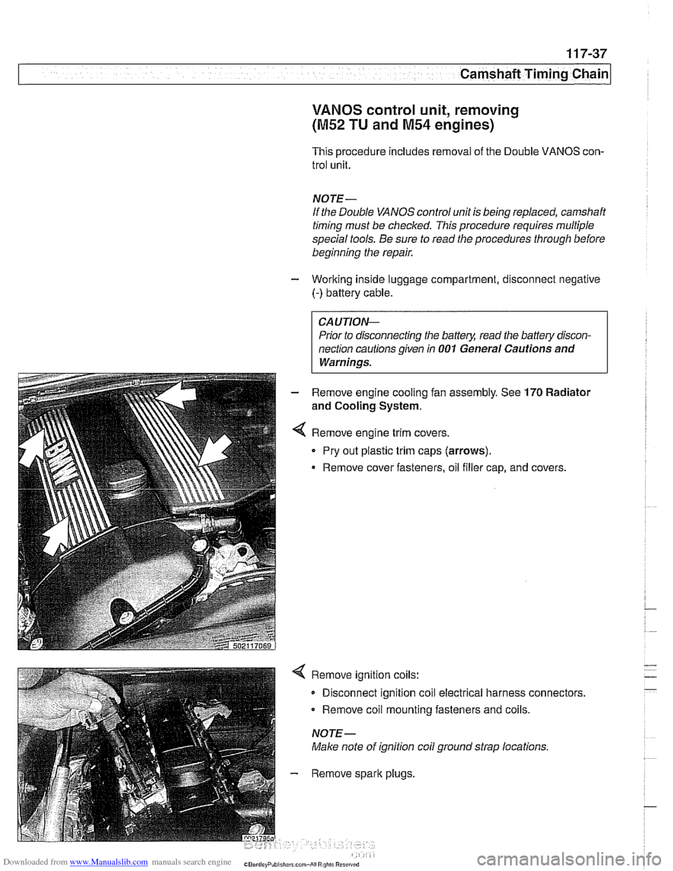
Remove engine trim covers.
Pry out plastic trim caps (arrows).
Remove cover fasteners, oil filler cap, and covers.
Remove ignition coils:
Disconnect ignition coil electrical harness connectors.
Remove coil mounting fasteners and coils.
NOTE-
Make note of ignition coil ground strap locations.
Remove spark plugs,
Page 285 of 1002
Downloaded from www.Manualslib.com manuals search engine
-- - -- - -- Camshaft Timing chain1
- Remove camshaft locking tools from rear of camshafts
- Remove BMW special tool 11 4 220 (adjustable primary
chain tensioner). Reinstall primary chain tensioner.
Tightening torque Primary chain tensioner to cylinder head
70
Nm (52 it-lb)
- Remove crankshaft locking tool from transmission bellhous-
ing. Reinstall sealing plug.
- Remove VANOS setup bracket from front of cylinder head
- lnstall VANOS control unit as described earlier in this group.
- Remove compressed air fitting (BMW special tool 11 3 450)
from VANOS control unit.
- Fit VANOS oil line banjo bolt with new seals. Attach oil line to
VANOS control unit.
Tightening torque
Oil line to VANOS control unit (banjo bolt) 32 Nm (24 H-lb)
- Remainder of installation is reverse of removal, noting the fol-
lowing:
lnstall spark plugs.
* lnstall intake camshaft plastic baffle prior to installing cylin-
der head cover. lnstall ignition coil packs and connect elec-
trical harness connectors.
Install radiator cooling fan.
- lnstall air filter housing and top engine cover.
Tightening torque Radiator cooling fan
(VISCOUS clutch) to 40 Nm (30 ft-lb)
coolant pump
Cyitnder head cover to cylinder head 10 Nm (89 in-lb)
Sparlc plug to cylinder head 25 Nm (18 ft-lb)