timing chain BMW 540i 2001 E39 User Guide
[x] Cancel search | Manufacturer: BMW, Model Year: 2001, Model line: 540i, Model: BMW 540i 2001 E39Pages: 1002
Page 113 of 1002
Downloaded from www.Manualslib.com manuals search engine
I Cylinder Head Removal and Installation I
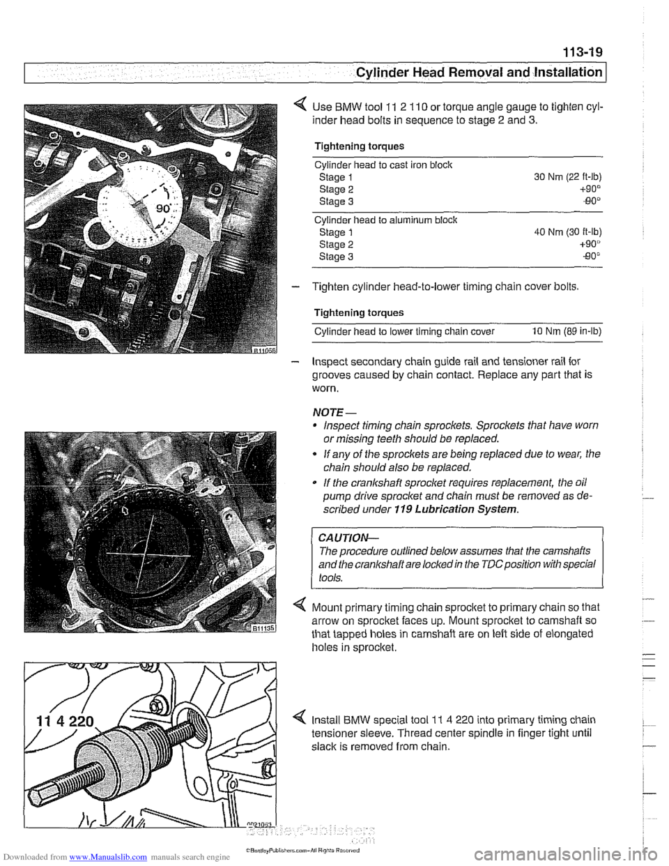
< Use BMW tool 11 2 110 or torque angle gauge to tighten cyl-
inder head bolts in sequence to stage
2 and 3.
Tightening torques
Cylinder head to cast iron
bloclc
Staoe 1
staie 2
Stage 3
Cyllnder head to aiumlnum block
Stage
1 40 Nm (30 it-lb)
Stage 2 +90°
Staoe 3 -80"
- Tighten cylinder head-to-lower timing chain cover bolts.
Tightening torques
cylinderhead to lower timing chain cover 10 Nm (89 in-lb)
- Inspect secondary chain guide rail and tensioner rail for
grooves caused by chain contact. Replace any part that is
worn.
NOTE-
Inspect timing chain sprocl(ets. Sprockets that have worn
or missing teeth should be replaced.
* If any of the sprockets are being replaced due to wear, the
chain should also be replaced.
If the crankshaft sproclet requir?s replacement, the oil
pump drive sprocket and chain must be removed as de-
scribed under
119 Lubrication System.
The procedure outlined below assumes that the camshafts
and the
cranl(shaft are locledin the TDCposition with special
4 Mount primary timing chain sprocltet to primary chain so that
arrow on sprocket faces up. Mount sprocket to camshaft so
that tapped holes in camshaft are on left side of elongated
holes in sprocltet
Install BMW special tool
1 I 4 220 into primary timing chain
tensioner sleeve. Thread center spindle in finger tight
until
slack is removed from chain.
Page 114 of 1002
Downloaded from www.Manualslib.com manuals search engine
--
Cylinder Head Removal and Installation
NOTE-
BMW special tool 11 4 220 is an adjustable primary chain
tensioner and simulates the function of the hydraulic
tensioner.
- Check that elongated holes in primary sprocket are now cen-
tered to bolt holes in camshaft and chain is free of slack. If
not, reposition sprocket to chain and reinstall.
- lnstall secondary timing chain guide and secondary chain
tensioner. Tighten mounting bolts (tensioner remains locked
down for now using
BMW special tool 11 3 292).
- Install cylinder identification trigger plate to front of intake
camshaft with studs.
- Install spacer to front of intake camshaft.
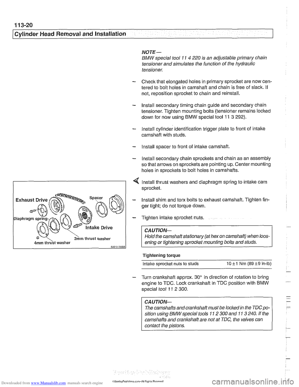
- Install secondary chain sprockets and chain as an assembly
so that arrows on sprockets are pointing up. Center mounting
holes in sprockets to bolt holes in camshafts.
4 lnstall thrust washers and diaphragm spring to intake cam
sprocket.
I 2hm thrust washer I
- Install shim and torx bolts to exhaust camshaft. Tighten fin-
ger tight; do not torque down.
- Tighten intake sprocket nuts.
CA UTIOG
Hold the camshaft stationary (at hex on camshaft) when loos-
enino or tiahtenino sorocket mounting bolts and studs.
Tightening torque
Intake s~rocket nuts to studs 10 +l Nm (89 +9 in-lb)
- Turn crankshaft approx. 30" in direction of rotation to bring
engine to TDC. Lock crankshaft in TDC position with BMW
special tool
11 2 300.
CAUTION-
The camshafts andcranlshaft must be lockedin the TDCpo-
sition using BMW special tools 11 2 300 and 11 3 240. If the
camshafts and cranl(shaft are not at TDC, the valves can
contact the pistons.
Page 115 of 1002
Downloaded from www.Manualslib.com manuals search engine
- -.
Cylinder Head Removal and lnstallation
NOTE-
Be Sure the secondary timing chain tensioner is locked down
and the exhaust
camshaif mounting bolts are loose before
proceeding.
- Install VANOS control unit. See VANOS control unit, install-
ing
(M52 engine) in 117 Camshaft Timing Chain.
CAUTION--
Incorrect installation ofthe VANOS control may result in dam-
age to the engine valvefrain.
- Install exhaust manifolds using new gaskets and nuts. Coat
manifold studs with copper paste prior to installing nuts.
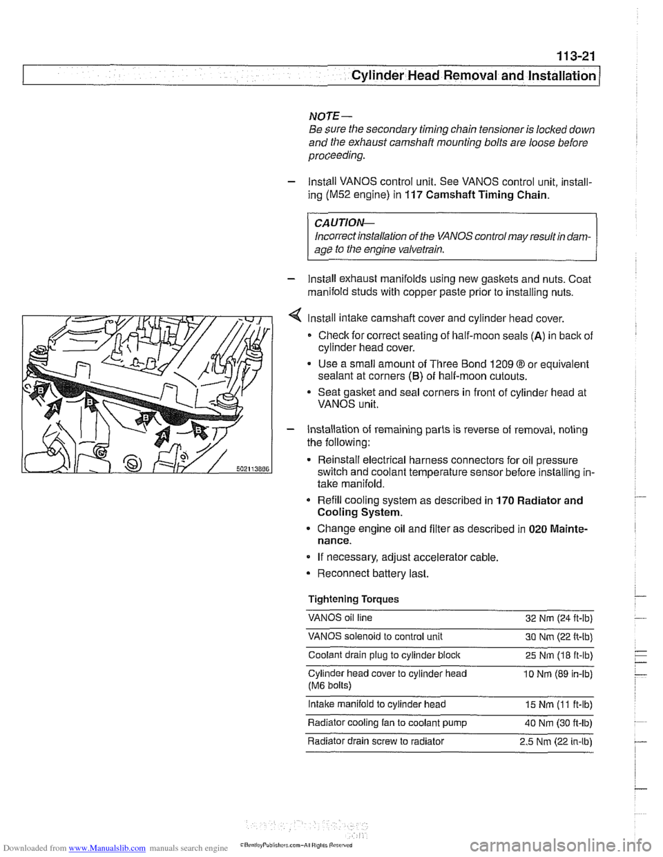
Install intake camshaft cover and cylinder
head cover.
Check for correct seating of half-moon seals
(A) in back of
cylinder head cover.
Use a small amount of Three Bond 1209
O or equivalent
sealant at corners
(6) of half-moon cutouts.
Seat gasket and seal corners in front of cylinder head at
VANOS unit.
- Installation of remaining parts is reverse of removal, noting
the following:
Reinstall electrical harness connectors for oil pressure
switch and coolant temperature sensor before installing in-
take manifold.
Refill cooling system as described in 170 Radiator and
Cooling System.
Change engine oil and filter as described in 020 Mainte-
nance.
If necessary, adjust accelerator cable.
Reconnect battery last.
Tightening Torques
VANOS oil line
32 Nm (24
ft-lb)
VANOS solenoid to control unit 30 Nm (22 ft-lb)
Coolant drain plug to cylinder
block 25 Nm (18 ft-lb)
Cylinder head cover to cylinder head
10 Nrn (89 in-lb)
(M6 bolts)
intake manifold to cylinder head 15 Nm (I 1 ft-lb)
Radiator cooling fan to coolant pump
40 Nm (30 ft-lb) - . .
Radiator drain screw to radiator 2.5 Nm (22 in-lbl
Page 127 of 1002
Downloaded from www.Manualslib.com manuals search engine
- -
-- .- Cylinder ~ead~ernoval and Installation I - -.
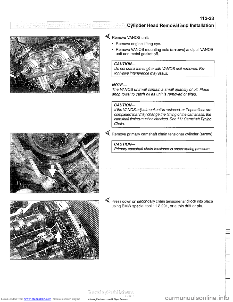
Remove VANOS unit:
Remove engine lifting eye.
- Remove VANOS mounting nuts (arrows) and pull VANOS
unit and metal gasket off.
CAUTION-
Do not crank the engine with VANOS unit removed. Pis-
tonhalve inteiference may result.
NOTE-
The VANOS unit will contain a small quantity of oil. Place
shop towel to catch oil as unit is removed or tilted.
CAUTION-
If the VANOS adjustment unit is replaced, or if operations are
completed that may change the timing of
the camshafts, the
camshaft timing must be checked. See
11 7Camshaft Timing
Chain.
4 Remove primary camshaft chain tensioner cylinder (arrow).
CAUTION-
Primary camshaft chain tensioner is under spring pressure.
Press down on secondary chain tensionerand lock into place
using
BMW special tool 11 3 291, or a thin drifl or pin.
Page 130 of 1002
Downloaded from www.Manualslib.com manuals search engine
1 13-36
Cylinder Head Removal and Installation
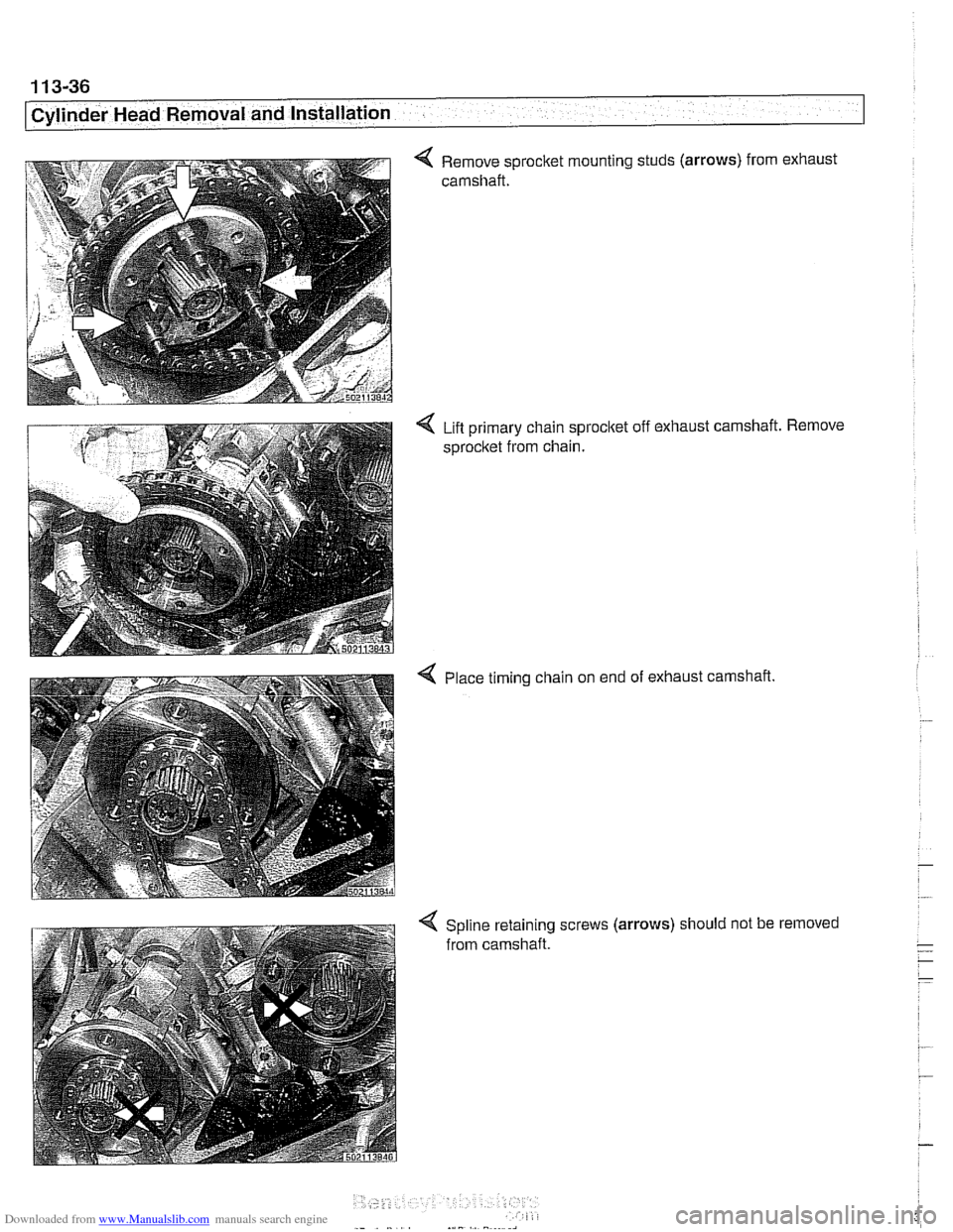
4 Remove sprocket mounting studs (arrows) from exhaust
camshaft.
Lift primary chain sprocltet off exhaust camshaft.
sprocket from chain.
4 Place timing chain on end of exhaust camshaft Remove
4 Spline retaining screws (arrows) should
not be removed
from camshaft.
Page 133 of 1002
Downloaded from www.Manualslib.com manuals search engine
. - -- -
Cylinder Head Removal and Installation --
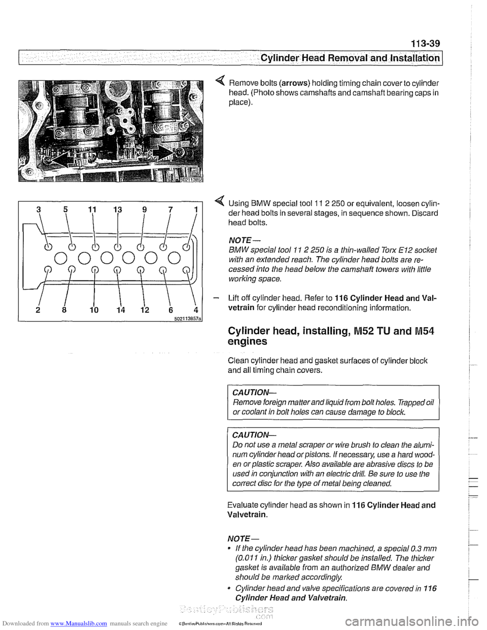
Remove bolts (arrows) holding timing chain cover to cylinder
head. (Photo shows camshafts and camshaft bearing caps in
place).
4 Using BMW special tool 11 2 250 or equivalent, loosen cylin-
der head bolts in several stages, in sequence shown. Discard
head bolts.
NOJE-
BMW special tool 11 2 250 is a thin-walled Torx El2 socket
with an extended reach. The cylinder head bolts are re-
cessed into the head below the
camshaft towers with little
working space.
- Lift off cylinder head. Refer to 116 Cylinder Head and Val-
vetrain for cylinder head reconditioning information.
Cylinder head, installing, M52 TU and M54
engines
Clean cylinder head and gasket surfaces of cylinder bloclc
and all timing chain covers.
CAUTION- Remove foreign matter and liquid from bolt holes. Trapped oil
or coolant in bolt holes can cause damage to
blocl~,
CAUJION-
Do not use a metal scraper or wire brush to clean the alumi-
num cylinder head or pistons. If necessary, use a hard wood-
en orplastic scraper. Also available are abrasive discs to be
used in conjunction with an electric drill. Be sure to use the
correct disc for the type of metal being cleaned.
Evaluate cylinder head as shown in
116 Cylinder Head and
Valvetrain.
NOTE- If the cylinder head has been machined, a special 0.3
mm
(0.01 1 in.) thicker gasket should be installed. The thicker
gasket is available from an authorized
BMW dealer and
should be marked accordingly
Cylinder head and valve specifications are covered in 116
Cylinder Head and Valvetrain.
Page 134 of 1002
Downloaded from www.Manualslib.com manuals search engine
11 3-40
I Cylinder Head Removal and Installation
Lubricate camshafts, camshaft carriers, bearing caps, hy-
draulic lifters, friction washers, splined shafts and spline hubs
with assembly lubricant before installation.
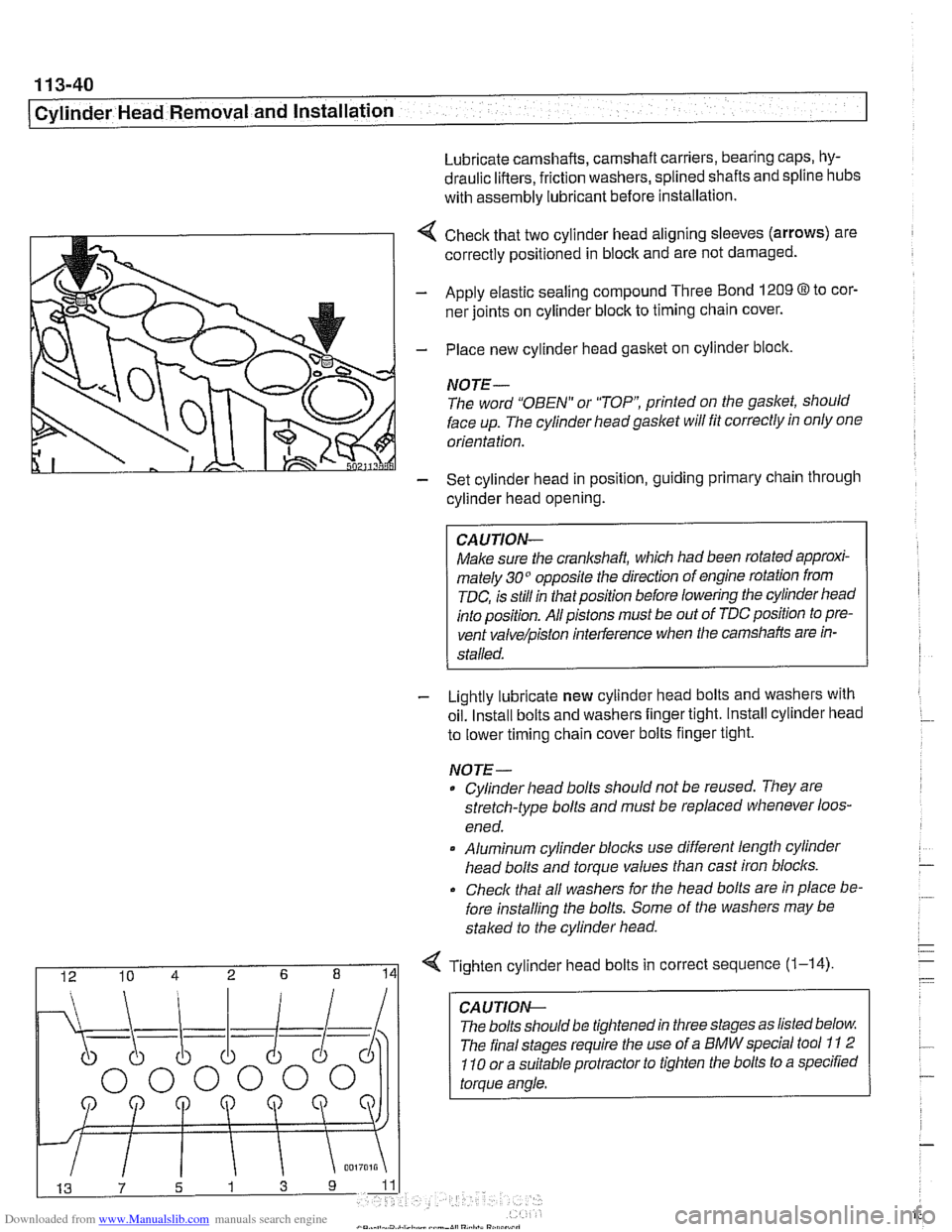
4 Check that two cylinder head aligning sleeves (arrows) are
correctly positioned in block and are not damaged.
- Apply elastic sealing compound Three Bond 1209 8 to cor-
ner joints on cylinder block to timing chain cover.
- Place new cylinder head gasket on cylinder block.
NOTE-
The word "OBEN" or "TOP printed on the gasket, should
face up. The cylinder headgaslet will fit correctly in only one
orientation.
- Set cylinder head in position, guiding primary chain through
cylinder head opening.
CAUJION-
Make sure the crankshaft, which had been rotated approxi-
mately 30" opposite the direction of engine rotation from
TDC, is still in thatposition before lowering the cylinder head
into position. All pistons must be out of TDC position to pre-
vent
valve/piston interference when the camshafts are in-
stalled.
- Lightly lubricate new cylinder head bolts and washers with
oil. Install bolts and washers finger tight. Install cylinder head
to lower timing chain cover bolts finger tight.
NOJE-
Cylinder head bolts should not be reused. They are
stretch-type bolts and must be replaced whenever loos-
ened.
* Aluminum cylinder blocls use different length cylinder
head bolts and torque values than cast iron blocks.
Check that all washers for
Nle head bolts are in place be-
fore installing the bolts. Some of the washers may be
staked to the cylinder head.
I 12 10 4 2 6 8 141 Tighten cylinder head bolts in correct sequence (1-14)
CA U TIOW-
The bolts should be tightened in three stages as listed below
The final stages require the use of a BMW special tool
11 2
110 or a suitable protractor to tighten the bolts to a specified
torque angle.
Page 135 of 1002
![BMW 540i 2001 E39 User Guide Downloaded from www.Manualslib.com manuals search engine
. - ..
Cylinder Head Removal and installation] --
- Secure cylinder head bolts by torquing an additional 90"
each for Stage 2 and 3.
T BMW 540i 2001 E39 User Guide Downloaded from www.Manualslib.com manuals search engine
. - ..
Cylinder Head Removal and installation] --
- Secure cylinder head bolts by torquing an additional 90"
each for Stage 2 and 3.
T](/img/1/2822/w960_2822-134.png)
Downloaded from www.Manualslib.com manuals search engine
. - ..
Cylinder Head Removal and installation] --
- Secure cylinder head bolts by torquing an additional 90"
each for Stage 2 and 3.
Tightening torques
Cylinder head to engine block
(aluminum block)
Stage
1 40 Nm (30 it-lb)
Stage 2 +90°
Stage 3 80'
4 lnstall intake camshaft position sensor (arrow).
4 Install lower secondary chain guide. Tighten tom bolts to
specifications. The bolt on the intake camshaft side is long
and extends into the engine block.
4 Install and tighten cylinder head-to-lower timing chain cover
bolts (arrows). (Photo shows camshafts in place).
Tightening torque Secondary chain guide to cylinder head
10 Nm (89 in-lb)
Cylinder head to lower timing chain cover
M6 10 Nm (89 in-lb)
M7 15 Nm (1 1 it-lb)
Page 136 of 1002
Downloaded from www.Manualslib.com manuals search engine
1 13-42
I Cylinder Head Removal and Installation
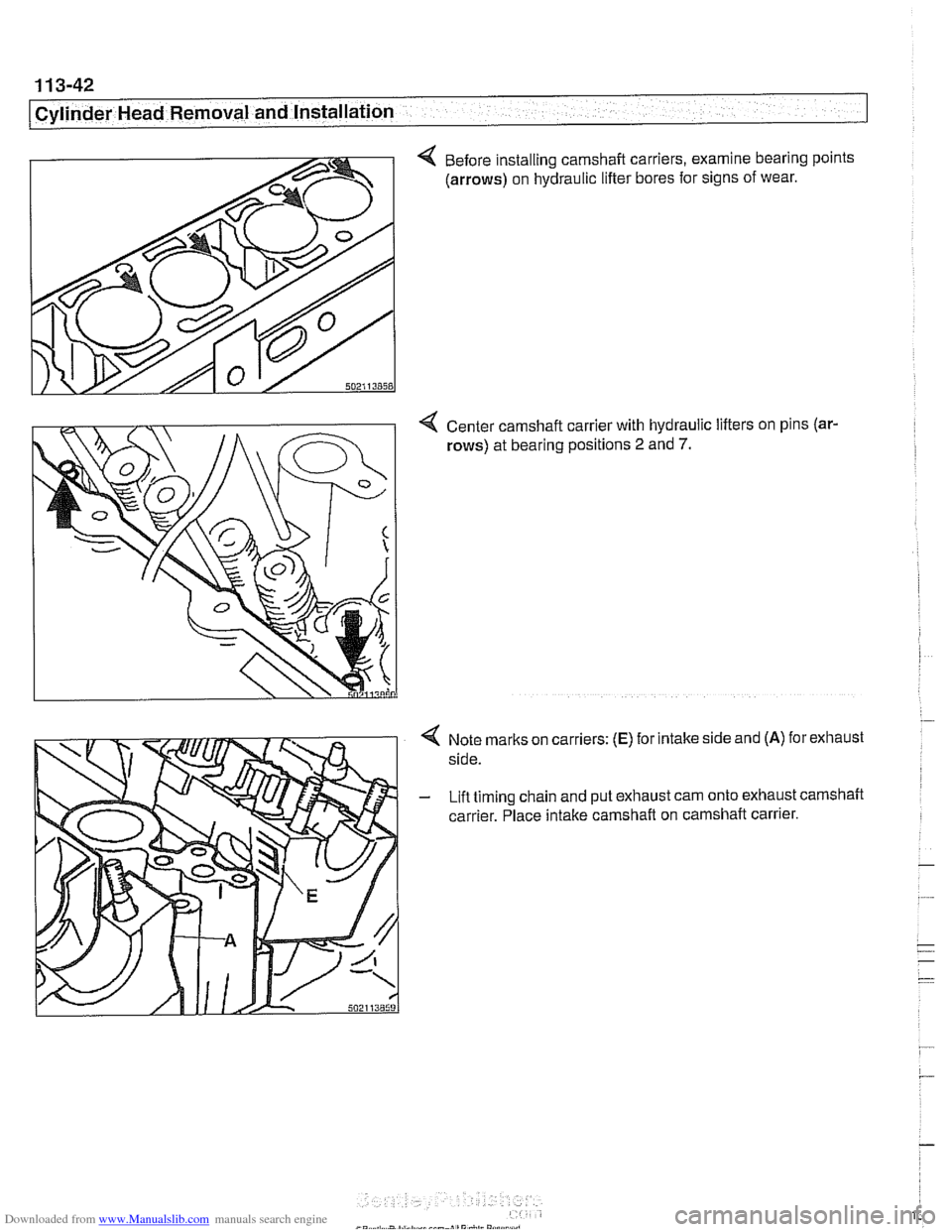
4 Before installing camshaft carriers, examine bearing points
(arrows) on hydraulic lifter bores for signs of wear.
4 Center camshaft carrier with hydraulic lifters on pins (ar-
rows) at bearing positions 2 and 7.
Note marks on carriers: (E) for intake side and (A) for exhaust
side.
Lift timing chain and put exhaust cam onto exhaust camshaft
carrier. Place intake camshaft on camshaft carrier.
Page 138 of 1002
Downloaded from www.Manualslib.com manuals search engine
11 3-44
I Cylinder Head Removal and Installation
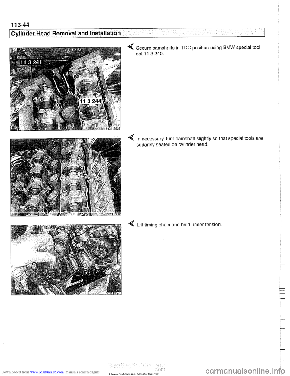
4 Secure camshafts in TDC position using BMW special tool
set
11 3 240.
4 In necessary, turn camshaft slightly so that special tools are
squarely seated on cylinder head.
4 Lift timing chain and hold under tension.