timing chain BMW 540i 2001 E39 Workshop Manual
[x] Cancel search | Manufacturer: BMW, Model Year: 2001, Model line: 540i, Model: BMW 540i 2001 E39Pages: 1002
Page 3 of 1002
Downloaded from www.Manualslib.com manuals search engine
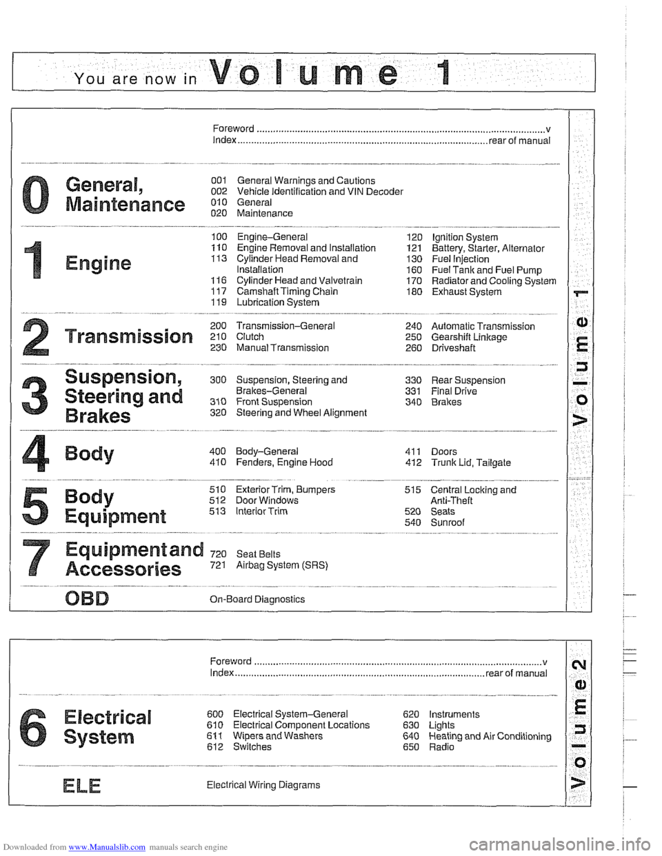
YOU are now in Volume I
I
Foreword ................... .. ........................................................................\
.......... v
Index
........................ .. ................................................................ rear of manual
General, 001 General Warnings and Cautions 002 Vehicle Identification and VIN Decoder
Maintenance OiO 020 Maintenance
Engine
100 Engine-General 110 Engine Removal and Installation
113 Cylinder Head Removal and
Installation
116 Cyiinder Head and Valvetrain 117 Camshaft Timing Chain
119 Lubrication System
200 Transmission-General
2 Transmission 210 clutch 230 ManualTransmission
I20 Ignition System
121 Battery, Starter, Alternator
130 Fuel Injection
160 Fuel Tank and Fuel Pump 170 Radiator and Cooling System
180 Exhaust System
240 Automatic Transmission
250 Gearshift Linkage 260 Driveshaft
Suspension, 300 Suspension, Steering and 330 Rear Suspension
Brakes-General 331 Final Drive
Steering and No Front Suspension 340 Brakes
320 Steering and Wheel Alignment
400 Body-General
410 Fenders, Engine Hood 411 Doors
412 Trunk Lid, Tailgate
510 Exterior Trim, Bumpers 512 Door Windows
Equipment 513 Interior Trim
7
Equipment and 720 seat Belts
Accessories 721 Airbag System (SRS)
OBD On-Board Diagnostics
. ............ ..
515 Central Lociting and
Anti-Theft
520 Seats 540 Sunroof
.................................................................... Foreword .............................. .. v
Index ................... .. ................................................................ rear of manual
Electrical
6 system
600 Electrical System-General 620 Instruments
610 Electrical Comoonent Locations 630 Liohts
611 wipers and washers 612 Switches eati in^ and Air Conditioning
Radio
. ........... ........ .........................
Electrical Wiring Diagrams
Page 68 of 1002
Downloaded from www.Manualslib.com manuals search engine
Engine-General
This section covers system descriptions and general informa-
tion on engines and engine management systems. Also cov-
ered is basic engine troubleshooting.
For specific repair procedures, refer to the appropriate repair
group:
110 Engine Removal and Installation
0 113 Cylinder Head Removal and Installation
116 Cylinder Head and Valvetrain
0 117 Camshaft Timing Chain
119 Lubrication System
120 Ignition System
130 Fuel Injection
0 170 Radiator and Cooling System
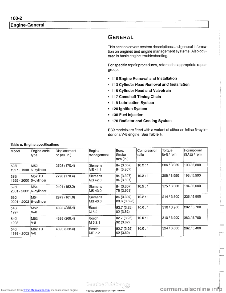
E39 models are fitted with a variant of either an inline 6-cylin-
der or a
V-8 engine. See Table a.
Table a. Engine specifications
Page 95 of 1002
Downloaded from www.Manualslib.com manuals search engine
113-1
11 3 Cylinder Head
Removal and Installation
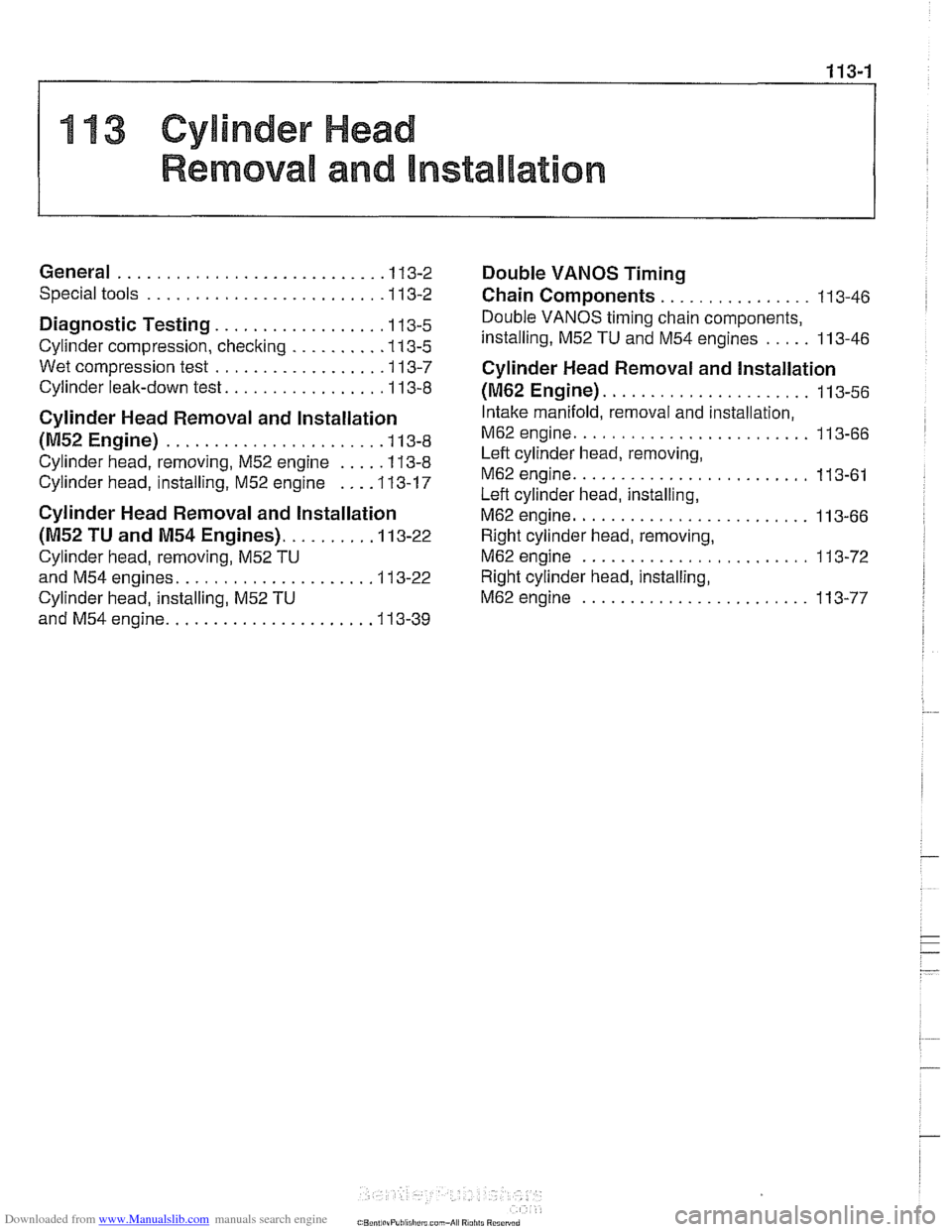
General ........................... .I 13-2
Special tools ........................ .I 13-2
Diagnostic Testing. ................ .I1 3-5
Cylinder compression, checking ......... ,113-5
Wet compression test ................. .I1 3-7
Cylinder leak-down test. ................ 11 3-8
Cylinder Head Removal and Installation
(M52 Engine) ...................... .I1 3-8
Cylinder head, removing, M52 engine .... ,113-8
Cylinder head, installing, M52 engine ... ,113-17
Cylinder Head Removal and Installation
(M52 TU and M54 Engines). ........ ,113-22
Cylinder head, removing, M52 TU
and
M54 engines. ................... .I1 3-22
Cylinder head, installing, M52 TU
and
M54 engine. .................... .I1 3-39
Double VANOS Timing
Chain Components
................ 11 3-46
Double VANOS timing chain components,
installing,
M52 TU and M54 engines ..... 113-46
Cylinder Head Removal and Installation
(M62 Engine). ..................... 11 3-56
Intake manifold, removal and installation,
M62 engine. ........................ 11 3-66
Left cylinder head, removing,
M62 engine. ........................ 11 3-61
Left cylinder head, installing,
M62 engine. ........................ 11 3-66
Right cylinder head, removing,
M62 engine ........................ 11 3-72
Right cylinder head, installing,
M62 engine ........................ 11 3-77
Page 96 of 1002
Downloaded from www.Manualslib.com manuals search engine
11 3-2
Cylinder Head Removal and Installation
This group covers cylinder head removal and installation as
well as cylinder
headlvalve diagnostic procedures.
In the procedures in this repair group, engines are referred to
by engine code. If necessary, see
100 Engine-General for
engine code and application information.
The information given in this repair group assumes that the
engine is installed in the engine bay. On the
6-cylinder en-
gines, the VANOS control unit must be removed in orderto re-
move the cylinder head from the engine block. On
M52TU
and M54 engines, camshafts must be removed from the cylin-
der head before the head is removed.
The cylinder head removal and installation procedures for the
M62 V-8 are also included, butthe proceduresforthe M62TU
V-8 with VANOS are not provided.
For cylinder head and valvetrain reconditioning information,
see
116 Cylinder Head and Valvetrain.
For specific repair procedures, refer to the appropriate repair
group:
020 Maintenance
116 Cylinder Head and Valvetrain
117 Camshaft Timing Chain
170 Radiator and Cooling System
610 Component locations
NOTE-
If a head gasket problem is suspected, a compression test or
leak-down test will usually detect the fault See Diagnostic
Testing later
in this group.
Special tools
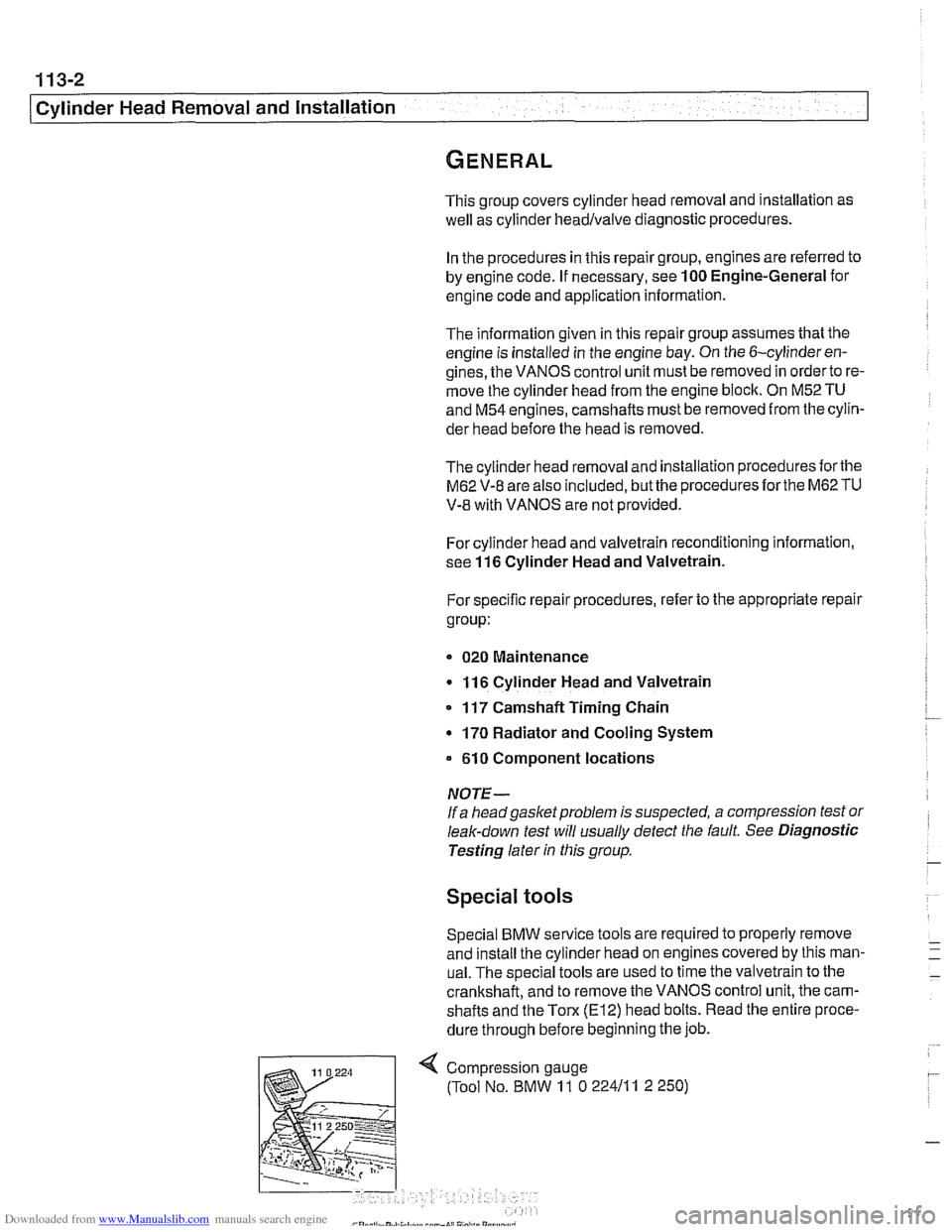
Special BMW service tools are required to properly remove
and install the cylinder head on engines covered by this man-
ual. The special tools are used to time the valvetrain to the
crankshaft, and to remove the VANOS control unit, the cam-
shafts and the
Tom (El2) head bolts. Read the entire proce-
dure through before beginning the job.
Page 97 of 1002
Downloaded from www.Manualslib.com manuals search engine
11 3-3
Cylinder Head Removal and Installation
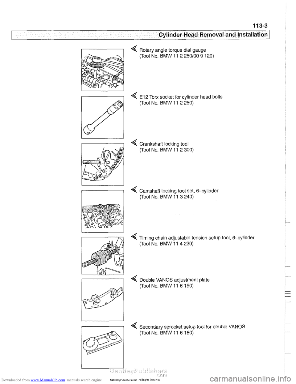
4 Rotary angle torque dial gauge
(Tool No. BMW
11 2 250100 9 120)
4 El2 Torx socket for cylinder head bolts
(Tool No.
BMW 11 2 250)
4 Crankshaft loclting tool
(Tool No.
BMW 11 2 300)
4 Camshaft locking tool set, 6-cylinder
/I (Tool No, BMW 11 3 240)
< Timing chain adjustable tension setup tool, 6-cylinder
(Tool No.
BMW 11 4 220)
>
Double VANOS adiustment date
4 Secondary sprocket setup tool for double VANOS
(Tool No. BMW
11 6 180)
Page 98 of 1002
Downloaded from www.Manualslib.com manuals search engine
11 3-4
Cylinder Head Removal and Installation
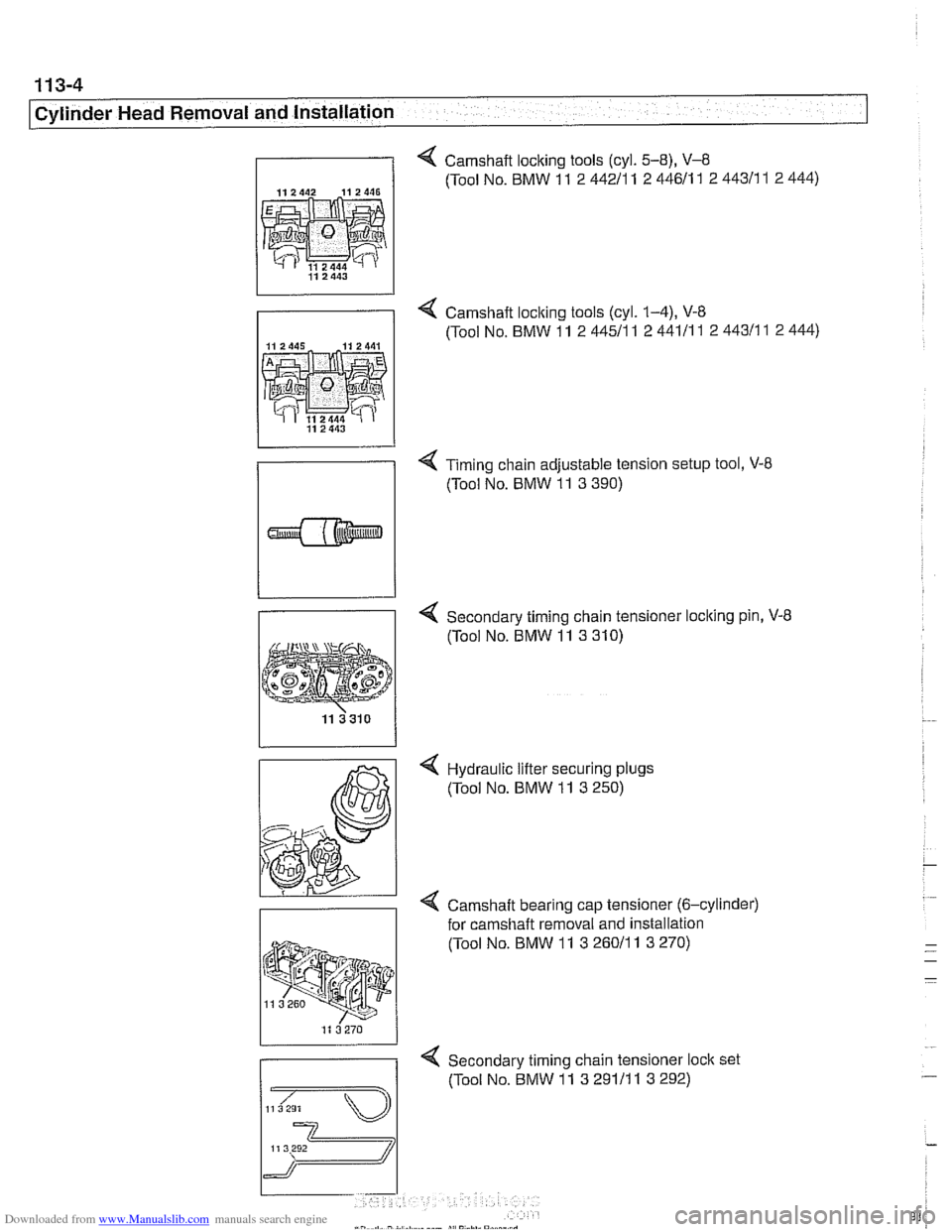
4 Camshaft locking tools (cyl. 5-8), V-8
112442 112446 (Tool No. BMW 11 2 44211 1 2 44611 1 2 44311 1 2 444)
4 Camshaft loclting tools (cyl. 1-4), V-8
(Tool No. BMW 11 2 44511
1 2 44111 1 2 44311 1 2 444)
4 Timing chain adjustable tension setup tool, V-8
(Tool No. BMW 11 3 390)
Secondary timing chain tensioner loclting pin, V-8
(Tool No. BMW 11 3 310)
4 Hydraulic lifter securing plugs
(Tool No. BMW 11 3 250)
< Camshaft bearing cap tensioner (6-cylinder)
for
camshaft removal and installation
(Tool No. BMW 11
3 26011 1 3 270)
4 Secondary timing chain tensioner loclt set
(Tool No. BMW 11 3 29111 1 3 292)
Page 107 of 1002
Downloaded from www.Manualslib.com manuals search engine
- - , -. I Cylinder Head Removal and lnstallatio~
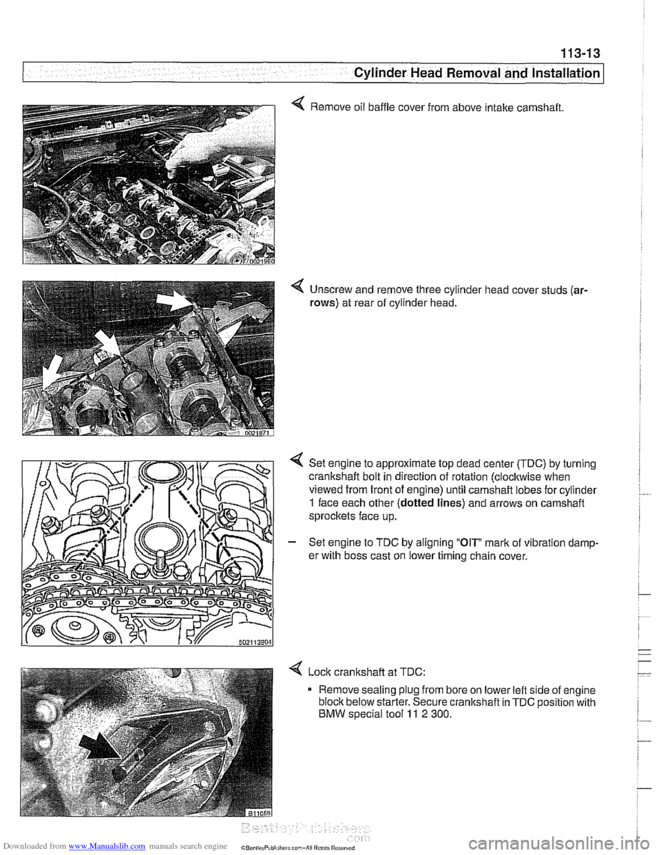
4 Remove oil baffle cover from above intake camshaft.
4 Unscrew and remove three cylinder head cover studs (ar-
rows)
at rear of cylinder head.
Set engine to approximate top dead center
(TDC) by turning
crankshaft bolt in direction of rotation (clocltwise when
viewed from front of engine) until camshaft lobes for cylinder
1 face each other (dotted lines) and arrows on camshaft
sprocltets face up.
- Set engine to TDC by aligning "OIP mark of vibration damp-
er with boss cast on lower timing chain cover.
< Lock cranltshaft at TDC:
Remove sealing plug from bore on lower left side of engine
block below starter. Secure crankshaft in
TDC position with
BMW special tool 11 2 300.
Page 110 of 1002
Downloaded from www.Manualslib.com manuals search engine
113-16
Cylinder Head Removal and Installation
- Remove secondary timing chain and sprockets:
Remove mounting nuts from front of intake camshaft
sprocket. Remove and label shim.
CAUTION-
Hold the camshaft stationary (at hex on camshaft) when loos-
ening or tightening sprocket mounting fasteners.
Remove mounting nuts from front of exhaust camshaft
sprocket and remove and label thrust washer.
NOTE-
Where applicable, make note of thrust washerpositions. The
thicker
(0.4 mm) washer is mounted outermost.
- Remove secondary sprockets together with camshaft tim-
ing chain from front of camshafts.
CAUTION-
The camshafts must be locledin the TDCposition using the
special service tool as described earlier: The arrows on the
sprockets should not be used to accurately set the engine to
TDC. The tool holds the camshafts parallel to each other and
NOTE-
Do not remove the sprocl
to
Iceep the sproclefs timed to each other:
CAUTIOI\C
The crankshaft must not be allowed to rotate once the cam-
shaft timing chain is removed. The pistons can
contact the
valves.
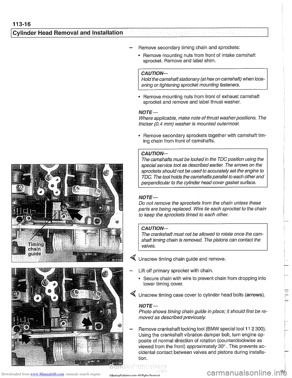
Unscrew timing chain guide and remove.
Lift off primary sprocket with chain.
Secure chain with wire to prevent chain from dropping into
lower timing cover.
Unscrew timing case cover to cylinder head bolts (arrows).
NOTE-
Photo shows timing chain guide in place; it should first be re-
moved as described previously.
Remove crankshaft locking tool
(BMW special tool 11 2 300).
Using the crankshaft vibration damper bolt, turn engine op-
posite of normal direction of rotation (counterclocltwise as
viewed from the front) approximately 30". This prevents ac-
cidental contact between valves and pistons during installa-
tion.
Page 111 of 1002
Downloaded from www.Manualslib.com manuals search engine
Cylinder Head Removal -- and lnstallati~i
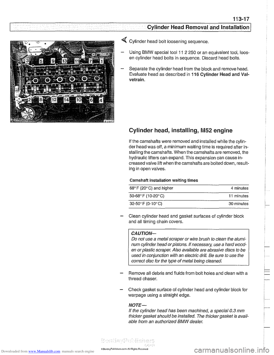
4 Cylinder head bolt loosening sequence.
- Using BMW special tool 11 2 250 or an equivalent tool, loos-
en cylinder head bolts in sequence. Discard head bolts.
- Separate the cylinder head from the block and remove head.
Evaluate head as described in
116 Cylinder Head and Val-
vetrain.
Cylinder head, installing, M52 engine
If the camshafts were removed and installed while the cylin-
der head was off, a minimum waiting time is required after in-
stalling the camshafts. When the camshafts are removed, the
hydraulic lifters can expand. This expansion can cause in-
creased valve lift when the camshafts are bolted down, result-
ing in open valves.
Camshaft installation waiting times
68" F (20" C) and higher 4 minutes
50.68' F (1 0-20" C) 11 minutes
32-50' F (0-1 0" C) 30 minutes
- Clean cylinder head and gasket surfaces of cylinder block
and all timing chain covers.
CAUTION-
Do not use a metal scraper or wire brush to clean the alumi-
num cylinder head orpistons. If necessary, use a hard wood-
en orplastic scraper. Also available are abrasive discs to be
used in conjunction with an electric drill. Be sure to use the
correct disc for the type of metal being cleaned.
- Remove all debris and fluids from bolt holes and clean with a
thread chaser.
- Check gasket surface of cylinder head and cylinder block for
warpage using a straight edge.
NOTE-
If the cylinder head has been machined, a special 0.3 mm
thicker gasket should be installed. The thicker
gasket is avail-
able from an authorized
BMW dealer.
Page 112 of 1002
Downloaded from www.Manualslib.com manuals search engine
I Cylinder Head Removal and Installation
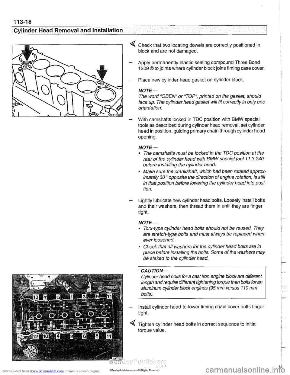
4 Check that two locating dowels are correctly positioned in
block and are not damaged.
- Apply permanently elastic sealing compound Three Bond
1209 8 to joints where cylinder block joins timing case cover.
- Place new cylinder head gasket on cylinder block.
NOTE-
The word "OBEN" or 'TOP': printed on the gasket, should
face up. The cylinder head
gasket will fit correctly in only one
orientation.
- With camshafts locked in TDC oosition with BMW soecial
tools as described during cylinder head removal,
seicylinder
head in position, guiding primary chain through cylinder head
opening.
NOTE-
* The camshafts must be locl(ed in the TDC position at the
rear of the cylinder head with
BMW special tool I1 3 240
before installing the cylinder head.
Make sure the
cranksha% which had been rotated approx-
imately
30" opposite the direction of engine rotation, is still
in that position before lowering the cylinder head into posi-
tion.
- Lightly lubricate new cylinder head bolts. Loosely install bolts
and their washers, then thread them in until they are finger
tight.
NOTE-
. Torx-type cylinder head bolts should not be reused. They
are stretch-type bolts and must always be replaced when-
ever loosened.
Check that all washers for the cylinder head bolts are in
place before installing the bolts. Some of the washers may
be
stalced to the cylinder head.
CAUTIOI\C
Cylinder head bolts for a cast iron engine block are different
length and require different tightening torque than bolts for an
aluminum cylinder bloclc engines
(95 rnm versus 110 rnm
bolts).
- Install cylinder head-to-lower timing chain cover bolts finger
tight.
< Tighten cylinder head bolts in correct sequence to initial
torque value.