Engine removal BMW 540i 2001 E39 Workshop Manual
[x] Cancel search | Manufacturer: BMW, Model Year: 2001, Model line: 540i, Model: BMW 540i 2001 E39Pages: 1002
Page 894 of 1002
Downloaded from www.Manualslib.com manuals search engine
51 3-1 6
Interior Trim
Glove compartment, removing and
installing
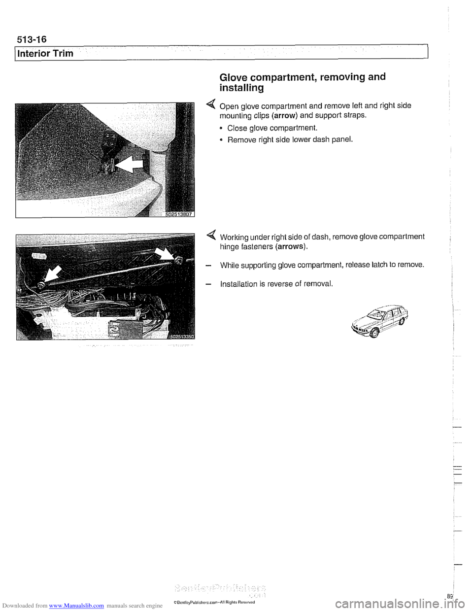
4 Open glove compartment and remove lefl and right side
mounting clips
(arrow) and support straps.
Close glove compartment.
Remove right side lower dash panel.
4 Working under right side of dash, remove glove compartment
hinge fasteners
(arrows).
- While supporting glove compartment, release latch to remove.
- Installation is reverse of removal.
, &j?i 8 .: ,,,, < I;; ,..9;:*?:4 *-,;: ,,
Page 904 of 1002
Downloaded from www.Manualslib.com manuals search engine
1 Central Locking and Anti-Theft
NOJE-
A single unlock request from the driver's door with the FZV
key unlocks the driver's door only.
A second unlock request
unlocls the remaining doors and trunk. This feature can be
modified for individual users with the Key Memory capabil-
ities to activate all lock actuators simultaneously See Car
Memory
/ Key Memory later in this section.
Starting with 2000 models, the battery in the FZV ignition
Icey is recharged by the ignition switch ring antenna while
the ley is in the ignition switch.
Transmitter self-test (models to
1999)
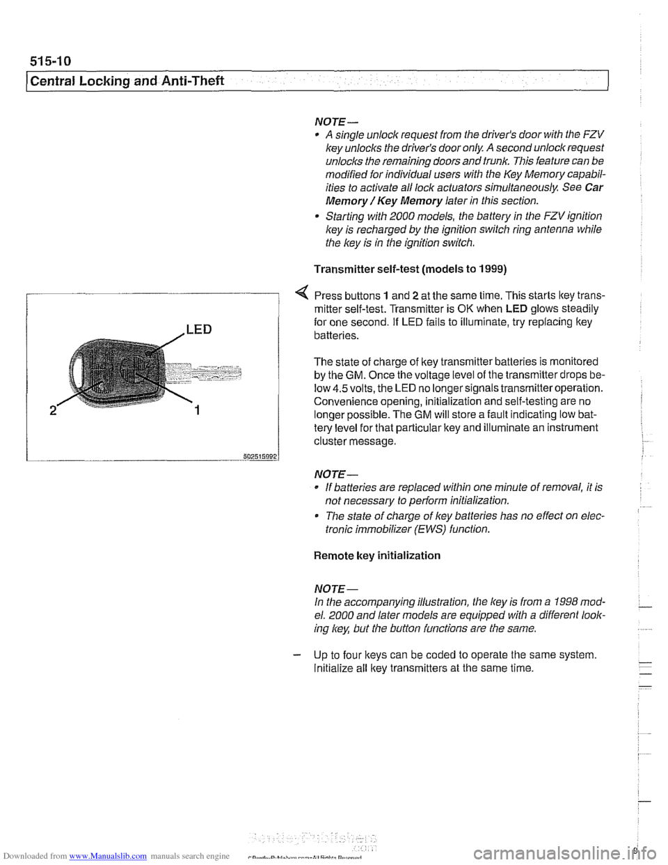
Press buttons 1 and 2 at the same time. This starts ltey trans-
/ mitter self-test. Transmitter is OK when LED glows steadily
te{le"el for that particular key and illuminate an instrument
cluster message.
-- 502515092 J
NO JE-
If batteries are replaced within one minute of removal, it is
not necessary to
periorm initialization.
Tlie state of charge of key batteries has no effect on elec-
tronic immobilizer (EWS) function.
2
Remote key initialization
for one second. If LED fails to illuminate, try replacing ltey~
batteries.
The state of charge of key transmitter batteries is monitored
by the
GM. Once the voltage level of the transmitter drops be-
low
4.5volts, the LED no longersignals transmitteroperation.
Convenience opening, initialization and self-testing are no
lonaer ~ossible. The GM will store a fault indicatina low bat-
NOJE-
In the accompanying illustration, the key is from a 1998 mod-
el. 2000 and later models are equipped with a different look-
ing
/
Initialize all key transmitters at the same time.
Page 910 of 1002
Downloaded from www.Manualslib.com manuals search engine
51 5-1 6
Central Locking and Anti-Theft
DOOR HANDLES AND LOCKS
In the procedures that follow, door handle removal, door lock
cylinder removal and door latch removal are covered for the
left front door. Other doors are similar although simpler, due
to the
lack of lock cylinder.
Inside door release removal is covered in the procedure for
inner door
ane el removal. See 411 Doors.
Door handle (outer), removing and
installing
NOTE-
IfBMWspecial tools 51 3201 and51 3 203 are available, the
door handle can be removed without removing the door trim
panel or door
airbag. Use the access hole behind the rubber
sealing plug on the door edge.
- Close window on front door.
- Disconnect battery negative (-) cable.
CAUTlOG
Prior to disconnecting the batter)! read the battery discon-
nection cautions given
in 001 General Warnings and Cau-
tions.
Remove front door trim panel. See 411 Doors.
Remove door-mounted air bag. See 721
Airbag System
(SRS).
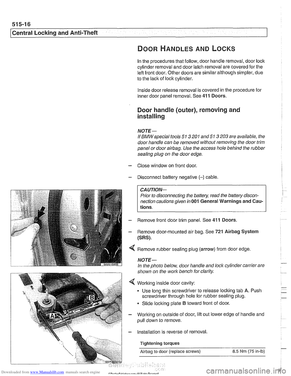
Remove rubber sealing plug (arrow) from door edge
NOTE-
In the photo below, door handle and lock cylinder carrier are
shown on the work bench for clarity.
Working inside door cavity:
- Use long thin screwdriver to release locking tab A. Push
screwdriver through hole for rubber sealing plug.
Slide locking plate
B toward front of door.
Working on outside of door, lift out lower edge of handle and
pull down to remove.
Installation is reverse of removal,
Tightening torques
Airbag to door (replace screws) 8.5 Nrn (75 in-lb)
Page 912 of 1002
Downloaded from www.Manualslib.com manuals search engine
51 5-1 8
I Central Locking and Anti-Theft
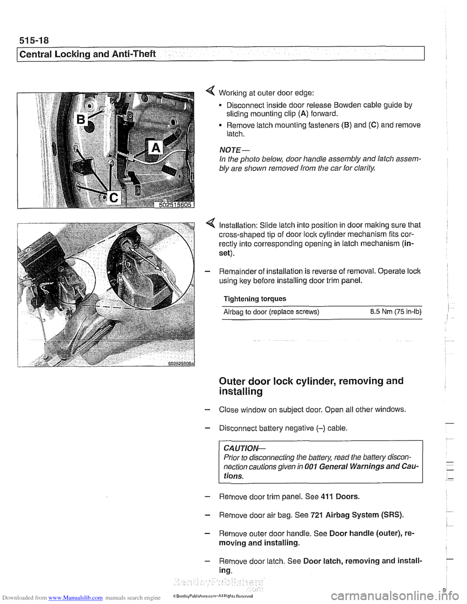
< Working at outer door edge:
Disconnect inside door release
Bowden cable guide by
sliding mounting clip (A) forward.
Remove latch mounting fasteners
(B) and (C) and remove
latch.
NOTE-
In the photo below, door handle assembly and latch assem-
bly are shown removed from the car
for clarity.
Installation: Slide latch into position in door making sure that
cross-shaped tip of door
loclc cylinder mechanism fits cor-
rectly into corresponding opening in latch mechanism (in-
set).
Remainder of installation is reverse of removal. Operate
loclc
using key before installing door trim panel.
Tightening torques
Airbag to door (replace screws) 8.5 Nm (75 in-lb)
Outer door lock cylinder, removing and
installing
- Close window on subject door. Open all other windows
- Disconnect battery negative (-) cable.
CA UTIOIG
Prior to disconnecting the baffeg read the battery discon-
nection cautions given in
001 General Warnings and Cau-
tions.
- Remove door trim panel. See 411 Doors.
- Remove door air bag. See 721 Airbag System (SRS).
- Remove outer door handle. See Door handle (outer), re-
moving and installing.
- Remove door latch. See Door latch, removing and install-
ing.
Page 913 of 1002
Downloaded from www.Manualslib.com manuals search engine
Central Locking and Anti-Theft
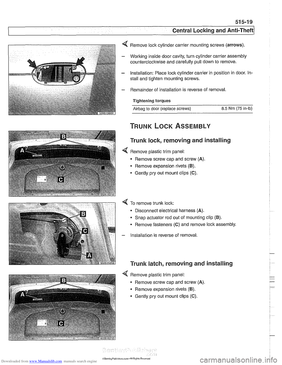
4 Remove lock cylinder carrier mounting screws (arrows).
- Working inside door cavity, turn cylinder carrier assembly
counterclockwise and carefully pull down to remove.
- Installation: Place lock cylinder carrier in position in door. In-
stall and tighten mounting screws.
- Remainder of installation is reverse of removal.
Tightening torques
Airbag to door (replace screws) 8.5 Nm (75 in-lb)
Trunk lock, removing and installing
< Remove plastic trim panel:
- Remove screw cap and screw (A).
Remove expansion rivets (B).
* Gently pry out mount clips (C).
4 To remove trunk lock:
Disconnect electrical harness
(A).
* Snap actuator rod out of mounting clip (B).
Remove fasteners (C) and remove lock assembly.
- Installation is reverse of removal
Trunk latch, removing and installing
4 Remove plastic trim panel:
Remove screw cap and screw
(A).
Remove expansion rivets (B).
Gently pry out mount clips (C).
Page 914 of 1002
Downloaded from www.Manualslib.com manuals search engine
515-20
Central Locking and Anti-Theft
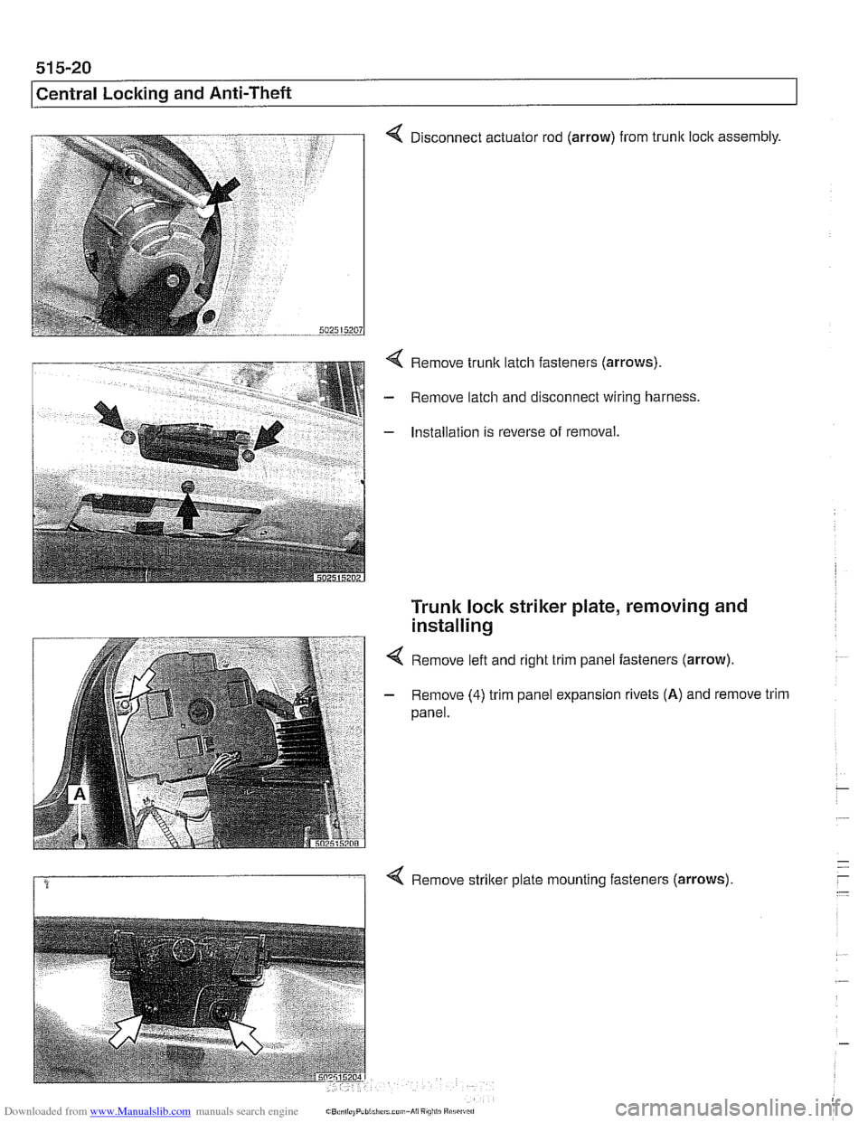
4 Disconnect actuator rod (arrow) from trunk loclc assembly.
4 Remove trunk latch fasteners (arrows).
- Remove latch and disconnect wiring harness.
- Installation is reverse of removal.
Trunk lock striker plate, removing and
installing
4 Remove left and right trim panel fasteners (arrow).
- Remove (4) trim panel expansion rivets (A) and remove trim
panel.
1 4 Remove striker plate mounting fasteners (arrows).
Page 917 of 1002
Downloaded from www.Manualslib.com manuals search engine
Central Lockina and ~nti- heft
EWS control module, replacing
NOTE-
EWS control module location varies depending on version of
EWS installed.
Checlc the table €39 EWS applications.
- Disconnect battery negative (-) cable.
CA UTIOI\C
Prior to disconnecting the battery, read the battery discon-
nection cautions given in
001 General Warnings and Cau-
tions.
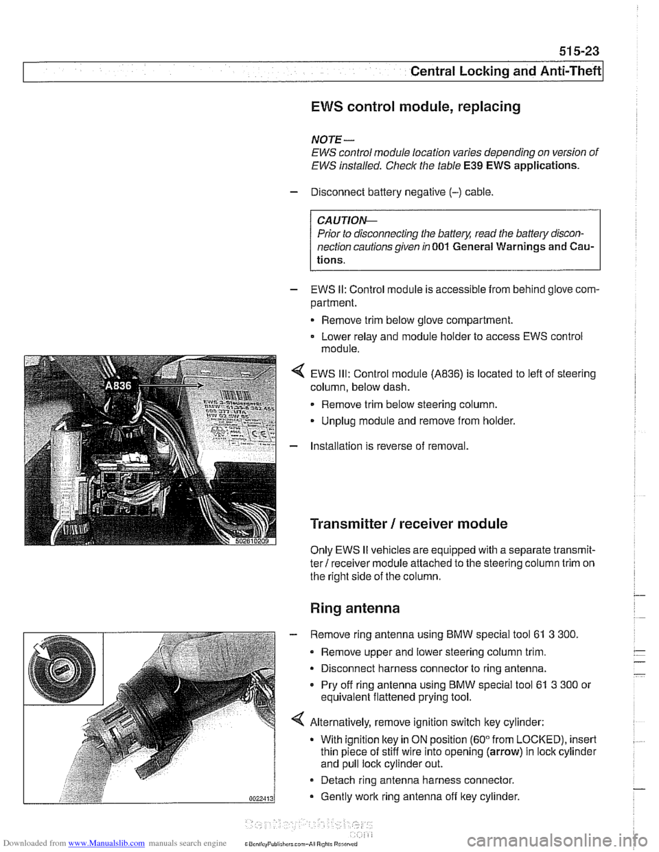
- EWS II: Control module is accessible from behind glove com-
partment.
Remove trim below glove compartment.
Lower relay and module holder to access EWS control
module
EWS
Ill: Control module (A836) is located to left of steering
column, below dash.
Remove trim below steering column.
Unplug module and remove from holder.
Installation is reverse of removal.
Transmitter / receiver module
Only EWS II vehicles are equipped with a separate transmit-
ter! receiver module attached to the steering column trim on
the right side of the column.
Ring antenna
- Remove ring antenna using BMW special tool 61 3 300.
Remove upper and lower steering column trim.
Disconnect harness connector to ring antenna.
Pry off ring antenna using
BMW special tool 61 3 300 or
equivalent flattened prying tool.
Alternatively, remove ignition switch key cylinder: With ignition
ltey in ON position (60" from LOCKED), insert
thin piece of stiff wire into opening (arrow) in lock cylinder
and pull lock cylinder out.
- Detach ring antenna harness connector.
Gently
work ring antenna off ltey cylinder.
CaonliayPuliiliirrl can,-A, R0,il. Rurilrrrri
Page 922 of 1002
Downloaded from www.Manualslib.com manuals search engine
l Seats
This repair group covers removal and installation of the front
and rear seat.
SeatIMirrorlSteering Column Memory
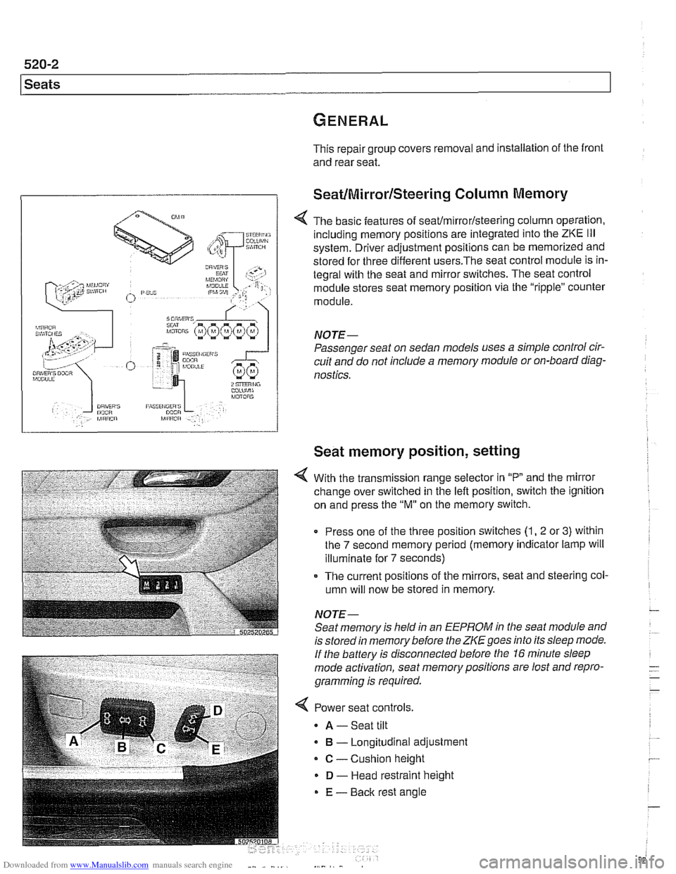
< The basic features of seaffmirrorlsteering column operation,
including memory positions are integrated into the
ZKE Ill
system. Driver adjustment positions can be memorized and
stored for three different
users.The seat control module is in-
tegral with the seat and mirror switches. The seat control
module stores seat memory position via the "ripple" counter
module.
NOTE-
Passenger seat on sedan models uses a simple control cir-
cuit and do not include a memory module or on-board diag-
nostics.
Seat memory position, setting
With the transmission range selector in "P and the mirror
change over switched in the left position, switch the ignition
on and press the
"M" on the memory switch.
Press one of the three position switches
(1, 2 or 3) within
the
7 second memory period (memory indicator lamp will
illuminate for
7 seconds)
- The current positions of the mirrors, seat and steering col-
umn will now be stored in memory.
NOTE- Seat memory is held in an
EEPROM in the seat module and
is stored in memory before the
ZKE goes into its sleep mode.
If the battery is disconnected before the 16 minute sleep
mode activation, seat memorypositions are lost and repro-
gramming is required.
< Power seat controls.
A -Seat tilt
B - Longitudinal adjustment
C - Cushion height
D - Head restraint height
E - Back rest angle
Page 927 of 1002
Downloaded from www.Manualslib.com manuals search engine
Seats
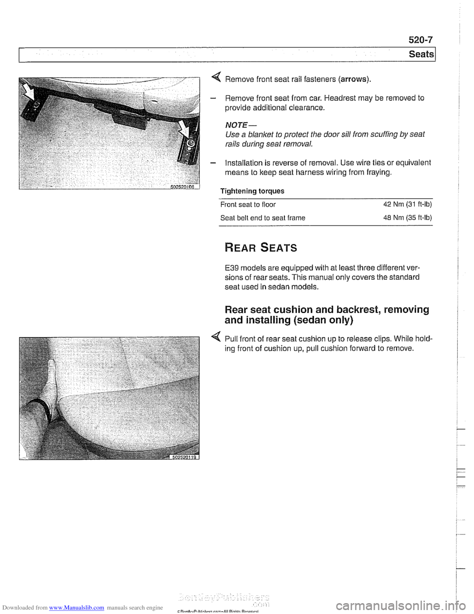
< Remove front seat rail fasteners (arrows)
- Remove front seat from car. Headrest may be removed to
provide additional clearance.
NOTE-
Use a blanket to protect the door sill from scuffing by seat
rails
during seat removal.
- Installation is reverse of removal. Use wire ties or equivalent
means to keep seat harness wiring from fraying.
Tightening torques
Front seat to floor
42 Nm (31 ft-lb)
Seat belt end to seat frame
48 Nm (35 ft-lb)
E39 models are equipped with at least three different ver-
sions of rear seats. This manual only covers the standard
seat used in sedan models.
Rear seat cushion and backrest, removing
and installing (sedan only)
4 Pull front of rear seat cushion up to release clips. While hold-
ing front of cushion up, pull cushion forward to remove.
Page 928 of 1002
Downloaded from www.Manualslib.com manuals search engine
Seats
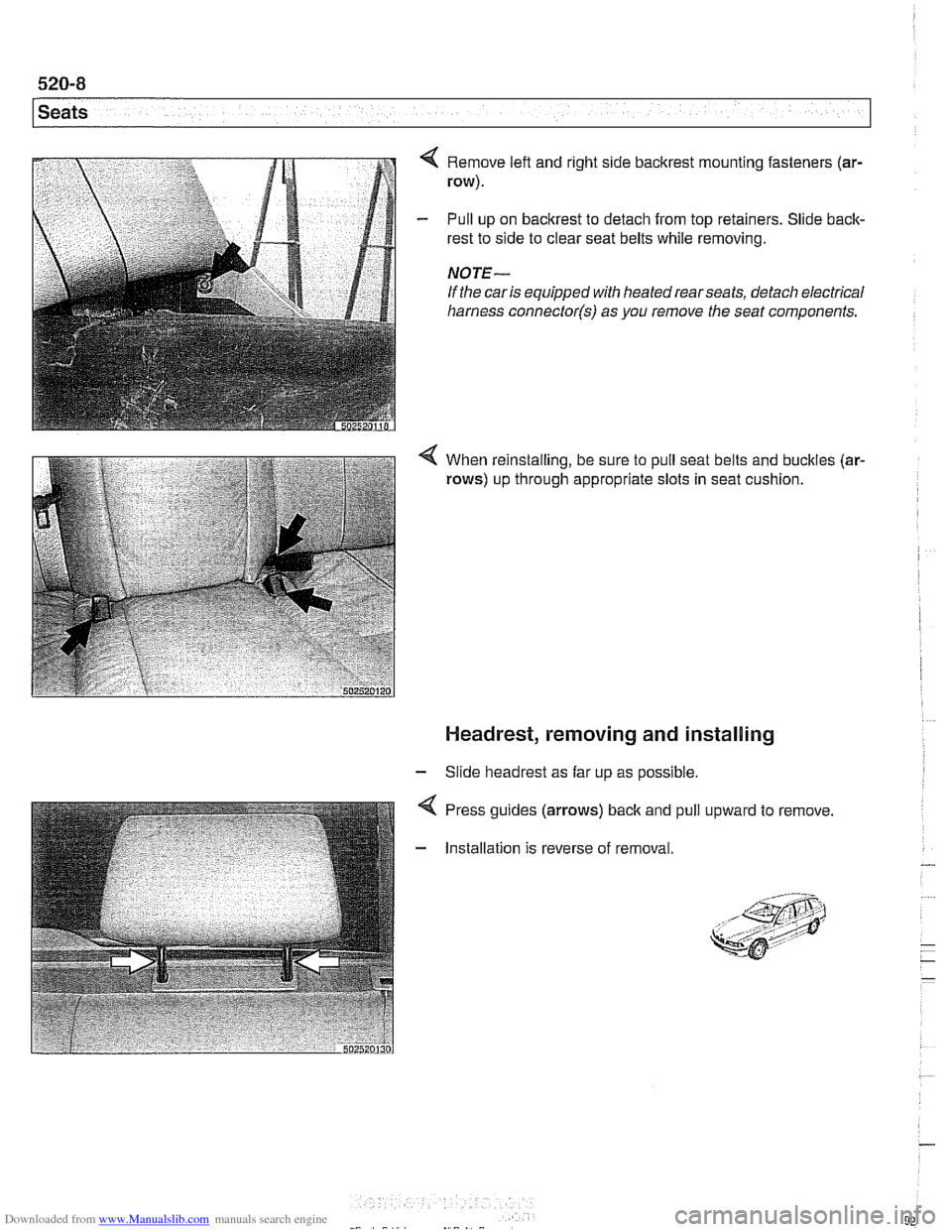
Remove left and right side bacltrest mounting fasteners (ar-
row).
Pull up on backrest to detach from top retainers. Slide back-
rest to side to clear seat belts while removing.
NOTE-
If the car is equipped with heatedrearseats, detach electrical
harness
connector(s) as you remove the seat components.
4 When reinstalling, be sure to pull seat belts and buckles (ar-
rows) up through appropriate slots in seat cushion.
Headrest, removing and installing
- Slide headrest as far up as possible.
Press guides (arrows)
back and
Installation is reverse of removal pull
upward to remove