Engine removal BMW 540i 2001 E39 Workshop Manual
[x] Cancel search | Manufacturer: BMW, Model Year: 2001, Model line: 540i, Model: BMW 540i 2001 E39Pages: 1002
Page 930 of 1002
Downloaded from www.Manualslib.com manuals search engine
540-2
Sunroof
This repair group covers the slide-tilt sunroof assembly.
There are two types of sunroof panels available: steel
01
glass. Service procedures are different for each type.
Component locations, initialization, sunroof panel replace-
ment, and sunroof height adjustment are covered. Replace-
ment of the cable assembly or frame require that the
headliner be removed. Removal and repair of the sunroof as-
sembly and othercomponents inside the roof cavity is beyond
the scope of this manual.
When the sunroof is set to the vent position (rear of panel up),
the inside headliner moves rearward approximately
120 mm
(4.7 in) This provides cabin ventilation with less wind noise. A
water channel is incorporated into the sunroof assembly. It
automatically rises when the sunroof panel is in the vent posi-
tion and prevents water from entering the interior during brak-
ing.
Sunroof electronic controls, initializing
- Initialize the sunroof in the following situations:
Malfunctions
such as lack of one-touch function, lack of
comfort openinglclosing or lack of safety (anti-trapping)
features.
If sunroof motor has been removed and reinstalled.
If power supply to the sunroof has been interrupted.
If repairs have been performed on the slideltilt mechanism.
NOTE -
The initialization sequence is dependent on the software ver-
sion of
tlie sunroof module (in the sunroof drive unit).
I WARNING -
I There is no anti-trapping protection during initialization. I
Page 936 of 1002
Downloaded from www.Manualslib.com manuals search engine
1 Sunroof
Sunroof assembly removal and installation involves headliner
removal, and is not covered in this manual. After sunroof re-
pairs, be sure to follow initialization and adjustment proce-
dures given earlier.
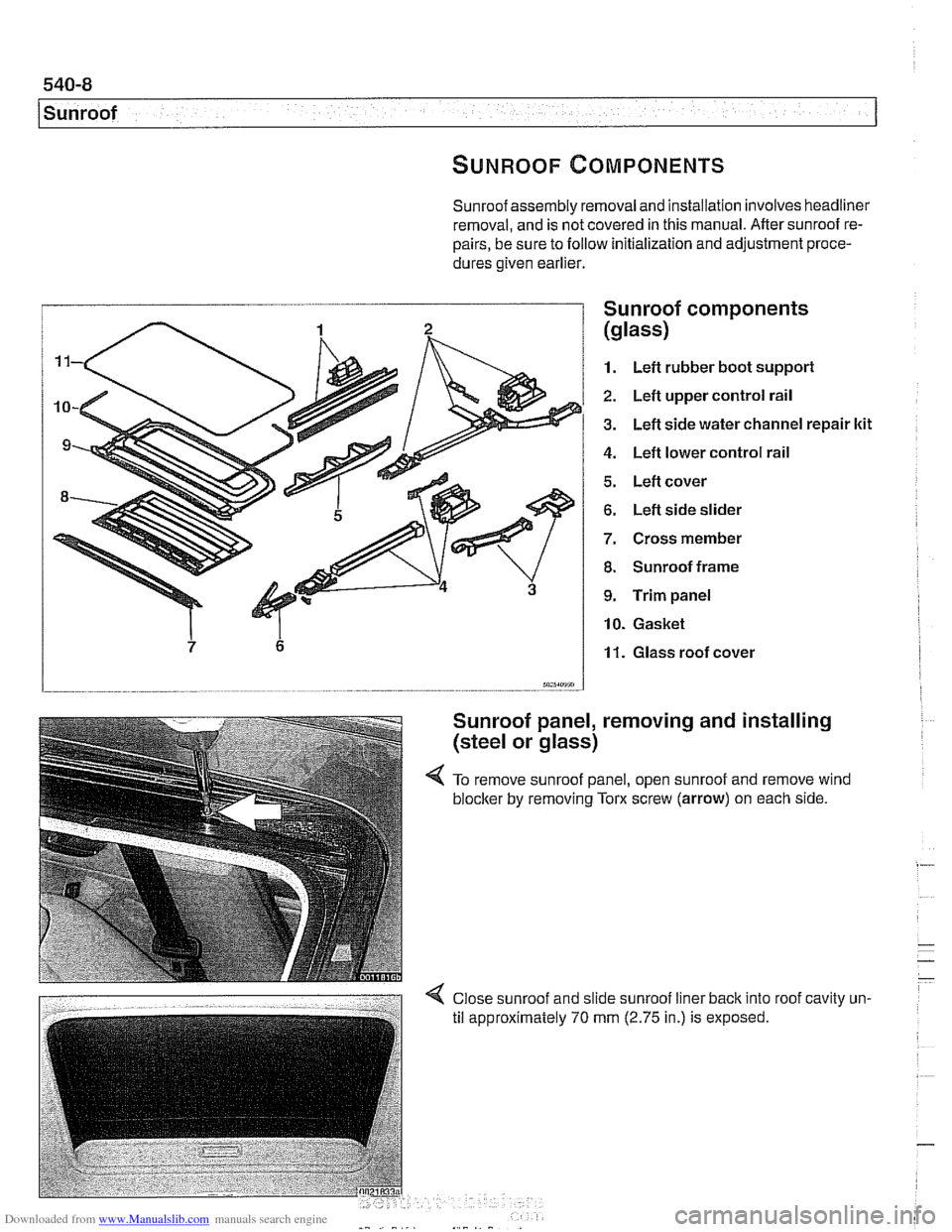
I Sunroof comDonents
1. Left rubber boot suppori
2. Left upper control rail
3. Left side water channel repair ltit
4. Left lower control rail
5. Left cover
6. Left side slider
7. Cross member
8. Sunroof frame
9. Trim panel
10. Gasket
11. Glass roof cover
m5sm.7 - -.
Sunroof panel, removing and installing
(steel or glass)
4 To remove sunroof panel, open sunroof and remove wind
blocker
by removing Tom screw (arrow) on each side.
Page 937 of 1002
Downloaded from www.Manualslib.com manuals search engine
Sunroof
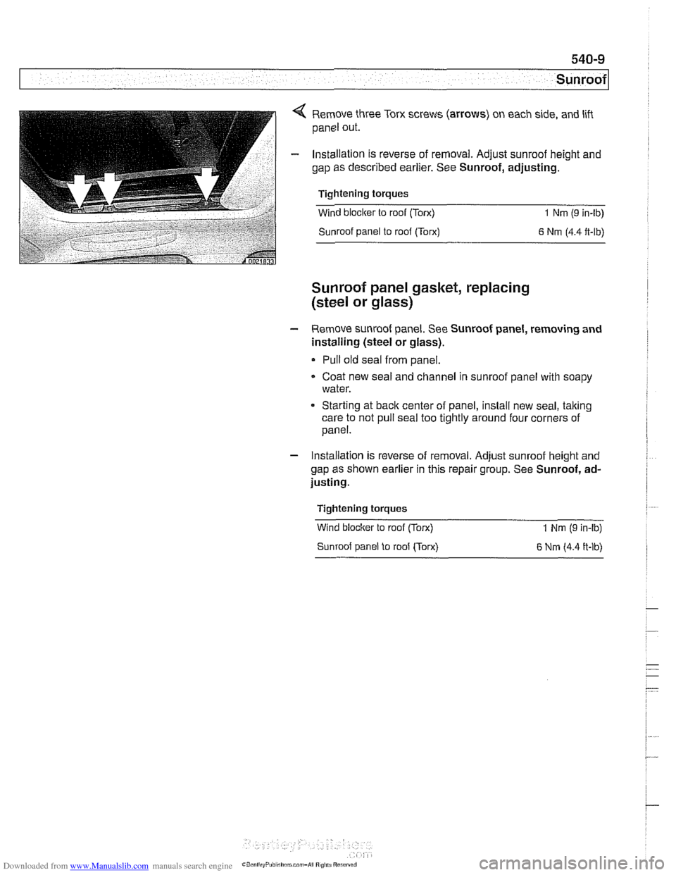
4 Remove three Torx screws (arrows) on each side, and lift
panel out.
- Installation is reverse of removal. Adjust sunroof height and
gap as described earlier. See Sunroof, adjusting.
Tightening torques
Wind blocker to roof (Torx)
1 Nm (9 in-lb)
Sunroof panel to roof (Torx)
6 Nm (4.4 ft-lb)
Sunroof panel gasket, replacing
(steel
or glass)
- Remove sunroof panei. See Sunroof panei, removing and
installing (steel or glass).
Pull old seal from panel.
Coat new seal and channel in sunroof panel with soapy
water.
* Starting at back center of panel, install new seal, taking
care to not pull seal too tightly around four corners of
panel.
- Installation is reverse of removal. Adjust sunroof height and
gap as shown earlier in this repair group. See Sunroof, ad-
justing.
Tightening torques
Wind
bloclter to roof (Torx)
Sunroof panel to roof (Torx) 1 Nm (9 in-lb)
6 Nrn (4.4 ft-lb)
Page 938 of 1002
Downloaded from www.Manualslib.com manuals search engine
.-
Sunroof
Sunroof motor, replacing
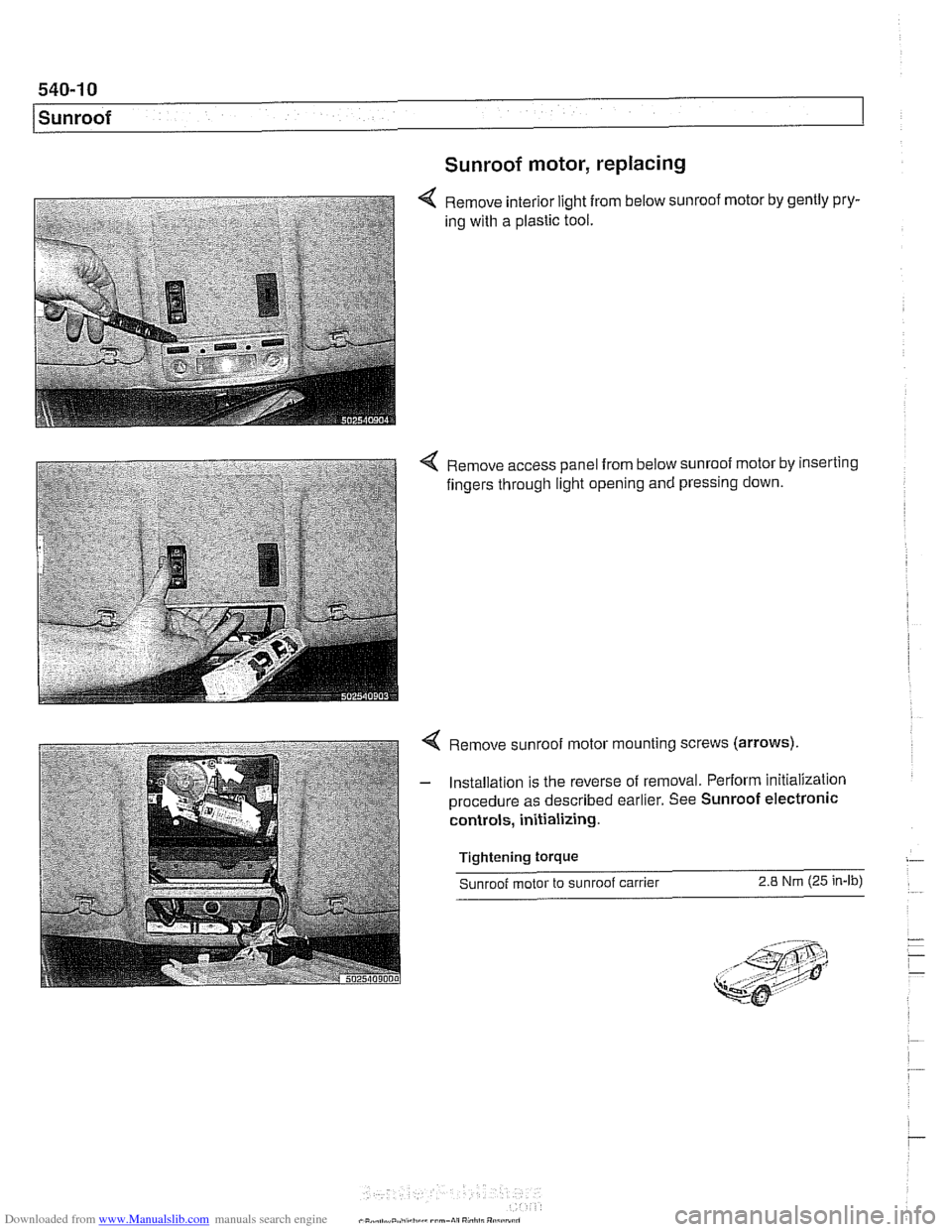
Remove interior light from below sunroof motor by gently pry-
ing with a plastic tool.
4 Remove access panel from below sunroof motor by inserting
fingers through light opening and pressing down.
4 Remove sunroof motor mounting screws (arrows).
- Installation is the reverse of removal. Perform initialization
procedure as described earlier. See Sunroof electronic
controls, initializing.
Tightening
torque
Sunroof motor to sunroof carrier 2.8 Nm (25 in-lb)
Page 946 of 1002
Downloaded from www.Manualslib.com manuals search engine
720-8
I Seat Belts
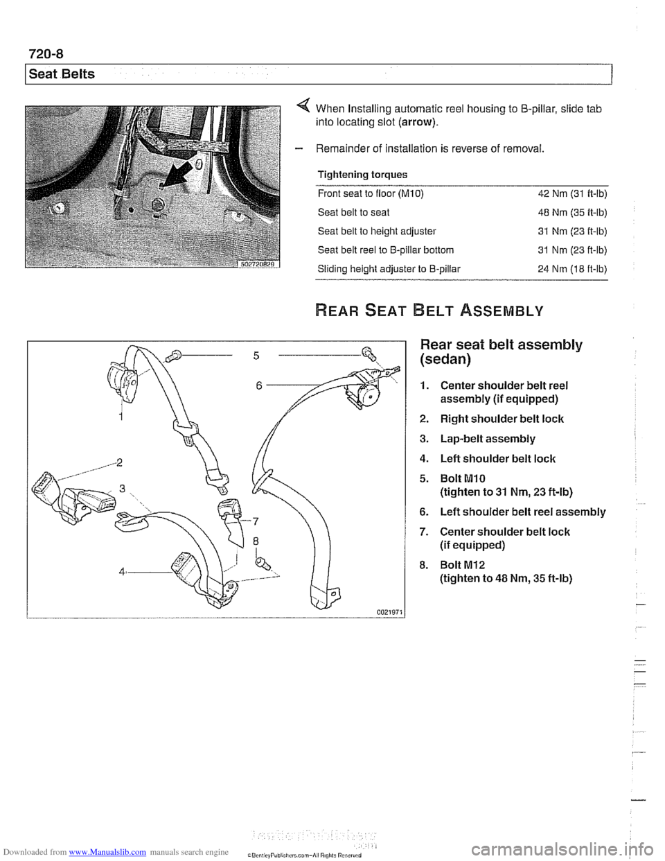
When Installing automatic reel housing to 5-pillar, slide tab
into locating slot (arrow).
Remainder of installation is reverse of removal
Tightening torques
- -.
Front seat to floor (M10) 42 Nm (31 ft-lb)
Seat belt to seat 48 Nm (35 ft-lb)
Seat belt to height adjuster 31 Nm
(23 it-lb)
Seat belt reel to €3-pillar bottom 31 Nm (23 ft-lb)
Sliding height adjuster to €3-pillar
24 Nm (18 ft-lb)
Rear seat belt assembly
(sedan)
1. Center shoulder belt reel
assembly
(if equipped)
2. Right shoulder belt lock
3. Lap-belt assembly
4. Left shoulder belt lock
5. Bolt MlO
(tighten to 31 Nm, 23 ft-lb)
6. Left shoulder belt reel assembly
7. Center shoulder belt lock
(if equipped)
8. Bolt M12
(tighten to 48 Nm, 35 ft-lb)
Page 955 of 1002
Downloaded from www.Manualslib.com manuals search engine
Airbag System (SRS)~
MRS control module, replacing
- Disconnect negative (-) cable from battery and cover nega-
tive terminal with insulating material.
CAUTIOI\C
Prior to disconnecting the battery, read the battery discon-
nection cautionsgiven in001 General Warnings and
Cau-
tions.
- Remove center console between front seats. See 513 lnteri-
or Trim.
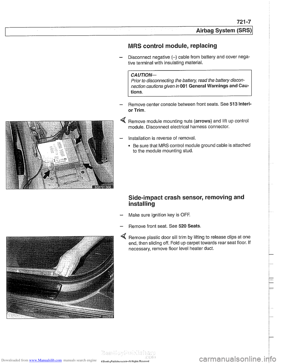
Remove module mounting nuts (arrows) and lift up control
module. Disconnect electrical harness connector.
Installation is reverse of removal.
Be sure that MRS control module ground cable is attached
to the module mounting stud.
Side-impact crash sensor, removing and
installing
- Make sure ignition key is OFF.
- Remove front seat. See 520 Seats.
Remove plastic door sill trim by lifting to release clips at one
end, then sliding off. Fold up carpet towards rear seat floor. If
necessary, remove floor level heater duct.
Page 956 of 1002
Downloaded from www.Manualslib.com manuals search engine
721 -8
(Airbag System (SRS)
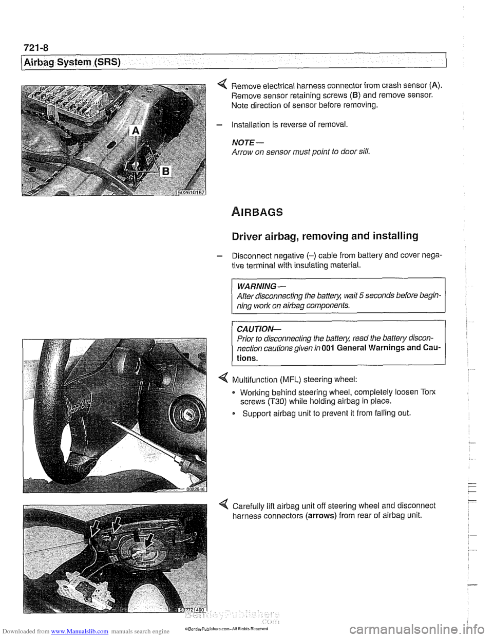
4 Remove electrical harness connector from crash sensor (A).
Remove sensor retaining screws (6) and remove sensor.
Note direction of sensor before removing.
- Installation is reverse of removal,
NOTE -
Arrow on sensor must point to door sill.
Driver airbag, removing and installing
- Disconnect negative (-) cable from battery and cover nega-
tive terminal with insulating material.
WARNING-
After disconnecting the batter)! wait 5 seconds before begin-
ning work on
airbag components.
CAUTION-
Prior to disconnecting the batter)! read the battery discon-
nection cautionsgiven
in001 General Warnings and Cau-
tions.
4 Multifunction (MFL) steering wheel:
. Working behind steering wheel, completely loosen Torx
screws
(T30) while holding airbag in place.
Support
airbag unit to prevent it from falling out.
Page 957 of 1002
Downloaded from www.Manualslib.com manuals search engine
721 -9
Airbaq System ~SRS)~
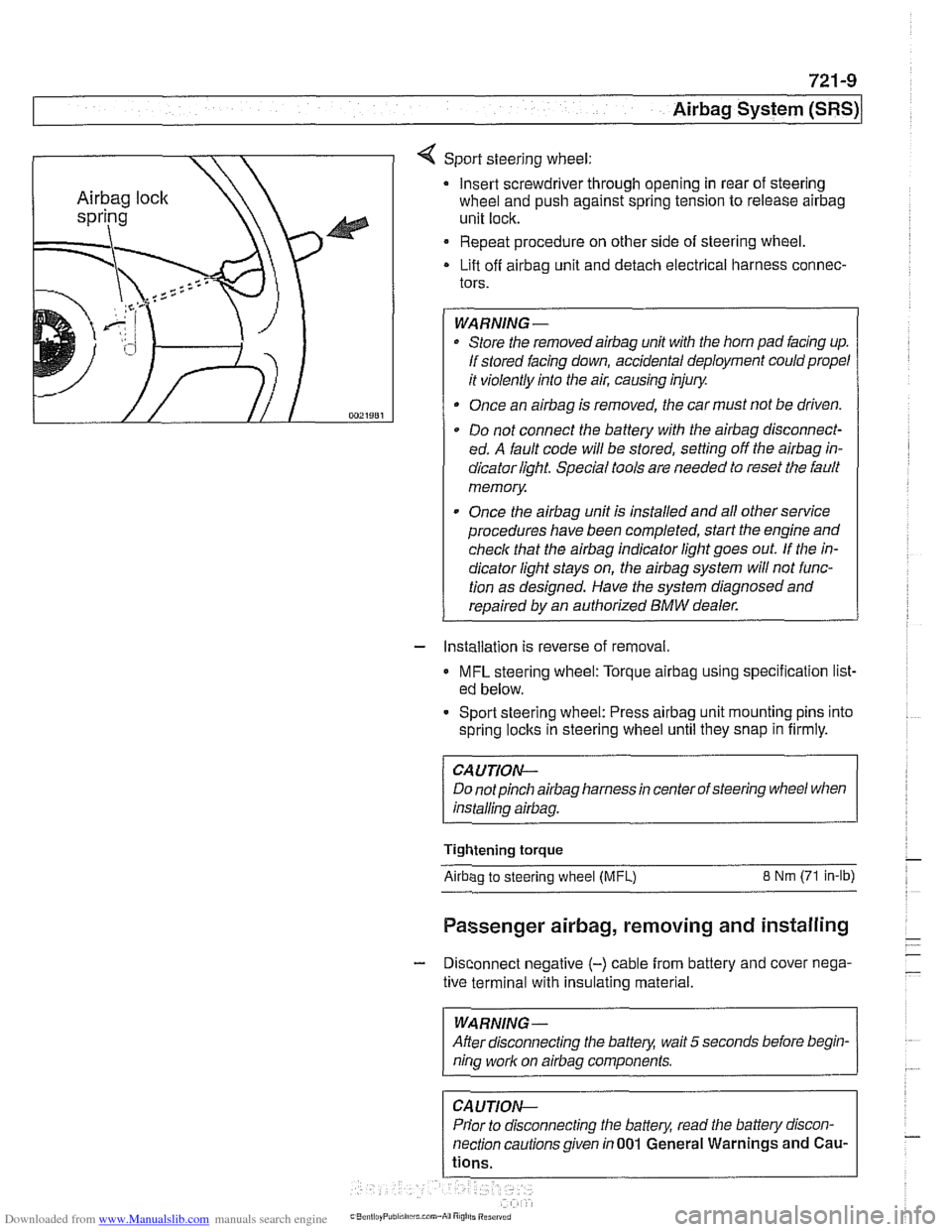
4 Sport steering wheel:
Insert screwdriver through opening in rear of steering
wheel and push against spring tension to release
airbag
unit lock.
Repeat procedure on other side of steering wheel.
Lift off
airbag unit and detach electrical harness connec-
tors.
WARNING-
Store the removedairbag unit with the horn pad facing up.
If stored facing down, accidental deployment could propel
it violently into the air, causing injury.
Once an
airbag is removed, the car must not be driven.
Do not connect the battery with the
airbag disconnect-
ed. A fault code will be stored, setting off the
airbag in-
dicator light Special tools are needed to reset the fault
memory
Once the
airbag unit is installed and all other service
procedures have been completed, start the engine and
check that the
airbag indicator light goes out. If the in-
dicator light stays on, the
airbag system will not func-
tion as designed. Have the system diagnosed and
repaired by an authorized
BMW dealer.
- Installation is reverse of removal.
MFL steering wheel: Torque airbag using specification list-
ed below.
- Sport steering wheel: Press airbag unit mounting pins into
spring
loclts in steering wheel until they snap in firmly.
CAUTION--
Do notpinch airbag harness in center of steering wheel when
installino
airbaa.
Tightening torque
Airbao to steerino wheel IMFL) 8 Nm (71 in-lb)
Passenger airbag, removing and installing
- Disconnect negative (-) cable from battery and cover nega-
tive terminal with insulating material.
--
WARNING -
After disconnecting the batteg wait 5 seconds before begin-
nina work on airbaa components.
Prior to disconnecting the battery, read the battery discon-
nection cautionsgiven in001 General Warnings and
Cau-
Page 958 of 1002
Downloaded from www.Manualslib.com manuals search engine
721 -1 0
/Airbag System (SRS)
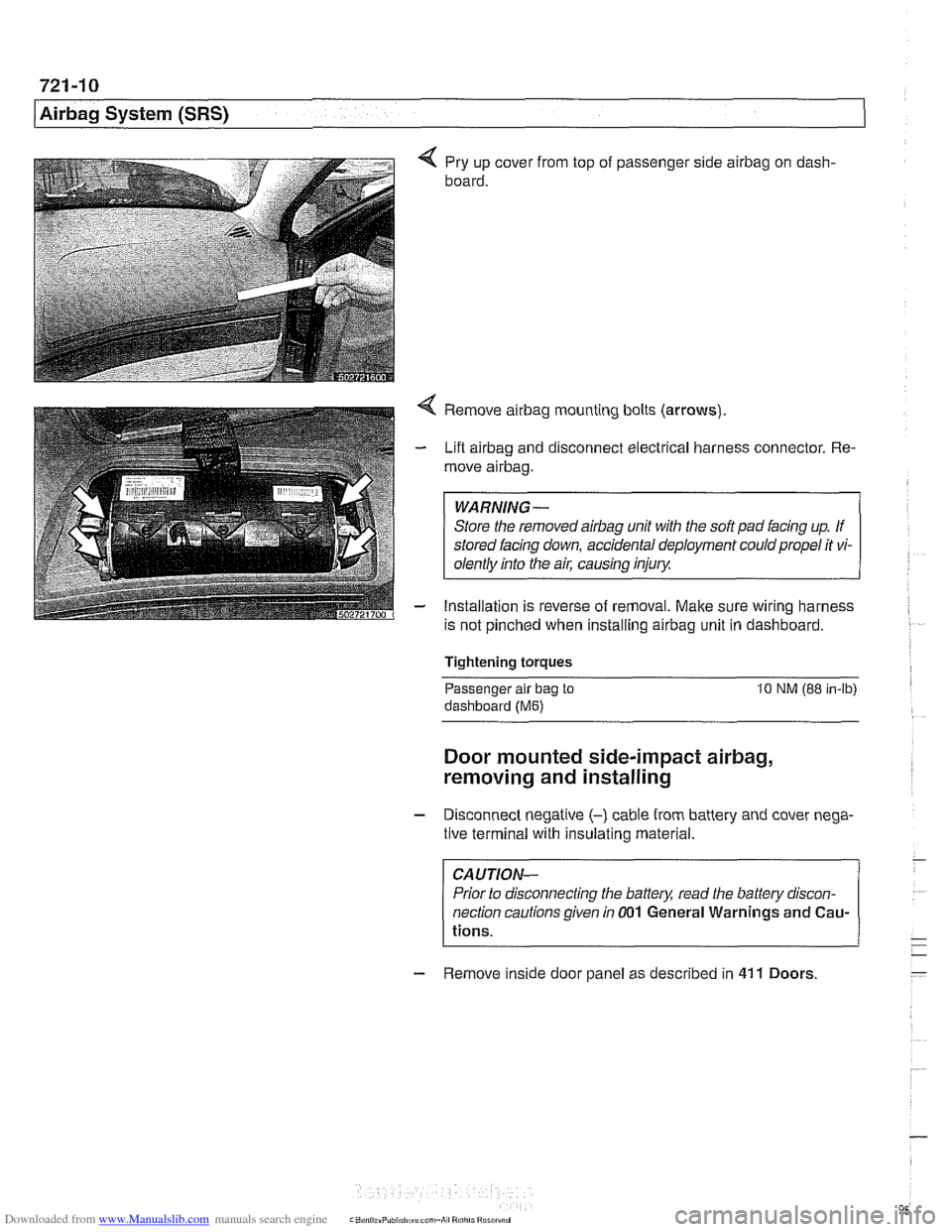
4 Pry up cover from top of passenger side airbag on dash-
board.
4 Remove airbag mounting bolts (arrows)
- Lift airbag and disconnect electrical harness connector. Re-
move
airbag.
WARNING-
Store the removed airbag unit with the soft pad facing up. If
stored facing down, accidental deployment could propel it vi-
olentlv into the
ail: causino inium
- Installation is reverse of removal. Make sure wiring harness
is not pinched when installing
airbag unit in dashboard.
Tightening torques
-
Passenger alr bag to 10 NM (88 in-lb)
dashboard (Me)
Door mounted side-impact airbag,
removing and installing
- Disconnect negatlve (-) cable from battery and cover nega-
tive terminal with insulating material.
CAUTION-
Prior to disconnecting the battea read the battery discon-
nection cautions given
in 001 General Warnings and Cau-
tions.
- Remove inside door panel as described in 41 1 Doors
Page 959 of 1002
Downloaded from www.Manualslib.com manuals search engine
721 -1 1
Airbag System (SRS)~
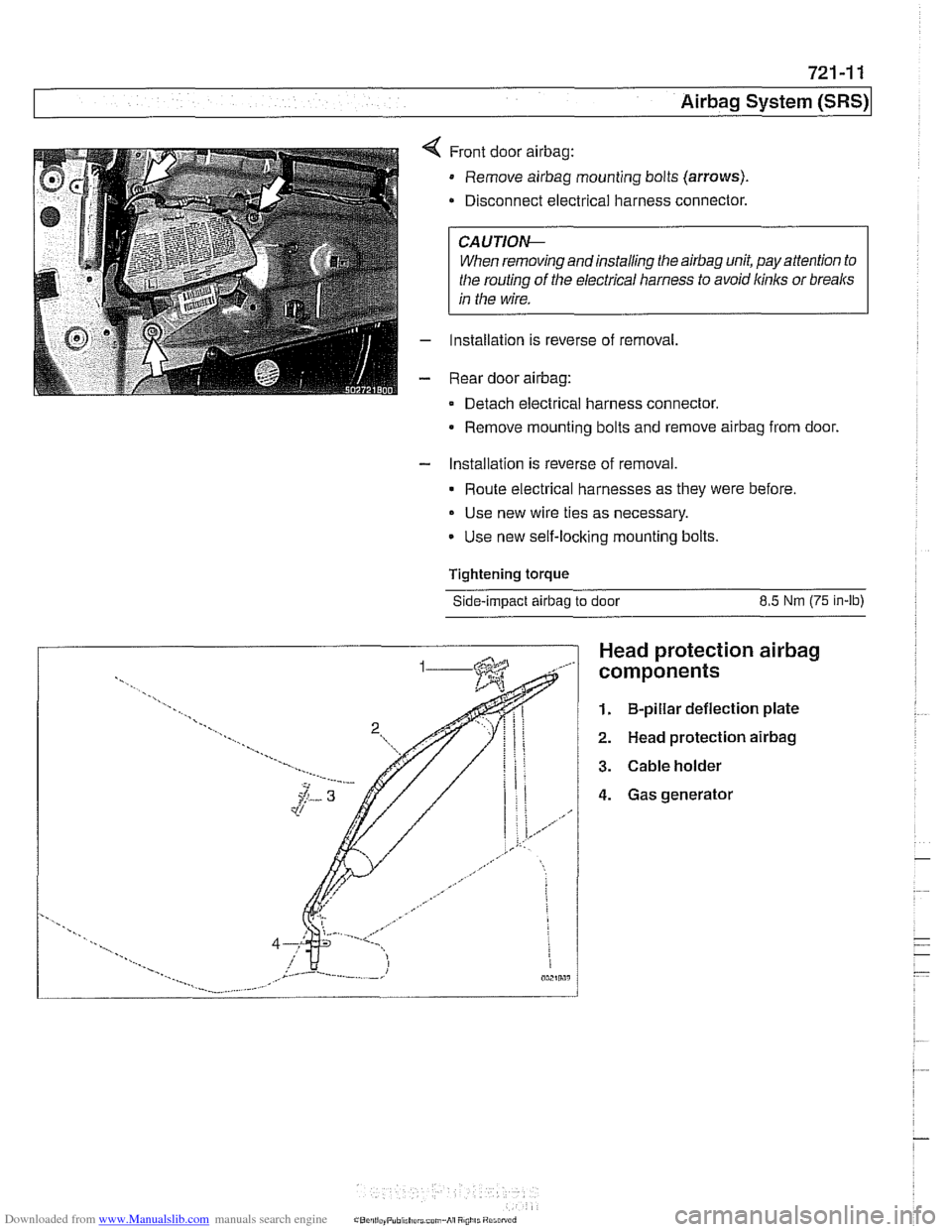
Front door airbag:
Remove airbag mounting bolts (arrows).
Disconnect electrical harness connector.
CAUTIOI\C
When removing andinstalling the airbag unit, pay attention to
the routing
of the electrical harness to avoid kinks or breaks
in the wire.
Installation is reverse of removal,
Rear door
airbag:
Detach electrical harness connector.
Remove mounting bolts and remove
airbag from door.
- Installation is reverse of removal.
Route electrical harnesses as they were before.
Use new wire ties as necessary.
Use new self-locking mounting bolts.
Tightening
torque
Side-impact airbag to door 8.5 Nm (75 in-lb)
Head protection airbag
components
1. B-pillar deflection plate
2. Head protection airbag
3. Cable holder
4. Gas generator