lock BMW 550I GRAN TURISMO 2011 Owner's Manual
[x] Cancel search | Manufacturer: BMW, Model Year: 2011, Model line: 550I GRAN TURISMO, Model: BMW 550I GRAN TURISMO 2011Pages: 297, PDF Size: 8.59 MB
Page 59 of 297
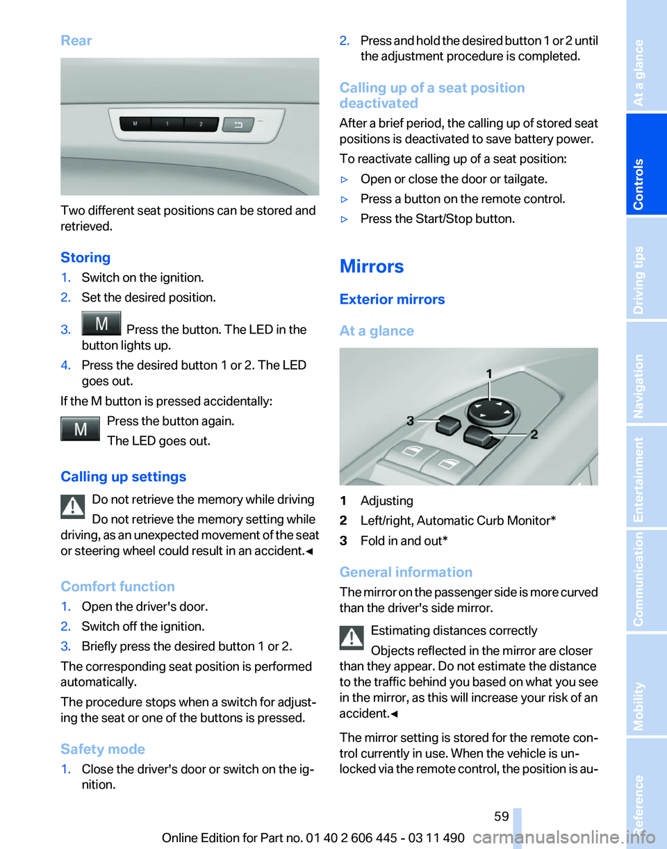
Rear
Two different seat positions can be stored and
retrieved.
Storing
1.
Switch on the ignition.
2. Set the desired position.
3. Press the button. The LED in the
button lights up.
4. Press the desired button 1 or 2. The LED
goes out.
If the M button is pressed accidentally: Press the button again.
The LED goes out.
Calling up settings Do not retrieve the memory while driving
Do not retrieve the memory setting while
driving,
as an unexpected movement of the seat
or steering wheel could result in an accident.◀
Comfort function
1. Open the driver's door.
2. Switch off the ignition.
3. Briefly press the desired button 1 or 2.
The corresponding seat position is performed
automatically.
The procedure stops when a switch for adjust‐
ing the seat or one of the buttons is pressed.
Safety mode
1. Close the driver's door or switch on the ig‐
nition. 2.
Press and hold the desired button 1 or 2 until
the adjustment procedure is completed.
Calling up of a seat position
deactivated
After
a brief period, the calling up of stored seat
positions is deactivated to save battery power.
To reactivate calling up of a seat position:
▷ Open or close the door or tailgate.
▷ Press a button on the remote control.
▷ Press the Start/Stop button.
Mirrors
Exterior mirrors
At a glance 1
Adjusting
2 Left/right, Automatic Curb Monitor*
3 Fold in and out*
General information
The
mirror on the passenger side is more curved
than the driver's side mirror.
Estimating distances correctly
Objects reflected in the mirror are closer
than they appear. Do not estimate the distance
to the traffic behind you based on what you see
in the mirror, as this will increase your risk of an
accident.◀
The mirror setting is stored for the remote con‐
trol currently in use. When the vehicle is un‐
locked via the remote control, the position is au‐ Seite 59
59Online Edition for Part no. 01 40 2 606 445 - 03 11 490
Reference Mobility Communication Entertainment Navigation Driving tips
Controls At a glance
Page 63 of 297
Backrest width*
Before
installing a child restraint fixing system in
the front passenger seat, open the backrest
width completely. Do not change the backrest
width again and do not call up a memory posi‐
tion.
Backrest width for the child seat
Before installing a child restraint fixing
system in the front passenger seat, the backrest
width must be opened completely. Do not
change the adjustment after this; otherwise, the
stability of the child seat will be reduced.◀
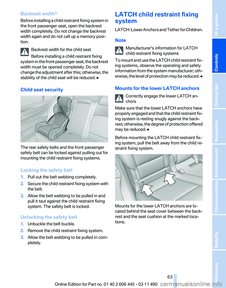
Child seat security The rear safety belts and the front passenger
safety belt can be locked against pulling out for
mounting the child restraint fixing systems.
Locking the safety belt
1.
Pull out the belt webbing completely.
2. Secure the child restraint fixing system with
the belt.
3. Allow the belt webbing to be pulled in and
pull it taut against the child restraint fixing
system. The safety belt is locked.
Unlocking the safety belt
1. Unbuckle the belt buckle.
2. Remove the child restraint fixing system.
3. Allow the belt webbing to be pulled in com‐
pletely. LATCH child restraint fixing
system
LATCH:
Lower Anchors and Tether for Children.
Note Manufacturer's information for LATCH
child restraint fixing systems
To mount and use the LATCH child restraint fix‐
ing systems, observe the operating and safety
information from the system manufacturer; oth‐
erwise, the level of protection may be reduced.◀
Mounts for the lower LATCH anchors
Correctly engage the lower LATCH an‐
chors
Make sure that the lower LATCH anchors have
properly engaged and that the child restraint fix‐
ing system is resting snugly against the back‐
rest; otherwise, the degree of protection offered
may be reduced.◀
Before mounting the LATCH child restraint fix‐
ing system, pull the belt away from the child re‐
straint fixing system. Mounts for the lower LATCH anchors are lo‐
cated behind the seat cover between the back‐
rest and the seat cushion at the marked loca‐
tions. Seite 63
63Online Edition for Part no. 01 40 2 606 445 - 03 11 490
Reference Mobility Communication Entertainment Navigation Driving tips
Controls At a glance
Page 65 of 297
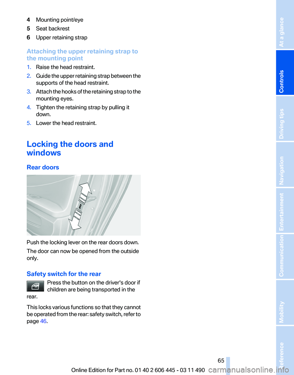
4
Mounting point/eye
5 Seat backrest
6 Upper retaining strap
Attaching the upper retaining strap to
the mounting point
1. Raise the head restraint.
2. Guide the upper retaining strap between the
supports of the head restraint.
3. Attach the hooks of the retaining strap to the
mounting eyes.
4. Tighten the retaining strap by pulling it
down.
5. Lower the head restraint.
Locking the doors and
windows
Rear doors Push the locking lever on the rear doors down.
The door can now be opened from the outside
only.
Safety switch for the rear
Press the button on the driver's door if
children are being transported in the
rear.
This
locks various functions so that they cannot
be operated from the rear: safety switch, refer to
page 46. Seite 65
65Online Edition for Part no. 01 40 2 606 445 - 03 11 490
Reference Mobility Communication Entertainment Navigation Driving tips
Controls At a glance
Page 66 of 297
Driving
Start/Stop button
The concept
Pressing the Start/Stop button
switches
the ignition on or off and
starts the engine.
The engine starts if the brake
pedal is pressed when you press
the Start/Stop button.
Ignition on
Press the Start/Stop button, and do not press on
the brake pedal at the same time.
All vehicle systems are ready for operation.
Most of the indicator and warning lamps in the
instrument cluster light up for varying lengths of
time.
To save battery power when the engine is off,
switch off the ignition and any unnecessary
electronic systems/power consumers.
The ignition switches off automatically:
▷ When the vehicle is locked, if the low beams
are switched on.
▷ Shortly before the battery is discharged
completely, so that the engine can still be
started.
▷ If the engine is switched off and the ignition
is switched on, the system automatically
switches to the radio ready state when the
door is opened if the lights are switched off
or the daytime running lights are switched
on.
Ignition off
Press the Start/Stop button again, and do not
press on the brake pedal at the same time.
All indicator lamps in the instrument cluster go
out.
To save battery power when the engine is off,
switch off the ignition and any unnecessary
electronic systems/power consumers. Transmission position P with the ignition
off
When the ignition is switched off, position P is
engaged automatically. When in an automatic
car
wash, for example, ensure that the ignition is
not switched off accidentally.◀
When the vehicle is locked using the central
locking system, the ignition switches off auto‐
matically.
Radio ready state
Activate radio ready state:
▷ When the ignition is switched off: press ON/
OFF button on the radio.
▷ When the engine is running: press START/
STOP button.
Some electronic systems/power consumers re‐
main ready for operation.
Radio ready state switches off automatically:
▷ After approx. 8 minutes.
▷ When the vehicle is locked using the central
locking system.
Starting the engine
General information Enclosed areas
Do not let the engine run in enclosed
areas; otherwise, breathing of exhaust fumes
may lead to loss of consciousness and death.
The
exhaust gases contain carbon monoxide, an
odorless and colorless but highly toxic gas.◀
Unattended vehicle
Do not leave the car unattended with the
engine running; otherwise, it presents a poten‐
tial source of danger. Seite 66
66 Online Edition for Part no. 01 40 2 606 445 - 03 11 490
Driving
Page 68 of 297
Set the parking brake and further secure
the vehicle as required
Set the parking brake firmly when parking; oth‐
erwise, the vehicle could roll. On steep upward
and
downward inclines, further secure the vehi‐
cle, for example, by turning the steering wheel in
the direction of the curb. ◀
While driving
Use while driving:
Pull the switch and hold it. The vehicle brakes
hard while the button is being pulled.
The indicator lamp lights up in red, a sig‐
nal sounds and the brake lamps light up.
Lower lamp: indicator lamp in Canadian
models
If the vehicle is braked to a speed of approx.
2 mph/3 km/h, the parking brake remains set.
Releasing Press the switch while the brake pedal is
pressed or transmission position P is en‐
gaged.
The LED and indicator lamp go out.
The parking brake is released.
Take the remote control with you
Take the remote control with you when
leaving the vehicle so that children, for example,
cannot release the parking brake.◀
Manual release
The parking brake can be released manually in
the event of a power failure or electrical fault.
Before releasing, secure the vehicle
against rolling
Before releasing the parking brake manually,
and whenever you park the vehicle with the
parking brake released, ensure that position P of
the automatic transmission is engaged. Secure the vehicle in a manner appropriate to
the inclination of the road, e.g., with a wheel
chock; otherwise, there is the danger of the ve‐
hicle rolling.◀
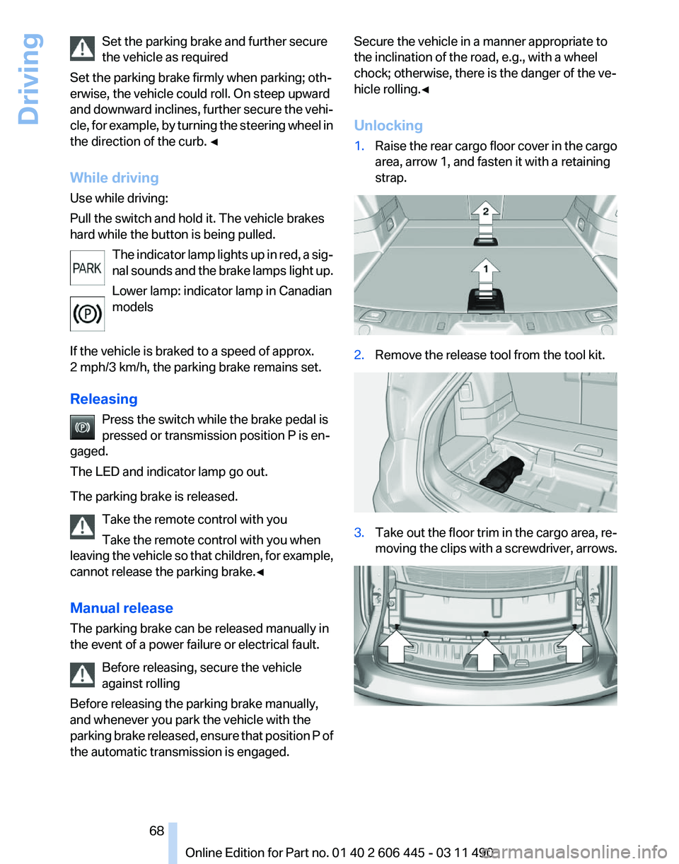
Unlocking
1.
Raise the rear cargo floor cover in the cargo
area, arrow 1, and fasten it with a retaining
strap. 2.
Remove the release tool from the tool kit. 3.
Take out the floor trim in the cargo area, re‐
moving
the clips with a screwdriver, arrows. Seite 68
68 Online Edition for Part no. 01 40 2 606 445 - 03 11 490
Driving
Page 74 of 297
When the ignition is switched off, refer to
page
66, position P is engaged automatically.
P Park
Select only when the vehicle is stationary. The
drive wheels are blocked.
P is engaged automatically:
▷ After the engine is switched off, if the car is
in
radio ready state, refer to page 66, or if the
ignition is switched off, refer to page 66, and
if position R or D is engaged.
▷ If the ignition is switched off and position N
is engaged.
▷ If the safety belt is unbuckled, the driver's
door is opened, and the brake pedal is not
pressed while the vehicle is stationary and
transmission position R or D is engaged.
Kickdown
Kickdown is used to achieve maximum driving
performance. Press on the accelerator beyond
the resistance point at the full throttle position.
Engaging the transmission position
▷ Transmission position P can only be disen‐
gaged
if the engine is running and the brake
pedal is pressed.
▷ With the vehicle stationary, press on the
brake pedal before shifting out of P or N;
otherwise, the shift command will not be
executed: shift lock.
Depress
the brake until you start driv‐
ing
To prevent the vehicle from creeping after
you select a driving position, maintain pres‐
sure on the brake pedal until you are ready
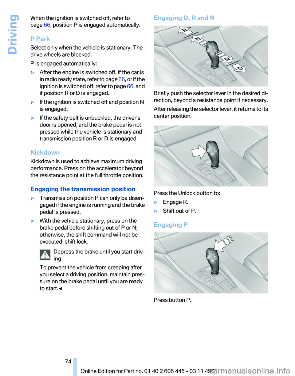
to start.◀ Engaging D, R and N
Briefly push the selector lever in the desired di‐
rection, beyond a resistance point if necessary.
After
releasing the selector lever, it returns to its
center position. Press the Unlock button to:
▷
Engage R.
▷ Shift out of P.
Engaging P Press button P.
Seite 74
74 Online Edition for Part no. 01 40 2 606 445 - 03 11 490
Driving
Page 76 of 297
Displays
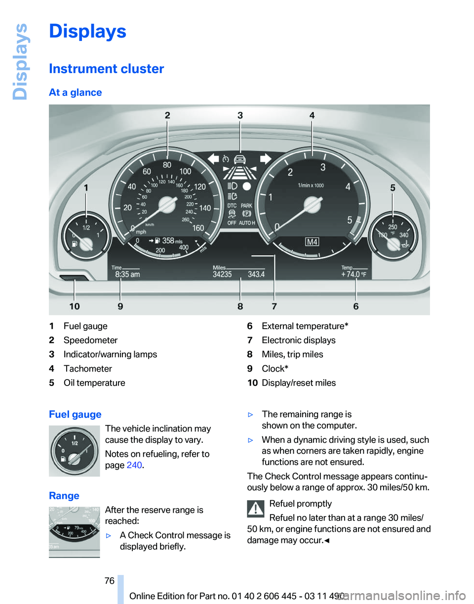
Instrument cluster
At a glance
1
Fuel gauge
2 Speedometer
3 Indicator/warning lamps
4 Tachometer
5 Oil temperature 6
External temperature*
7 Electronic displays
8 Miles, trip miles
9 Clock*
10 Display/reset miles
Fuel gauge The vehicle inclination may
cause the display to vary.
Notes on refueling, refer to
page 240.
Range After the reserve range is
reached:
▷A Check Control message is
displayed briefly. ▷
The remaining range is
shown on the computer.
▷ When a dynamic driving style is used, such
as when corners are taken rapidly, engine
functions are not ensured.
The Check Control message appears continu‐
ously below a range of approx. 30 miles/50 km.
Refuel promptly
Refuel no later than at a range 30 miles/
50
km, or engine functions are not ensured and
damage may occur.◀ Seite 76
76 Online Edition for Part no. 01 40 2 606 445 - 03 11 490
Displays
Page 85 of 297
Lamps
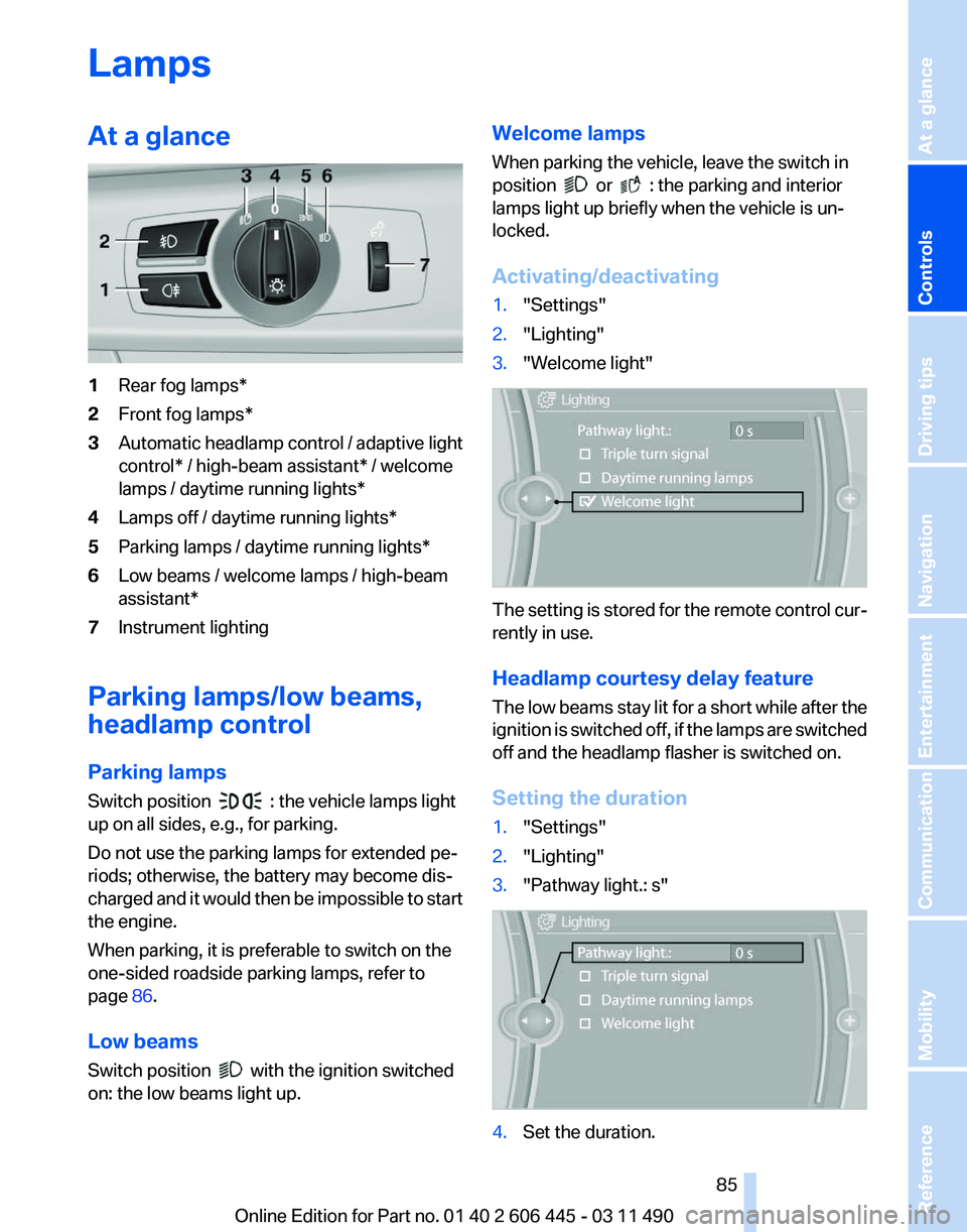
At a glance
1
Rear fog lamps*
2 Front fog lamps*
3 Automatic headlamp control / adaptive light
control* / high-beam assistant* / welcome
lamps / daytime running lights
*
4 Lamps off / daytime running lights*
5 Parking lamps / daytime running lights*
6 Low beams / welcome lamps / high-beam
assistant*
7 Instrument lighting
Parking lamps/low beams,
headlamp control
Parking lamps
Switch position : the vehicle lamps light
up on all sides, e.g., for parking.
Do not use the parking lamps for extended pe‐
riods; otherwise, the battery may become dis‐
charged
and it would then be impossible to start
the engine.
When parking, it is preferable to switch on the
one-sided roadside parking lamps, refer to
page 86.
Low beams
Switch position with the ignition switched
on: the low beams light up. Welcome lamps
When parking the vehicle, leave the switch in
position or : the parking and interior
lamps light up briefly when the vehicle is un‐
locked.
Activating/deactivating
1. "Settings"
2. "Lighting"
3. "Welcome light" The setting is stored for the remote control cur‐
rently in use.
Headlamp courtesy delay feature
The
low beams stay lit for a short while after the
ignition is switched off, if the lamps are switched
off and the headlamp flasher is switched on.
Setting the duration
1. "Settings"
2. "Lighting"
3. "Pathway light.: s" 4.
Set the duration.
Seite 85
85Online Edition for Part no. 01 40 2 606 445 - 03 11 490
Reference Mobility Communication Entertainment Navigation Driving tips
Controls At a glance
Page 89 of 297
Safety
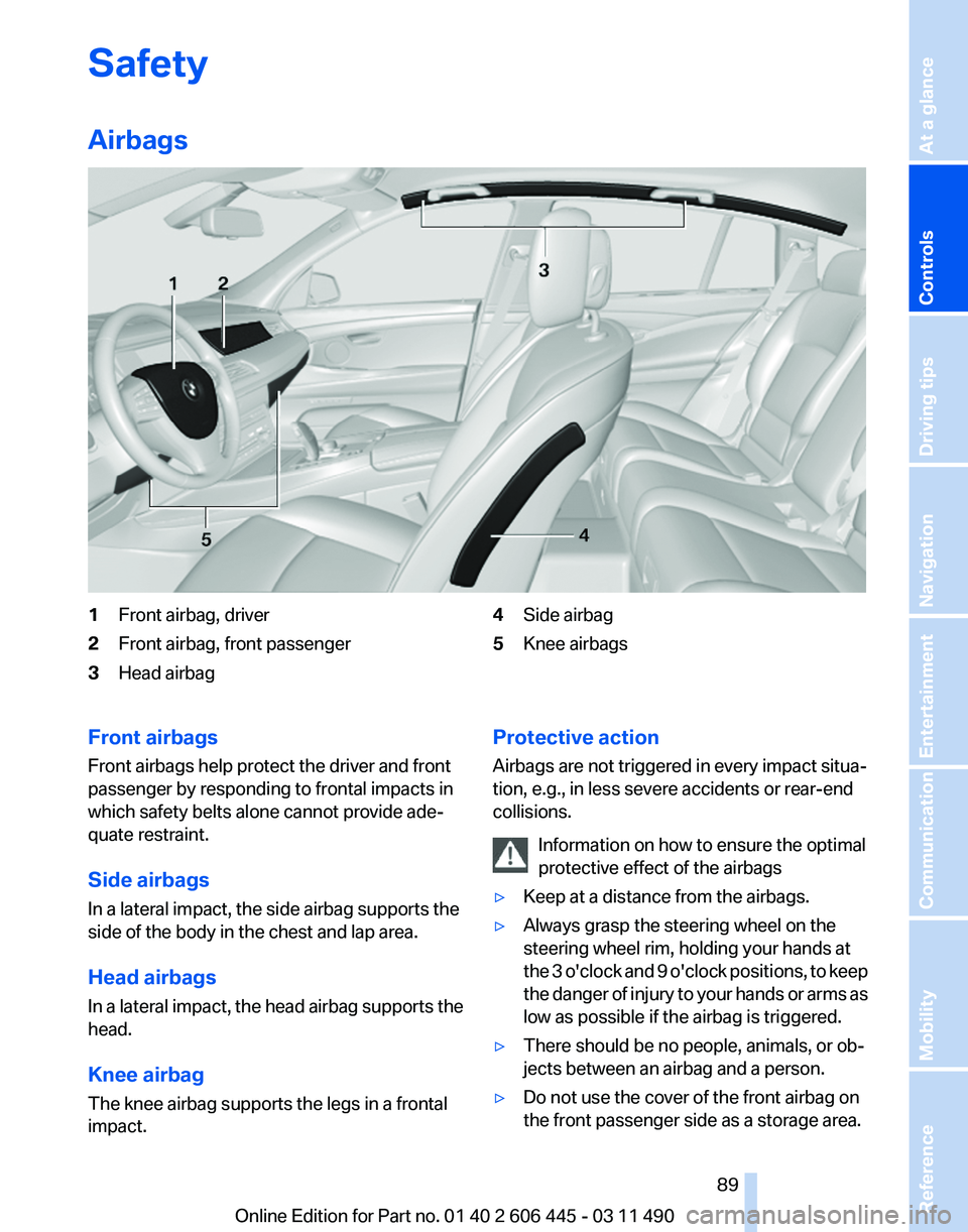
Airbags
1
Front airbag, driver
2 Front airbag, front passenger
3 Head airbag 4
Side airbag
5 Knee airbags
Front airbags
Front airbags help protect the driver and front
passenger by responding to frontal impacts in
which safety belts alone cannot provide ade‐
quate restraint.
Side airbags
In a lateral impact, the side airbag supports the
side of the body in the chest and lap area.
Head airbags
In
a lateral impact, the head airbag supports the
head.
Knee airbag
The knee airbag supports the legs in a frontal
impact. Protective action
Airbags are not triggered in every impact situa‐
tion, e.g., in less severe accidents or rear-end
collisions.
Information on how to ensure the optimal
protective effect of the airbags
▷ Keep at a distance from the airbags.
▷ Always grasp the steering wheel on the
steering wheel rim, holding your hands at
the
3 o'clock and 9 o'clock positions, to keep
the danger of injury to your hands or arms as
low as possible if the airbag is triggered.
▷ There should be no people, animals, or ob‐
jects between an airbag and a person.
▷ Do not use the cover of the front airbag on
the front passenger side as a storage area. Seite 89
89Online Edition for Part no. 01 40 2 606 445 - 03 11 490
Reference Mobility Communication Entertainment Navigation Driving tips
Controls At a glance
Page 99 of 297
Driving stability control systems
Antilock Brake System ABS
ABS
prevents locking of the wheels during brak‐
ing.
The vehicle remains steerable even during full
brake applications, thus increasing active
safety.
ABS is operational every time you start the en‐
gine.
Brake assistant
When you apply the brakes rapidly, this system
automatically produces the maximum braking
force boost. It thus helps to achieve the shortest
possible braking distance during full braking.
This system utilizes all of the benefits provided
by ABS.
Do not reduce the pressure on the brake pedal
for the duration of the full braking.
Adaptive brake assistant
In combination with the Active Cruise Control,
this system ensures that the brakes respond
even more rapidly when braking in critical situa‐
tions. Refer also to Collision warning, refer to
page 112.
Drive-off assistant
This system supports driving away on gradients.
The parking brake is not required.
1. Hold the vehicle in place with the foot brake.
2. Release the foot brake and drive away with‐
out delay.
After the foot brake is released, the vehicle is
held in place for approx. 2 seconds.
Depending on the vehicle load, the vehicle may
roll back slightly. Driving off without delay
After
releasing the foot brake, start driving
without delay, since the drive-off assistant will
not hold the vehicle in place for more than ap‐
prox. 2 seconds and the vehicle will begin rolling
back.◀
DSC Dynamic Stability
Control
The concept
DSC prevents traction loss in the driving wheels
when driving away and accelerating.
DSC also recognizes unstable vehicle condi‐
tions, such as fishtailing or nose-diving. Subject
to physical limits, DSC helps to keep the vehicle
on a steady course by reducing engine speed
and by applying brakes at individual wheels.
Adjust your driving style to the situation
An appropriate driving style is always the
responsibility of the driver.
The laws of physics cannot be repealed, even
with DSC.
Therefore, do not reduce the additional safety
margin by driving in a risky manner.◀
Deactivating DSC: DSC OFF
DSC can be deactivated. To do this, activate the
DSC OFF program.
This is performed via the Dynamic Driving Con‐
trol, refer to page 103.
Indicator/warning lamps The indicator lamp flashes: DSC con‐
trols the drive forces and brake forces.
The indicator lamp lights up: DSC has
failed. Seite 99
99Online Edition for Part no. 01 40 2 606 445 - 03 11 490
Reference Mobility Communication Entertainment Navigation Driving tips
Controls At a glance