trunk BMW 550I XDRIVE 2013 User Guide
[x] Cancel search | Manufacturer: BMW, Model Year: 2013, Model line: 550I XDRIVE, Model: BMW 550I XDRIVE 2013Pages: 246, PDF Size: 5.39 MB
Page 41 of 246
Locking
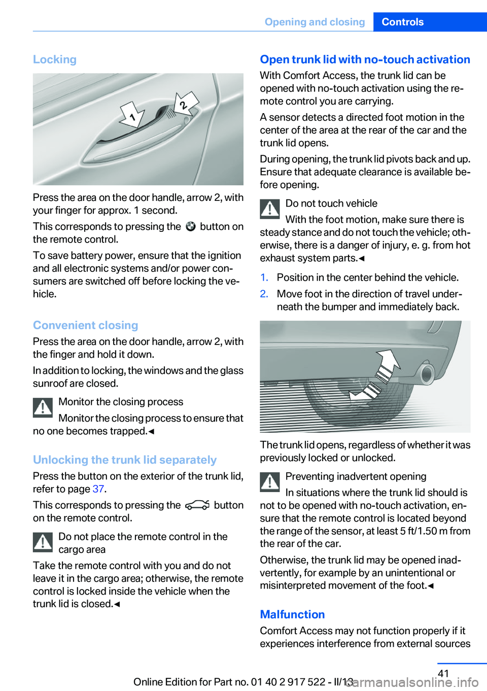
Press the area on the door handle, arrow 2, with
your finger for approx. 1 second.
This corresponds to pressing the
button on
the remote control.
To save battery power, ensure that the ignition
and all electronic systems and/or power con‐
sumers are switched off before locking the ve‐
hicle.
Convenient closing
Press the area on the door handle, arrow 2, with
the finger and hold it down.
In addition to locking, the windows and the glass
sunroof are closed.
Monitor the closing process
Monitor the closing process to ensure that
no one becomes trapped.◀
Unlocking the trunk lid separately
Press the button on the exterior of the trunk lid,
refer to page 37.
This corresponds to pressing the
button
on the remote control.
Do not place the remote control in the
cargo area
Take the remote control with you and do not
leave it in the cargo area; otherwise, the remote
control is locked inside the vehicle when the
trunk lid is closed.◀
Open trunk lid with no-touch activation
With Comfort Access, the trunk lid can be
opened with no-touch activation using the re‐
mote control you are carrying.
A sensor detects a directed foot motion in the
center of the area at the rear of the car and the
trunk lid opens.
During opening, the trunk lid pivots back and up.
Ensure that adequate clearance is available be‐
fore opening.
Do not touch vehicle
With the foot motion, make sure there is
steady stance and do not touch the vehicle; oth‐
erwise, there is a danger of injury, e. g. from hot
exhaust system parts.◀1.Position in the center behind the vehicle.2.Move foot in the direction of travel under‐
neath the bumper and immediately back.
The trunk lid opens, regardless of whether it was
previously locked or unlocked.
Preventing inadvertent opening
In situations where the trunk lid should is
not to be opened with no-touch activation, en‐
sure that the remote control is located beyond
the range of the sensor, at least 5 ft/1.50 m from
the rear of the car.
Otherwise, the trunk lid may be opened inad‐
vertently, for example by an unintentional or
misinterpreted movement of the foot.◀
Malfunction
Comfort Access may not function properly if it
experiences interference from external sources
Seite 41Opening and closingControls41
Online Edition for Part no. 01 40 2 917 522 - II/13
Page 42 of 246
such as mobile phones, metal objects, overhead
power lines, transmission towers, etc.
In this case, open or close the vehicle using the
buttons on the remote control or use the
integrated key in the door lock.
If there is a malfunction, open the trunk lid with
the remote control button or with the button on
the trunk lid.
Alarm system
The concept
The vehicle alarm system responds to:▷Opening of a door, the hood or the trunk lid.▷Movements in the vehicle.▷Changes in the vehicle tilt, e.g., during at‐
tempts to steal a wheel or when towing the
car.▷Interruptions in battery voltage.
The alarm system briefly indicates tampering:
▷By sounding an acoustic alarm.▷By switching on the hazard warning system.▷By flashing the high beams.
Arming and disarming the alarm
system
General information
When you lock or unlock the vehicle, either with
the remote control, Comfort Access or at the
door lock the alarm system is armed or disarmed
at the same time.
Door lock and armed alarm system
Unlocking via the door lock will trigger the alarm
on some country-specific versions.
In order to terminate this alarm, unlock vehicle
with the remote control or switch on the ignition,
if necessary, by emergency detection of the re‐
mote control.
Trunk lid and armed alarm system
The trunk lid can be opened even when the
alarm system is armed.
Press the button on the remote control
for approx. 1 second.
With Comfort Access the trunk lid opens with
no-touch activation, refer to page 41.
After the trunk lid is closed, it is locked and
monitored again if the doors are locked. The
hazard warning system flashes once.
In some vehicle equipment variants, the trunk lid
can only be opened using the remote control if
the vehicle was unlocked first.
Panic mode
You can trigger the alarm system if you find
yourself in a dangerous situation.
Press the button on the remote control
for at least 3 seconds.
To switch off the alarm: press any button.
Switching off the alarm▷Unlock the vehicle using the remote control.▷With Comfort Access: If you are carrying the
remote control with you, pull on the driver
side or front passenger side door handle.
Indicator lamp on the interior rear view
mirror
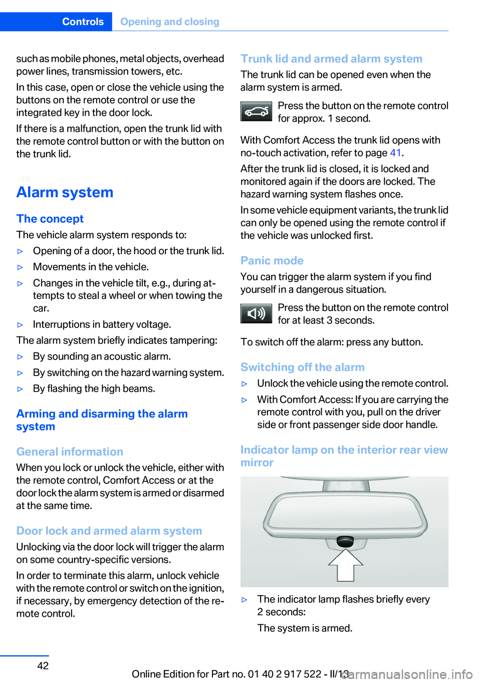
▷The indicator lamp flashes briefly every
2 seconds:
The system is armed.Seite 42ControlsOpening and closing42
Online Edition for Part no. 01 40 2 917 522 - II/13
Page 43 of 246
▷The indicator lamp flashes after locking:
The doors, hood or trunk lid is not closed
properly, but the rest of the vehicle is se‐
cured.
After 10 seconds, the indicator lamp flashes
continuously. Interior motion sensor and tilt
alarm sensor are not active.▷The indicator lamp goes out after unlocking:
The vehicle has not been tampered with.▷The indicator lamp flashes after unlocking
until the engine ignition is switched on, but
no longer than approx. 5 minutes:
An alarm has been triggered.
Tilt alarm sensor
The tilt of the vehicle is monitored.
The alarm system responds in situations such
as attempts to steal a wheel or when the car is
towed.
Interior motion sensor
The windows and glass sunroof must be closed
for the system to function properly.
Avoiding unintentional alarms
The tilt alarm sensor and interior motion sensor
can be switched off together, such as in the fol‐
lowing situations:
▷In automatic car washes.▷In duplex garages.▷During transport on car-carrying trains, at
sea or on a trailer.▷When animals are to remain in the vehicle.
Switching off the tilt alarm sensor and
interior motion sensor
Press the remote control button again
within 10 seconds as soon as the vehicle
is locked.
The indicator lamp lights up for approx. 2 sec‐
onds and then continues to flash.
The tilt alarm sensor and interior motion sensor
are switched off until the vehicle is locked again.
Power windows
General information Take the remote control with you
Take the remote control with you when
leaving the vehicle so that children, for example,
cannot operate the power windows and injure
themselves.◀
Opening
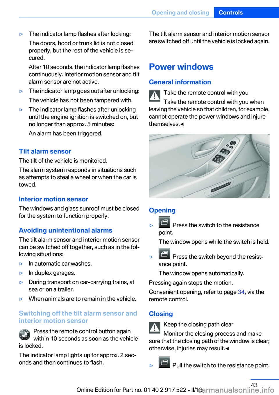
▷ Press the switch to the resistance
point.
The window opens while the switch is held.▷ Press the switch beyond the resist‐
ance point.
The window opens automatically.
Pressing again stops the motion.
Convenient opening, refer to page 34, via the
remote control.
Closing Keep the closing path clear
Monitor the closing process and make
sure that the closing path of the window is clear;
otherwise, injuries may result.◀
▷ Pull the switch to the resistance point.
Seite 43Opening and closingControls43
Online Edition for Part no. 01 40 2 917 522 - II/13
Page 55 of 246
Calling up settingsDo not retrieve the memory while driving
Do not retrieve the memory setting while
driving, as an unexpected movement of the seat
or steering wheel could result in an accident.◀
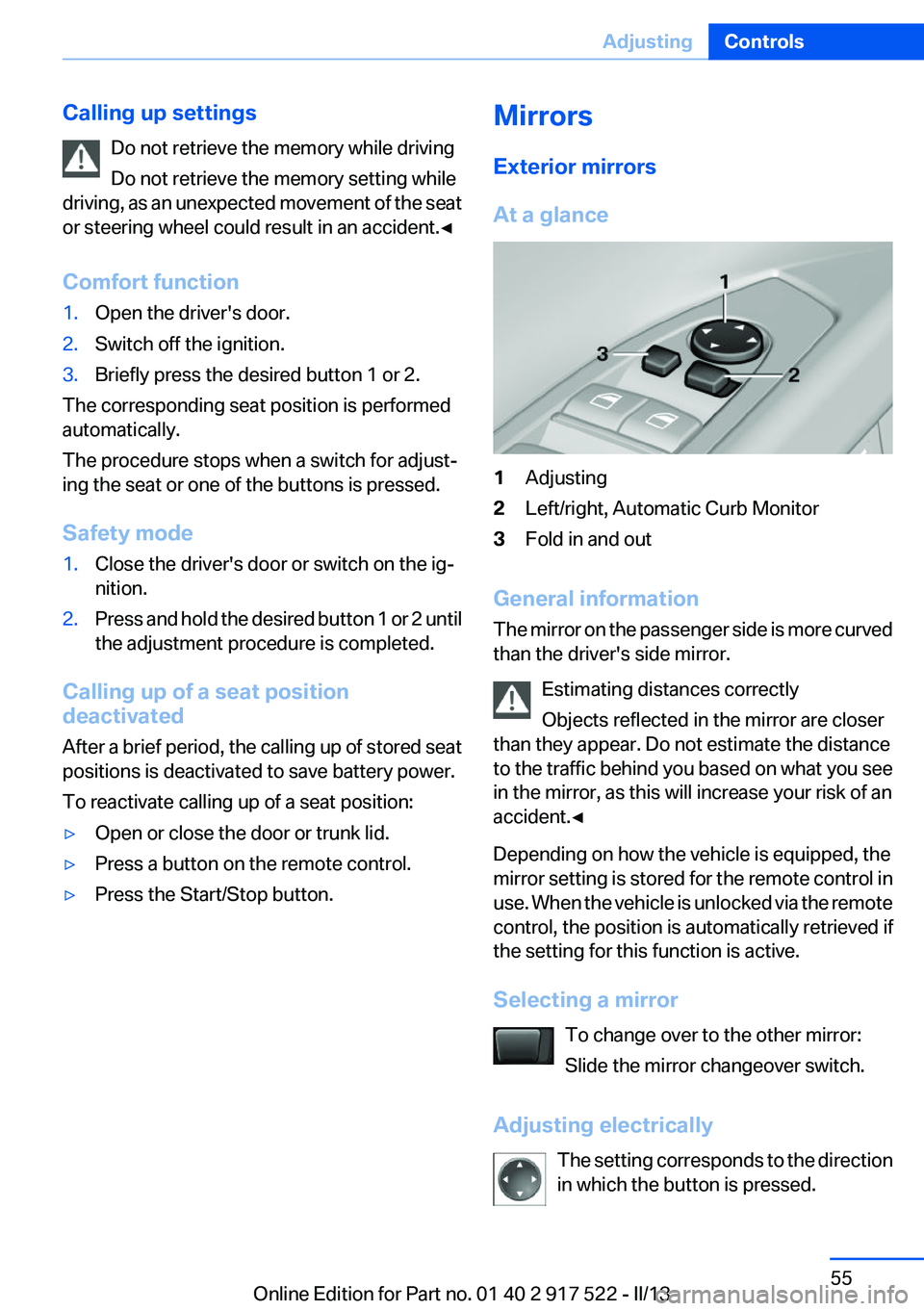
Comfort function1.Open the driver's door.2.Switch off the ignition.3.Briefly press the desired button 1 or 2.
The corresponding seat position is performed
automatically.
The procedure stops when a switch for adjust‐
ing the seat or one of the buttons is pressed.
Safety mode
1.Close the driver's door or switch on the ig‐
nition.2.Press and hold the desired button 1 or 2 until
the adjustment procedure is completed.
Calling up of a seat position
deactivated
After a brief period, the calling up of stored seat
positions is deactivated to save battery power.
To reactivate calling up of a seat position:
▷Open or close the door or trunk lid.▷Press a button on the remote control.▷Press the Start/Stop button.Mirrors
Exterior mirrors
At a glance1Adjusting2Left/right, Automatic Curb Monitor3Fold in and out
General information
The mirror on the passenger side is more curved
than the driver's side mirror.
Estimating distances correctly
Objects reflected in the mirror are closer
than they appear. Do not estimate the distance
to the traffic behind you based on what you see
in the mirror, as this will increase your risk of an
accident.◀
Depending on how the vehicle is equipped, the
mirror setting is stored for the remote control in
use. When the vehicle is unlocked via the remote
control, the position is automatically retrieved if
the setting for this function is active.
Selecting a mirror To change over to the other mirror:
Slide the mirror changeover switch.
Adjusting electrically The setting corresponds to the direction
in which the button is pressed.
Seite 55AdjustingControls55
Online Edition for Part no. 01 40 2 917 522 - II/13
Page 137 of 246
At a glance
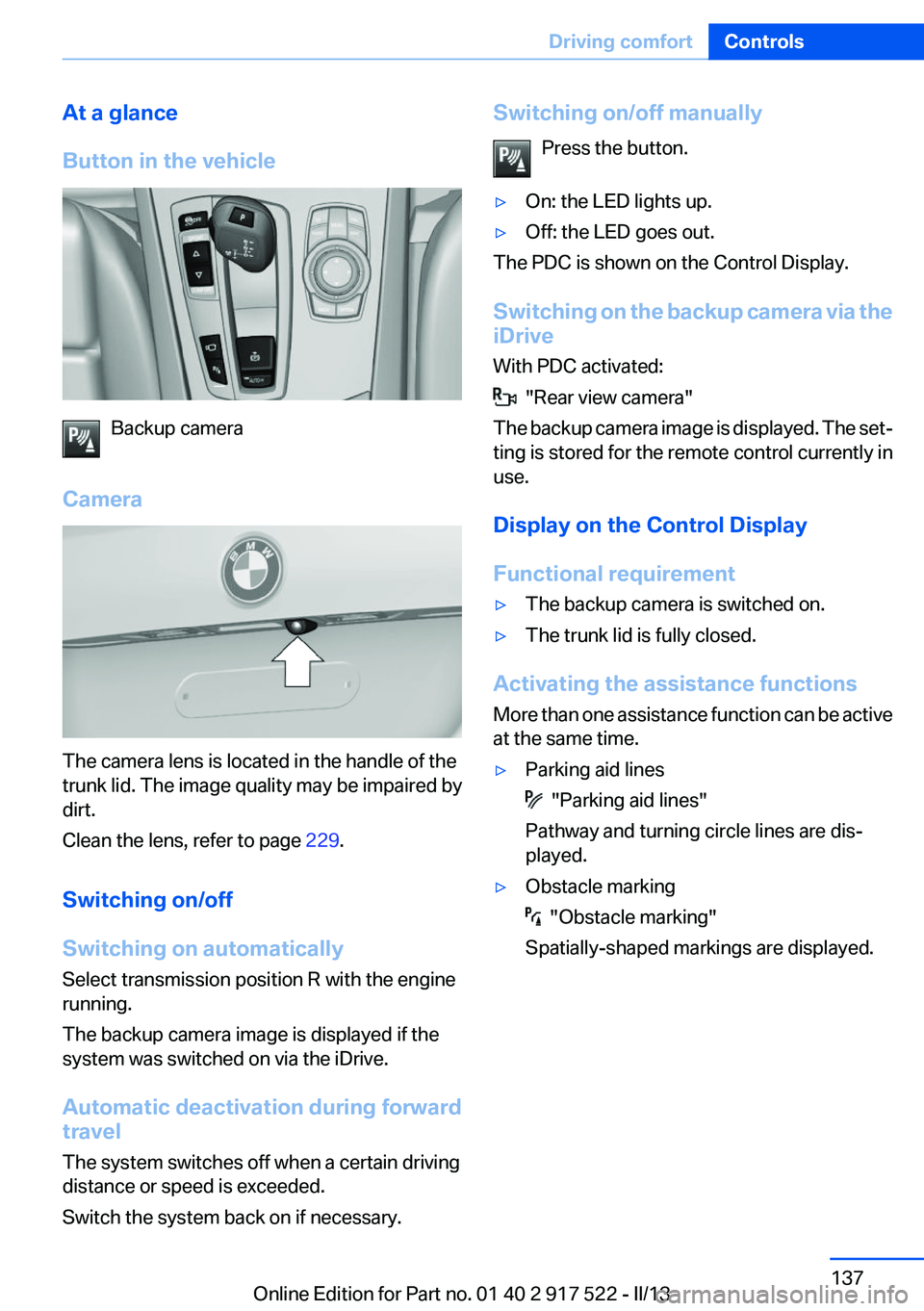
Button in the vehicle
Backup camera
Camera
The camera lens is located in the handle of the
trunk lid. The image quality may be impaired by
dirt.
Clean the lens, refer to page 229.
Switching on/off
Switching on automatically
Select transmission position R with the engine
running.
The backup camera image is displayed if the
system was switched on via the iDrive.
Automatic deactivation during forward
travel
The system switches off when a certain driving
distance or speed is exceeded.
Switch the system back on if necessary.
Switching on/off manually
Press the button.▷On: the LED lights up.▷Off: the LED goes out.
The PDC is shown on the Control Display.
Switching on the backup camera via the
iDrive
With PDC activated:
"Rear view camera"
The backup camera image is displayed. The set‐
ting is stored for the remote control currently in
use.
Display on the Control Display
Functional requirement
▷The backup camera is switched on.▷The trunk lid is fully closed.
Activating the assistance functions
More than one assistance function can be active
at the same time.
▷Parking aid lines
"Parking aid lines"
Pathway and turning circle lines are dis‐
played.
▷Obstacle marking
"Obstacle marking"
Spatially-shaped markings are displayed.
Seite 137Driving comfortControls137
Online Edition for Part no. 01 40 2 917 522 - II/13
Page 141 of 246
The pathway line is dependent on the cur‐
rent steering angle and is continuously ad‐
justed with the steering wheel movement.
"Parking aid lines"
Turning circle and pathway lines are displayed.
System limits
Top View cannot be used in the following situa‐
tions:
▷With a door open.▷With the trunk lid open.▷With an exterior mirror folded in.▷In poor light.
A Check Control message is displayed in some
of these situations.
Side View
The concept
Side View provides an early look at cross traffic
at blind driveways and intersections. Road users
concealed by obstacles to the left and right of
the vehicle can only be detected relatively late
from the driver's seat. To improve visibility, two
cameras in the front of the vehicle record the
traffic situation on each side.
Notes
The images from both cameras are shown si‐
multaneously on the Control Display.
Check the traffic situation as well
Check the traffic situation around the ve‐
hicle on blind driveways and intersections with
your own eyes. Otherwise, an accident could re‐
sult from road users or objects located outside
the picture area of the Side View cameras.◀
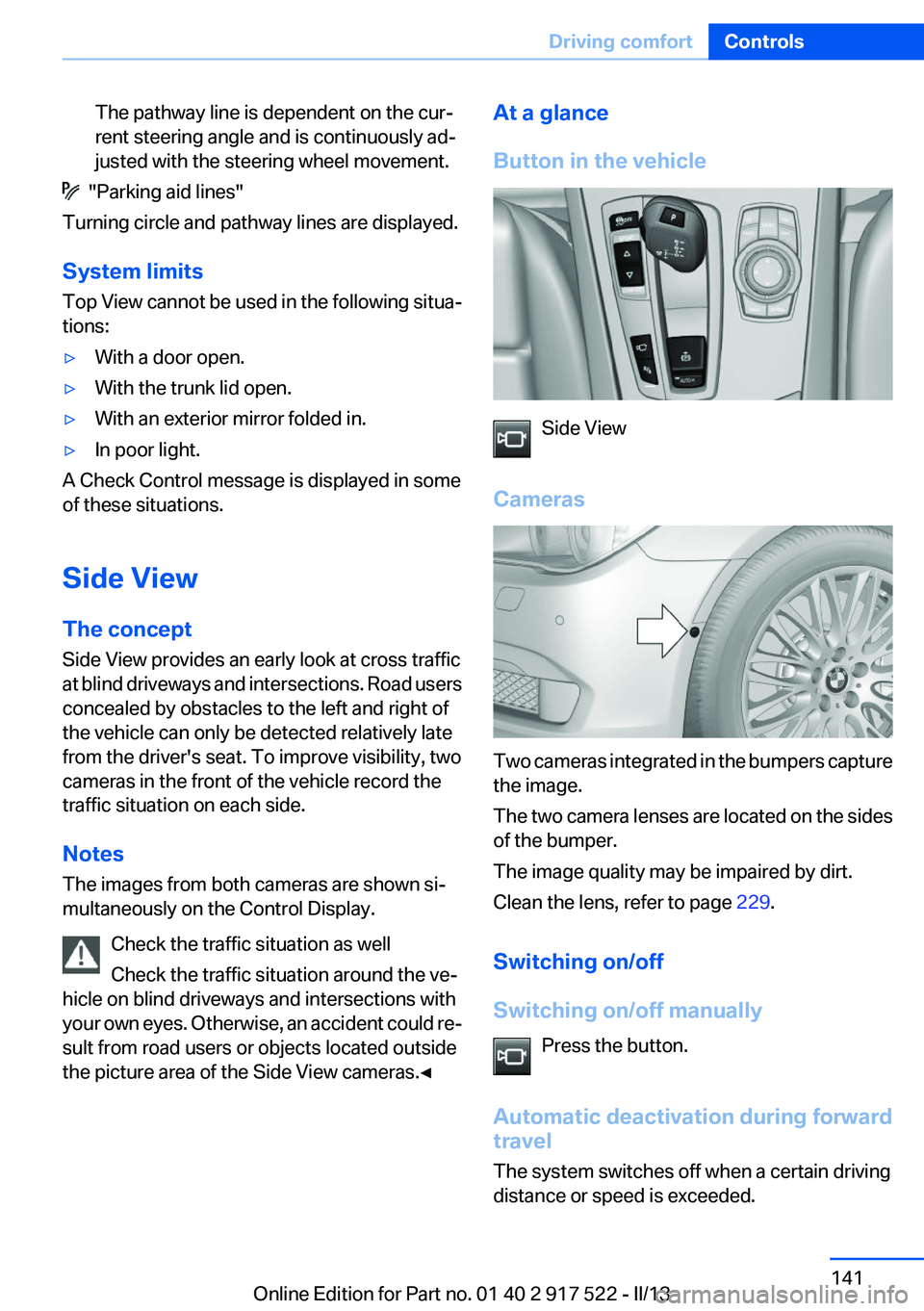
At a glance
Button in the vehicle
Side View
Cameras
Two cameras integrated in the bumpers capture
the image.
The two camera lenses are located on the sides
of the bumper.
The image quality may be impaired by dirt.
Clean the lens, refer to page 229.
Switching on/off
Switching on/off manually Press the button.
Automatic deactivation during forward
travel
The system switches off when a certain driving
distance or speed is exceeded.
Seite 141Driving comfortControls141
Online Edition for Part no. 01 40 2 917 522 - II/13
Page 165 of 246
Driver's side
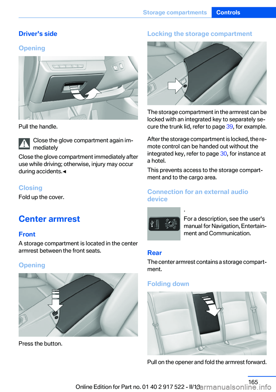
Opening
Pull the handle. Close the glove compartment again im‐
mediately
Close the glove compartment immediately after
use while driving; otherwise, injury may occur
during accidents.◀
Closing
Fold up the cover.
Center armrest
Front
A storage compartment is located in the center
armrest between the front seats.
Opening
Press the button.
Locking the storage compartment
The storage compartment in the armrest can be
locked with an integrated key to separately se‐
cure the trunk lid, refer to page 39, for example.
After the storage compartment is locked, the re‐
mote control can be handed out without the
integrated key, refer to page 30, for instance at
a hotel.
This prevents access to the storage compart‐
ment and to the cargo area.
Connection for an external audio
device
.
For a description, see the user's
manual for Navigation, Entertain‐
ment and Communication.
Rear
The center armrest contains a storage compart‐
ment.
Folding down
Pull on the opener and fold the armrest forward.
Seite 165Storage compartmentsControls165
Online Edition for Part no. 01 40 2 917 522 - II/13
Page 167 of 246
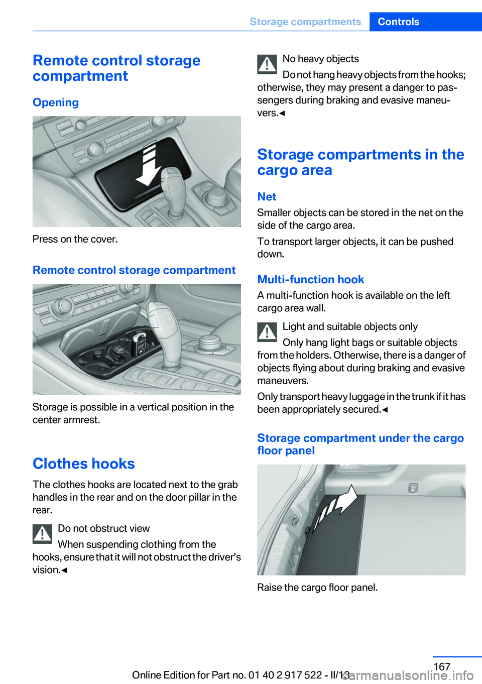
Remote control storage
compartment
Opening
Press on the cover.
Remote control storage compartment
Storage is possible in a vertical position in the
center armrest.
Clothes hooks
The clothes hooks are located next to the grab
handles in the rear and on the door pillar in the
rear.
Do not obstruct view
When suspending clothing from the
hooks, ensure that it will not obstruct the driver's
vision.◀
No heavy objects
Do not hang heavy objects from the hooks;
otherwise, they may present a danger to pas‐
sengers during braking and evasive maneu‐
vers.◀
Storage compartments in the
cargo area
Net
Smaller objects can be stored in the net on the
side of the cargo area.
To transport larger objects, it can be pushed
down.
Multi-function hook
A multi-function hook is available on the left
cargo area wall.
Light and suitable objects only
Only hang light bags or suitable objects
from the holders. Otherwise, there is a danger of
objects flying about during braking and evasive
maneuvers.
Only transport heavy luggage in the trunk if it has
been appropriately secured.◀
Storage compartment under the cargo
floor panel
Raise the cargo floor panel.
Seite 167Storage compartmentsControls167
Online Edition for Part no. 01 40 2 917 522 - II/13
Page 172 of 246
Things to remember when drivingVehicle equipment
All standard, country-specific and optional
equipment that is offered in the model series is
described in this chapter. Therefore, equipment
is also described that is not available in a vehicle,
e. g., because of the selected optional equip‐
ment or country variant. This also applies for
safety-related functions and systems.
Breaking-in period
General information
Moving parts need to be broken in to adjust to
each other.
The following instructions will help achieve a
long vehicle life and good economy.
Engine and differential
Always obey the official speed limit.
Up to 1,200 miles/2,000 km
Do not exceed the maximum engine and road
speed:▷For gasoline engine, 4,500 rpm and
100 mph/160 km/h.
Avoid full load or kickdown under all circum‐
stances.
From 1,200 miles/2,000 km
The engine and vehicle speed can gradually be
increased.
Tires
Due to technical factors associated with their
manufacture, tires do not achieve their full trac‐
tion potential until after an initial breaking-in pe‐
riod.
Drive conservatively for the first
200 miles/300 km.
Brake system
Brakes require an initial break-in period of ap‐
prox. 300 miles/500 km to achieve optimized
contact and wear patterns between brake discs
and brake pads. Drive moderately during this
break-in period.
Clutch
The function of the clutch reaches its optimal
level only after a distance driven of approx.
300 miles/500 km. During this break-in period,
engage the clutch gently.
Following part replacement
The same breaking in procedures should be ob‐
served if any of the components mentioned
above have to be renewed in the course of the
vehicle's operating life.
General driving notes
Closing the trunk lid Drive with the trunk lid closed
Only drive with the tailgate closed; other‐
wise, in the event of an accident or braking or
evasive maneuvers, passengers or other road
users may be injured or the vehicle may be dam‐
aged. In addition, exhaust fumes may enter the
passenger compartment.◀
If driving with the tailgate open cannot be
avoided:▷Close all windows and the glass sunroof.▷Greatly increase the blower speed.▷Drive moderately.Seite 172Driving tipsThings to remember when driving172
Online Edition for Part no. 01 40 2 917 522 - II/13
Page 175 of 246
LoadingVehicle equipment
All standard, country-specific and optional
equipment that is offered in the model series is
described in this chapter. Therefore, equipment
is also described that is not available in a vehicle,
e. g., because of the selected optional equip‐
ment or country variant. This also applies for
safety-related functions and systems.
Hints Overloading the vehicle
To avoid exceeding the approved carrying
capacity of the tires, never overload the vehicle.
Overloading can lead to overheating and in‐
creases the rate at which damage develops in‐
side the tires. This could result in a sudden loss
of tire inflation pressure.◀
No fluids in the trunk
Make sure that fluids do not leak into the
trunk; otherwise, the vehicle may be damaged. ◀
Determining the load limit1.Locate the following statement on your ve‐
hicle’s placard:▷The combined weight of occupants and
cargo should never exceed XXX kg or
YYY lbs. Otherwise, damage to the ve‐hicle and unstable driving situations may
result.2.Determine the combined weight of the
driver and passengers that will be riding in
your vehicle.3.Subtract the combined weight of the driver
and passengers from XXX kilograms or YYY
pounds.4.The resulting figure equals the available
amount of cargo and luggage load capacity.
For example, if the YYY amount equals
1,000 lbs and there will be four 150 lbs pas‐
sengers in your vehicle, the amount of avail‐
able cargo and luggage load capacity is
400 lbs: 1,000 lbs minus 600 lbs = 400 lbs.5.Determine the combined weight of luggage
and cargo being loaded on the vehicle. That
weight may not safely exceed the available
cargo and luggage load capacity calculated
in Step 4.
Load
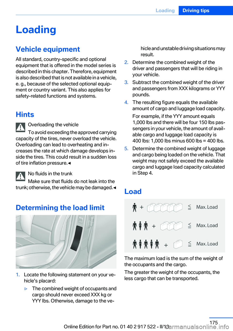
The maximum load is the sum of the weight of
the occupants and the cargo.
The greater the weight of the occupants, the
less cargo that can be transported.
Seite 175LoadingDriving tips175
Online Edition for Part no. 01 40 2 917 522 - II/13