BMW 550I XDRIVE GT 2011 F07 Owner's Manual
Manufacturer: BMW, Model Year: 2011, Model line: 550I XDRIVE GT, Model: BMW 550I XDRIVE GT 2011 F07Pages: 297, PDF Size: 8.59 MB
Page 121 of 297
Their colored steps match the markings of the
PDC. This simplifies estimation of the distance
to the object shown.
Activating the assistance functions
More
than one assistance function can be active
at the same time.
Showing the parking aid lines "Parking aid lines"
Pathway and turning circle lines are displayed.
Showing the obstacle marking "Obstacle marking"
Spatially-shaped markings are displayed.
Display on the Control Display
Switching on the backup camera via
iDrive
With PDC activated: "Rear view camera"
The
backup camera image is displayed. The set‐
ting is stored for the remote control currently in
use.
Brightness
With the backup camera switched on:
1. Select the symbol.
2. Turn the controller until the desired setting
is reached and press the controller.
Contrast
With the backup camera switched on:
1. Select the symbol.
2. Turn the controller until the desired setting
is reached and press the controller. Camera
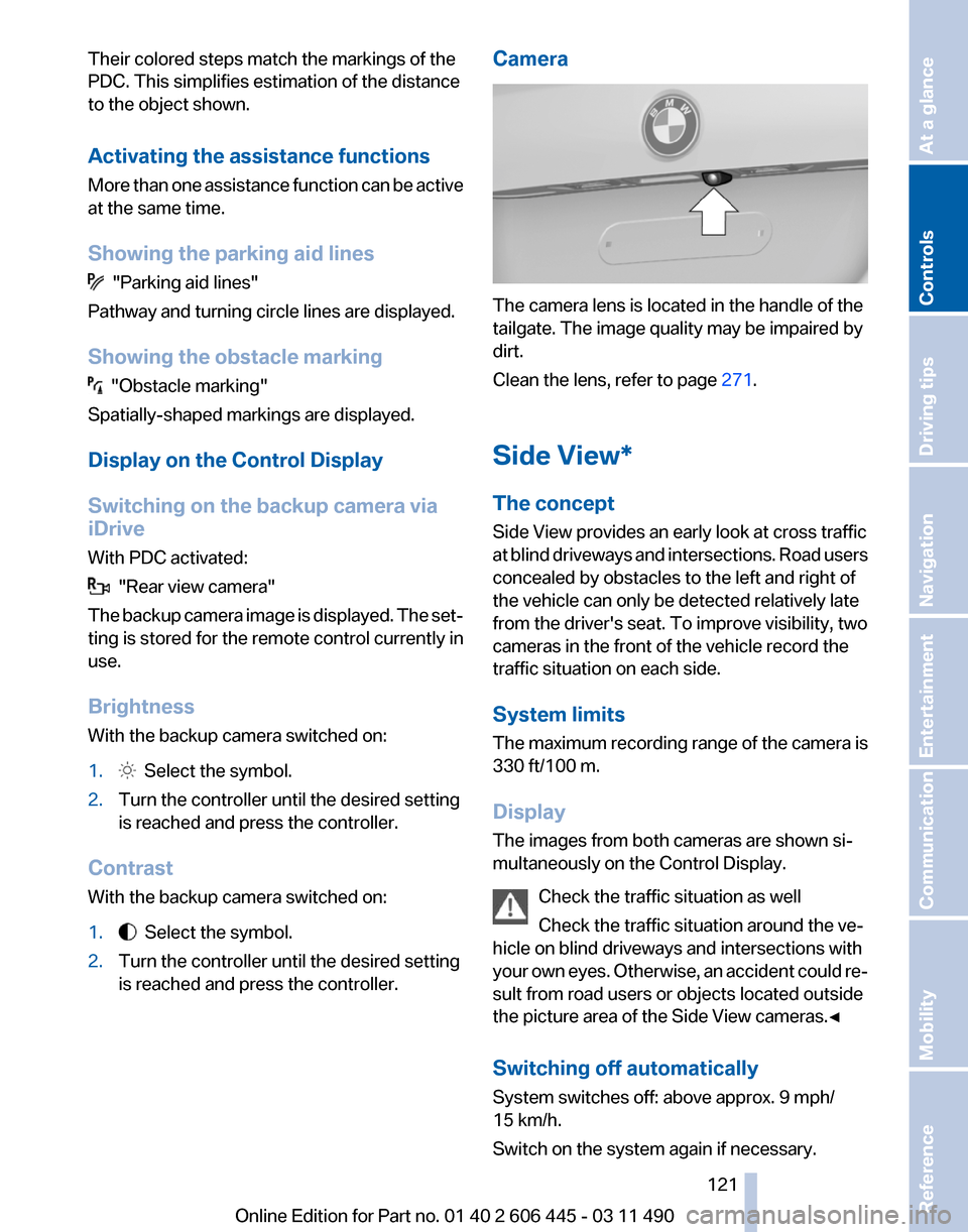
The camera lens is located in the handle of the
tailgate. The image quality may be impaired by
dirt.
Clean the lens, refer to page
271.
Side View*
The concept
Side View provides an early look at cross traffic
at
blind driveways and intersections. Road users
concealed by obstacles to the left and right of
the vehicle can only be detected relatively late
from the driver's seat. To improve visibility, two
cameras in the front of the vehicle record the
traffic situation on each side.
System limits
The maximum recording range of the camera is
330 ft/100 m.
Display
The images from both cameras are shown si‐
multaneously on the Control Display.
Check the traffic situation as well
Check the traffic situation around the ve‐
hicle on blind driveways and intersections with
your own eyes. Otherwise, an accident could re‐
sult from road users or objects located outside
the picture area of the Side View cameras.◀
Switching off automatically
System switches off: above approx. 9 mph/
15 km/h.
Switch on the system again if necessary. Seite 121
121Online Edition for Part no. 01 40 2 606 445 - 03 11 490
Reference Mobility Communication Entertainment Navigation Driving tips
Controls At a glance
Page 122 of 297
Switching on/off manually
Press the button.
Display on the Control Display
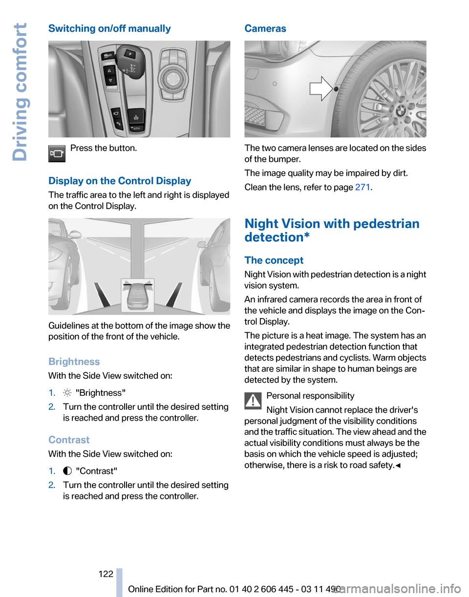
The traffic area to the left and right is displayed
on the Control Display. Guidelines at the bottom of the image show the
position of the front of the vehicle.
Brightness
With the Side View switched on:
1.
"Brightness"
2. Turn the controller until the desired setting
is reached and press the controller.
Contrast
With the Side View switched on:
1. "Contrast"
2. Turn the controller until the desired setting
is reached and press the controller. Cameras
The two camera lenses are located on the sides
of the bumper.
The image quality may be impaired by dirt.
Clean the lens, refer to page
271.
Night Vision with pedestrian
detection*
The concept
Night
Vision with pedestrian detection is a night
vision system.
An infrared camera records the area in front of
the vehicle and displays the image on the Con‐
trol Display.
The picture is a heat image. The system has an
integrated pedestrian detection function that
detects pedestrians and cyclists. Warm objects
that are similar in shape to human beings are
detected by the system.
Personal responsibility
Night Vision cannot replace the driver's
personal judgment of the visibility conditions
and the traffic situation. The view ahead and the
actual visibility conditions must always be the
basis on which the vehicle speed is adjusted;
otherwise, there is a risk to road safety.◀ Seite 122
122 Online Edition for Part no. 01 40 2 606 445 - 03 11 490
Driving comfort
Page 123 of 297
Heat image
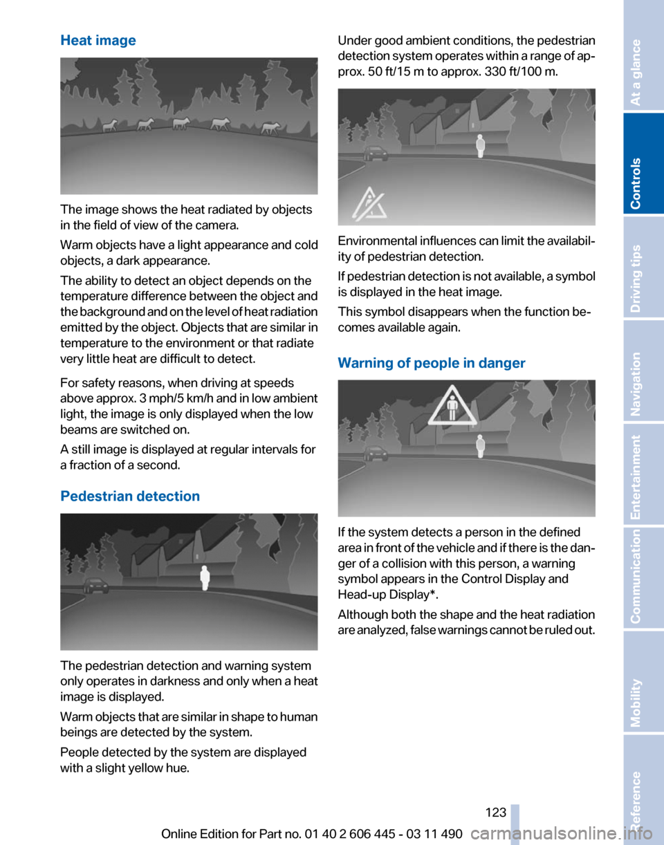
The image shows the heat radiated by objects
in the field of view of the camera.
Warm objects have a light appearance and cold
objects, a dark appearance.
The ability to detect an object depends on the
temperature
difference between the object and
the background and on the level of heat radiation
emitted by the object. Objects that are similar in
temperature to the environment or that radiate
very little heat are difficult to detect.
For safety reasons, when driving at speeds
above approx. 3 mph/5 km/h and in low ambient
light, the image is only displayed when the low
beams are switched on.
A still image is displayed at regular intervals for
a fraction of a second.
Pedestrian detection The pedestrian detection and warning system
only
operates in darkness and only when a heat
image is displayed.
Warm objects that are similar in shape to human
beings are detected by the system.
People detected by the system are displayed
with a slight yellow hue. Under good ambient conditions, the pedestrian
detection
system operates within a range of ap‐
prox. 50 ft/15 m to approx. 330 ft/100 m. Environmental influences can limit the availabil‐
ity of pedestrian detection.
If
pedestrian detection is not available, a symbol
is displayed in the heat image.
This symbol disappears when the function be‐
comes available again.
Warning of people in danger If the system detects a person in the defined
area
in front of the vehicle and if there is the dan‐
ger of a collision with this person, a warning
symbol appears in the Control Display and
Head-up Display*.
Although both the shape and the heat radiation
are analyzed, false warnings cannot be ruled out.
Seite 123
123Online Edition for Part no. 01 40 2 606 445 - 03 11 490
Reference Mobility Communication Entertainment Navigation Driving tips
Controls At a glance
Page 124 of 297
Warning area in front of the vehicle
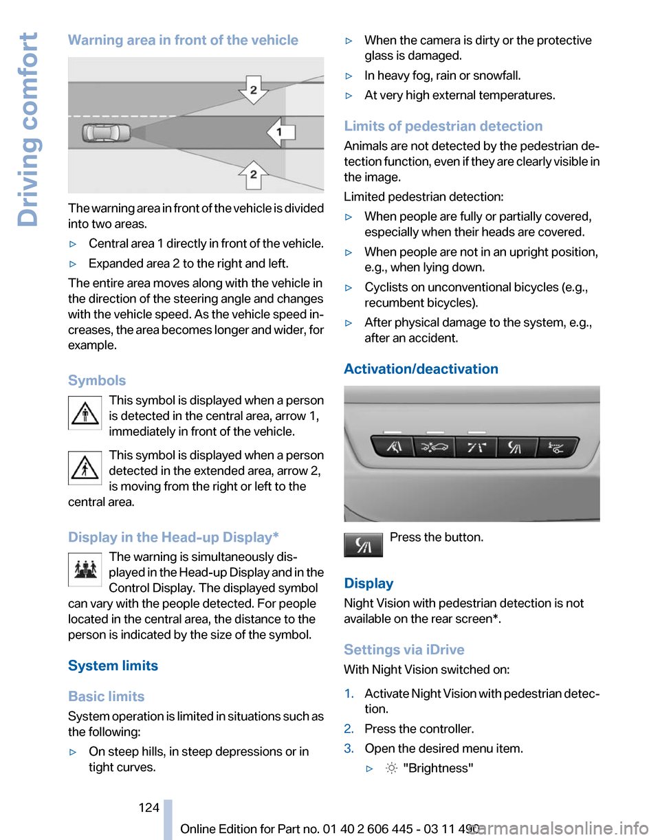
The warning area in front of the vehicle is divided
into two areas.
▷
Central area 1 directly in front of the vehicle.
▷ Expanded area 2 to the right and left.
The entire area moves along with the vehicle in
the direction of the steering angle and changes
with
the vehicle speed. As the vehicle speed in‐
creases, the area becomes longer and wider, for
example.
Symbols
This symbol is displayed when a person
is detected in the central area, arrow 1,
immediately in front of the vehicle.
This symbol is displayed when a person
detected in the extended area, arrow 2,
is moving from the right or left to the
central area.
Display in the Head-up Display*
The warning is simultaneously dis‐
played in the Head-up Display and in the
Control Display. The displayed symbol
can vary with the people detected. For people
located in the central area, the distance to the
person is indicated by the size of the symbol.
System limits
Basic limits
System operation is limited in situations such as
the following:
▷ On steep hills, in steep depressions or in
tight curves. ▷
When the camera is dirty or the protective
glass is damaged.
▷ In heavy fog, rain or snowfall.
▷ At very high external temperatures.
Limits of pedestrian detection
Animals are not detected by the pedestrian de‐
tection
function, even if they are clearly visible in
the image.
Limited pedestrian detection:
▷ When people are fully or partially covered,
especially when their heads are covered.
▷ When people are not in an upright position,
e.g., when lying down.
▷ Cyclists on unconventional bicycles (e.g.,
recumbent bicycles).
▷ After physical damage to the system, e.g.,
after an accident.
Activation/deactivation Press the button.
Display
Night Vision with pedestrian detection is not
available on the
rear screen*.
Settings via iDrive
With Night Vision switched on:
1. Activate Night Vision with pedestrian detec‐
tion.
2. Press the controller.
3. Open the desired menu item.
▷ "Brightness" Seite 124
124 Online Edition for Part no. 01 40 2 606 445 - 03 11 490
Driving comfort
Page 125 of 297
▷ "Contrast"
▷ "Pedestrian detection"
The settings are stored for the remote control
currently in use.
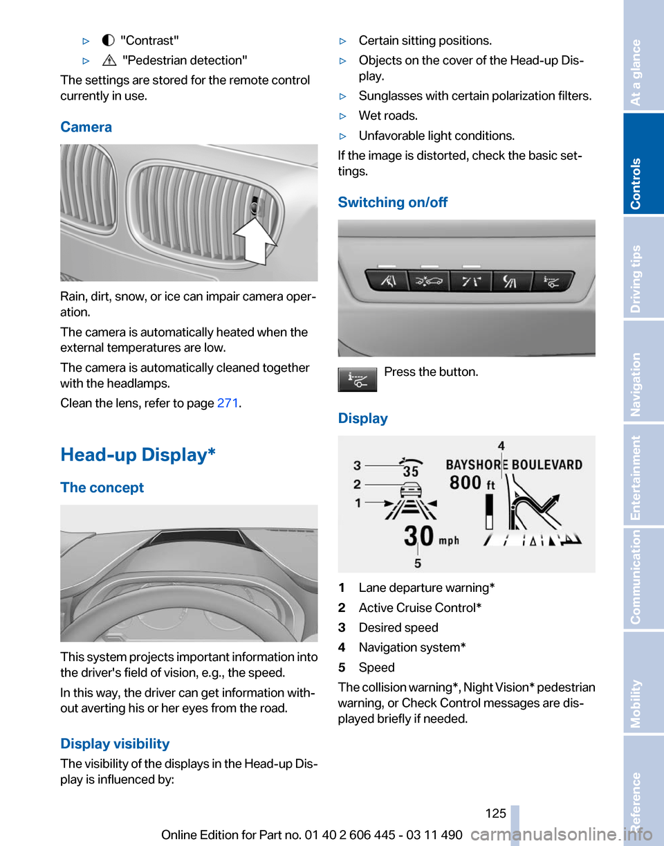
Camera Rain, dirt, snow, or ice can impair camera oper‐
ation.
The camera is automatically heated when the
external temperatures are low.
The camera is automatically cleaned together
with the headlamps.
Clean the lens, refer to page
271.
Head-up Display
*
The concept This system projects important information into
the driver's field of vision, e.g., the speed.
In this way, the driver can get information with‐
out averting his or her eyes from the road.
Display visibility
The
visibility of the displays in the Head-up Dis‐
play is influenced by: ▷
Certain sitting positions.
▷ Objects on the cover of the Head-up Dis‐
play.
▷ Sunglasses with certain polarization filters.
▷ Wet roads.
▷ Unfavorable light conditions.
If the image is distorted, check the basic set‐
tings.
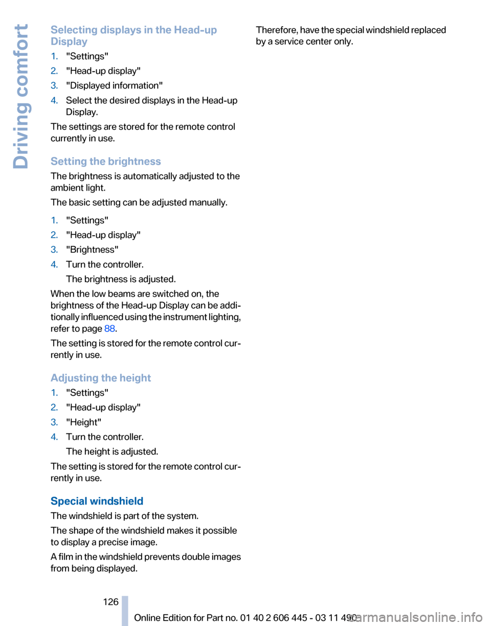
Switching on/off Press the button.
Display 1
Lane departure warning*
2 Active Cruise Control*
3 Desired speed
4 Navigation system*
5 Speed
The collision warning*, Night Vision* pedestrian
warning, or Check Control messages are dis‐
played briefly if needed. Seite 125
125Online Edition for Part no. 01 40 2 606 445 - 03 11 490
Reference Mobility Communication Entertainment Navigation Driving tips
Controls At a glance
Page 126 of 297
Selecting displays in the Head-up
Display
1.
"Settings"
2. "Head-up display"
3. "Displayed information"
4. Select the desired displays in the Head-up
Display.
The settings are stored for the remote control
currently in use.
Setting the brightness
The brightness is automatically adjusted to the
ambient light.
The basic setting can be adjusted manually.
1. "Settings"
2. "Head-up display"
3. "Brightness"
4. Turn the controller.
The brightness is adjusted.
When the low beams are switched on, the
brightness of the Head-up Display can be addi‐
tionally influenced using the instrument lighting,
refer to page 88.
The setting is stored for the remote control cur‐
rently in use.
Adjusting the height
1. "Settings"
2. "Head-up display"
3. "Height"
4. Turn the controller.
The height is adjusted.
The setting is stored for the remote control cur‐
rently in use.
Special windshield
The windshield is part of the system.
The shape of the windshield makes it possible
to display a precise image.
A
film in the windshield prevents double images
from being displayed. Therefore, have the special windshield replaced
by a service center only.
Seite 126
126 Online Edition for Part no. 01 40 2 606 445 - 03 11 490
Driving comfort
Page 127 of 297
Climate control
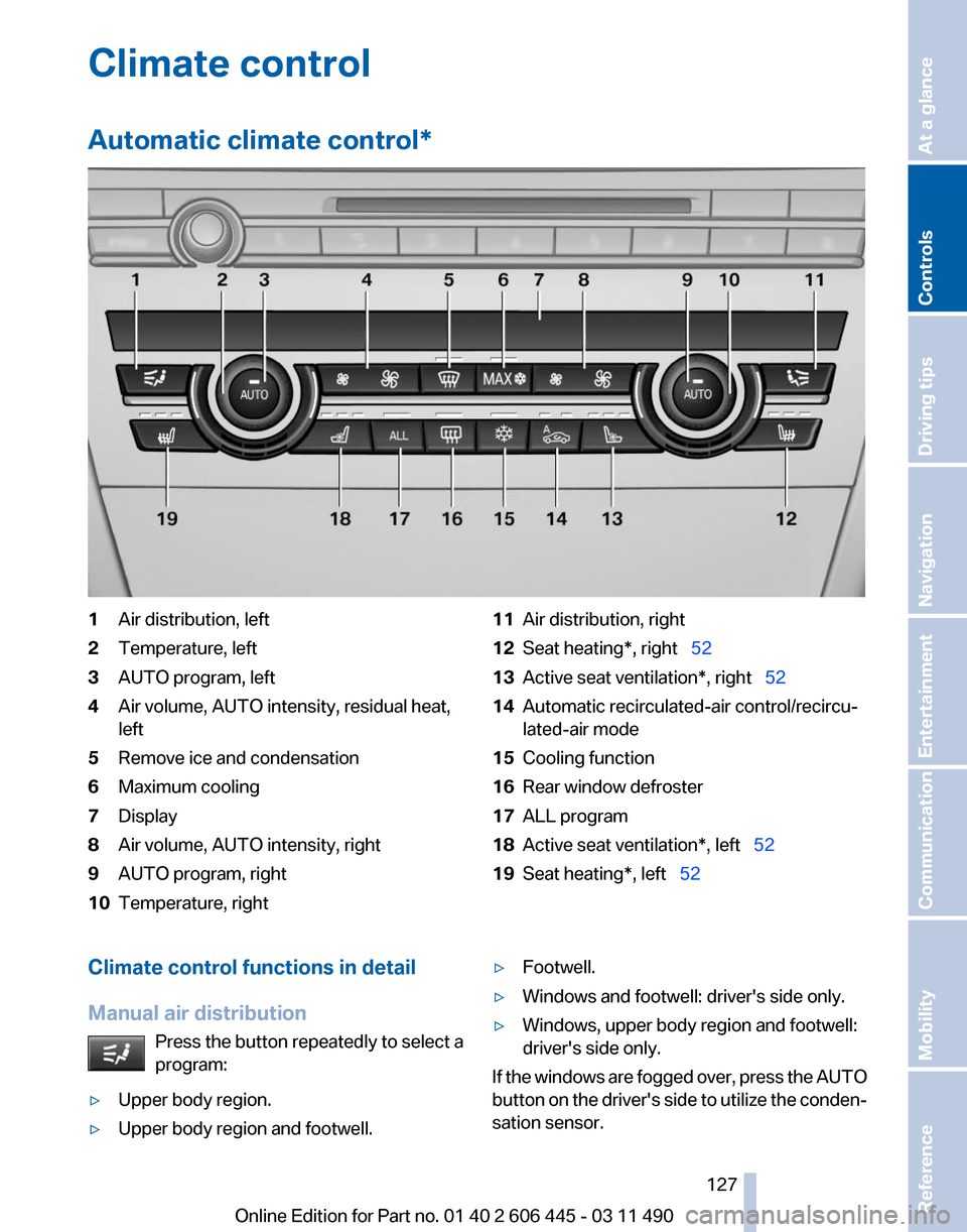
Automatic climate control
*1
Air distribution, left
2 Temperature, left
3 AUTO program, left
4 Air volume, AUTO intensity, residual heat,
left
5 Remove ice and condensation
6 Maximum cooling
7 Display
8 Air volume, AUTO intensity, right
9 AUTO program, right
10 Temperature, right 11
Air distribution, right
12 Seat heating*, right 52
13 Active seat ventilation*, right 52
14 Automatic recirculated-air control/recircu‐
lated-air mode
15 Cooling function
16 Rear window defroster
17 ALL program
18 Active seat ventilation*, left 52
19 Seat heating*, left 52
Climate control functions in detail
Manual air distribution Press the button repeatedly to select a
program:
▷ Upper body region.
▷ Upper body region and footwell. ▷
Footwell.
▷ Windows and footwell: driver's side only.
▷ Windows, upper body region and footwell:
driver's side only.
If the windows are fogged over, press the AUTO
button
on the driver's side to utilize the conden‐
sation sensor.
Seite 127
127Online Edition for Part no. 01 40 2 606 445 - 03 11 490
Reference Mobility Communication Entertainment Navigation Driving tips
Controls At a glance
Page 128 of 297
Temperature
Turn the wheel to set the desired
temperature.
The automatic climate control achieves this
temperature as quickly as possible, if necessary
with the maximum cooling or heating capacity,
and then keeps it constant.
Avoid rapidly switching between different tem‐
perature settings. The automatic climate control
will not have sufficient time to adjust the set
temperature.
AUTO program Press the button.
Air volume, air distribution, and tem‐
perature are controlled automatically.
Depending on the selected temperature, AUTO
intensity, and outside influences, the air is di‐
rected to the windshield, side windows, upper
body, and into the footwell.
The cooling function, refer to page 129, is
switched on automatically with the AUTO pro‐
gram.
At the same time, a condensation sensor con‐
trols the program so as to prevent window con‐
densation as much as possible.
Intensity of the AUTO program
With the AUTO program switched on, automatic
control of the air volume and air distribution can
be adjusted.
Press the left or right side of the button:
decrease or increase the intensity.
The selected intensity is shown on the display
of the automatic climate control.
Air volume, manual
To be able to manually adjust the air volume,
switch off the AUTO program first. Press the left or right side of the button:
decrease or increase air volume. The selected air volume is shown on the display
of the automatic climate control.
The air volume of the automatic climate control
may be reduced automatically to save battery
power.
Defrosting windows and removing
condensation
Press the button.
Ice and condensation are quickly re‐
moved from the windshield and the front side
windows.
The air volume can be adjusted when the pro‐
gram is active.
If the windows are fogged over, additionally
switch on the cooling function or press the
AUTO
button to utilize the condensation sensor.
Maximum cooling Press the button.
The system is set to the lowest tem‐
perature, maximum air volume and recirculated-
air mode.
Air flows out of the vents for the upper body re‐
gion. Open them for this purpose.
Air is cooled as quickly as possible:
▷ At an external temperature of approx. 32 ℉/
0 ℃.
▷ When the engine is running.
The air volume can be adjusted when the pro‐
gram is active.
Automatic recirculated-air control/
recirculated-air mode
You can respond to unpleasant odors or pollu‐
tants in the immediate environment by tempo‐
rarily suspending the supply of outside air. The
system
then recirculates the air currently within
the vehicle.
Press the button repeatedly to select
an operating mode:
▷ LEDs off: outside air flows in continuously. Seite 128
128 Online Edition for Part no. 01 40 2 606 445 - 03 11 490
Climate control
Page 129 of 297
▷
Left LED on, automatic recirculated-air con‐
trol: a sensor detects pollutants in the out‐
side air and controls the shut-off automati‐
cally.
▷ Right LED on, recirculated-air mode: the
supply of outside air into the vehicle is per‐
manently blocked.
If the windows are fogged over, switch off the
recirculated-air mode and press the AUTO but‐
ton on the driver's side to utilize the condensa‐
tion sensor. Make sure that air can flow onto the
windshield.
Continuous recirculated-air mode
The recirculated-air mode should not be
used for an extended period of time, as the air
quality inside the vehicle deteriorates steadily.◀
Cooling function
The passenger compartment can only be
cooled with the engine running.
Press the button.
The air is cooled and dehumidified and
– depending on the temperature setting –
warmed again.
Depending on the weather, the windshield may
fog up briefly when the engine is started.
The cooling function is switched on automati‐
cally with the AUTO program.
When using the automatic climate control, con‐
densation water, refer to page 148, develops
that exits underneath the vehicle.
Rear window defroster
Press the button.
The rear window defroster switches off
automatically after a certain period of time.
ALL program
Press the button.
The current settings on the driver's side
for temperature, air volume, air distribution, and
AUTO program are transferred to the front pas‐
senger side and to the left and right rear*. The program is switched off if the settings on
the front passenger side or in the rear* are
changed.
Residual heat
The
heat stored in the engine is used to heat the
interior.
Functional requirement
▷ Up to 20 minutes after the engine has been
switched off.
▷ Warm engine.
▷ The battery is sufficiently charged.
▷ External temperature below 77 ℉/25 ℃.
Switching on
1. Switch off the ignition.
2. Press the right side of the button on
the driver's side. is shown on the display of the automatic cli‐
mate control.
The
interior temperature, air volume and air dis‐
tribution can be adjusted with the ignition
switched on.
Switching off
At the lowest fan speed, press the left side of the
button on the driver's side. on the display of the automatic climate control
goes out.
Switching the system on/off
Switching off
▷ Complete system:
At the lowest fan speed, press the
left
side of the button on the driver's
side. ▷
On the front passenger side:
At the lowest fan speed, press the
left side of the button on the front
passenger side. Seite 129
129Online Edition for Part no. 01 40 2 606 445 - 03 11 490
Reference Mobility Communication Entertainment Navigation Driving tips
Controls At a glance
Page 130 of 297
Switching on
Press any button.
Microfilter/activated-charcoal filter
The microfilter removes dust and pollen from
the incoming air.
The activated-charcoal filter removes gaseous
pollutants from the outside air that enters the
vehicle.
This combined filter should be replaced during
scheduled
maintenance of your vehicle., refer to
page 256
Ventilation
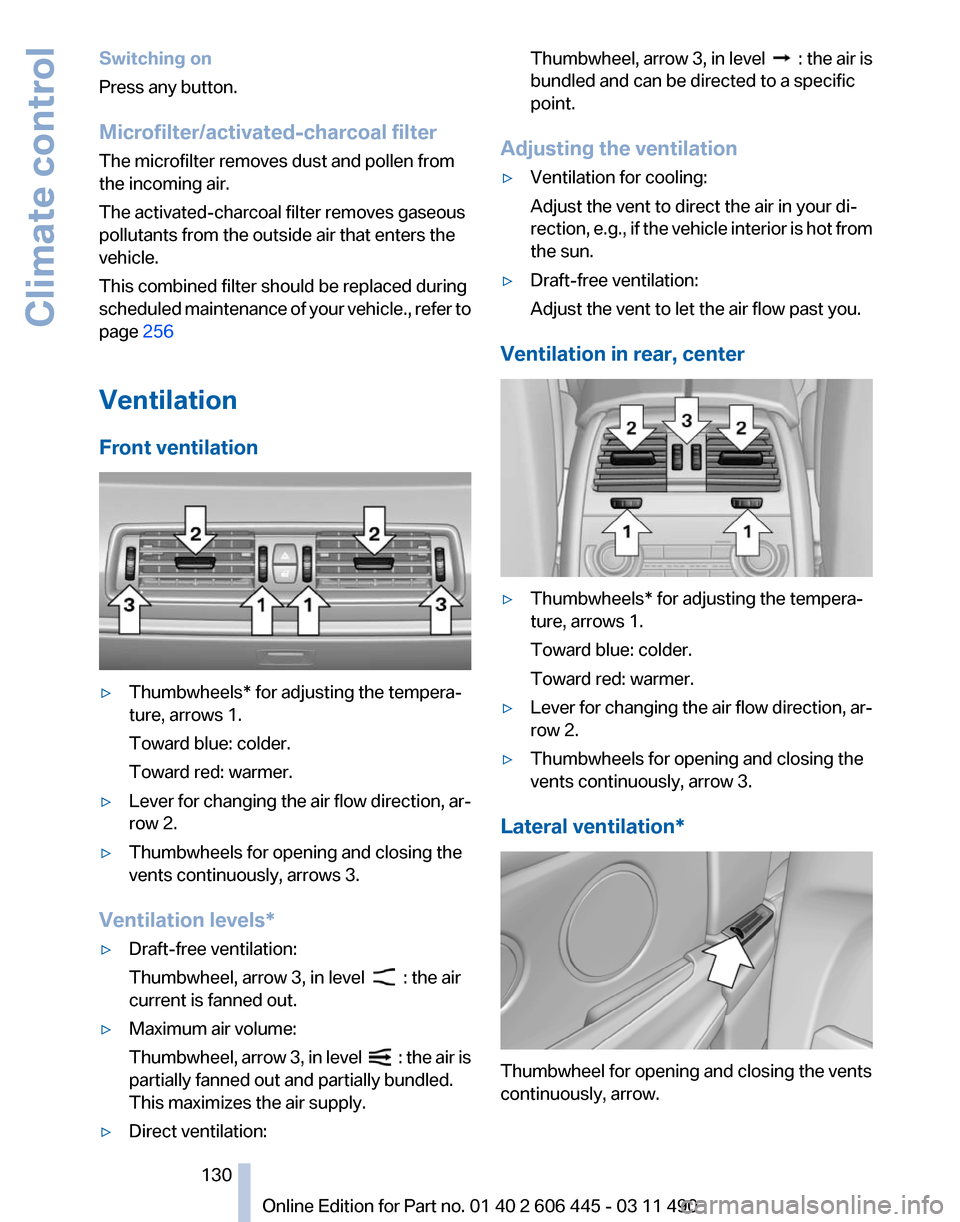
Front ventilation ▷
Thumbwheels* for adjusting the tempera‐
ture, arrows 1.
Toward blue: colder.
Toward red: warmer.
▷ Lever for changing the air flow direction, ar‐
row 2.
▷ Thumbwheels for opening and closing the
vents continuously, arrows 3.
Ventilation levels*
▷ Draft-free ventilation:
Thumbwheel, arrow 3, in level : the air
current is fanned out.
▷ Maximum air volume:
Thumbwheel,
arrow 3, in level : the air is
partially fanned out and partially bundled.
This maximizes the air supply.
▷ Direct ventilation: Thumbwheel, arrow 3, in level :
the air is
bundled and can be directed to a specific
point.
Adjusting the ventilation
▷ Ventilation for cooling:
Adjust the vent to direct the air in your di‐
rection,
e.g., if the vehicle interior is hot from
the sun.
▷ Draft-free ventilation:
Adjust the vent to let the air flow past you.
Ventilation in rear, center ▷
Thumbwheels* for adjusting the tempera‐
ture, arrows 1.
Toward blue: colder.
Toward red: warmer.
▷ Lever for changing the air flow direction, ar‐
row 2.
▷ Thumbwheels for opening and closing the
vents continuously, arrow 3.
Lateral ventilation* Thumbwheel for opening and closing the vents
continuously, arrow.
Seite 130
130 Online Edition for Part no. 01 40 2 606 445 - 03 11 490
Climate control