ECU BMW 6 SERIES 2009 Owners Manual
[x] Cancel search | Manufacturer: BMW, Model Year: 2009, Model line: 6 SERIES, Model: BMW 6 SERIES 2009Pages: 272, PDF Size: 9.16 MB
Page 3 of 272
650iOwner's Manual for Vehicle
Congratulations, and thank you for choosing a BMW.
Thorough familiarity with your vehicle will provide you with
enhanced control and security when you drive it. We therefore
have this request:
Please take the time to read this Owner's Manual and familiarize
yourself with the information that we have compiled for you
before starting off in your new vehicle. It contains important data
and instructions intended to assist you in gaining maximum use
and satisfaction from your BMW's unique range of technical fea-
tures. The manual also contains information on maintenance
designed to enhance operating safety and contribute to main-
taining the value of your BMW throughout an extended service
life.
This manual is supplemented by a Service and Warranty Informa-
tion Booklet for US models or a Warranty and Service Guide
Booklet for Canadian models.
We wish you an enjoyable driving experience.
BMW AG
Page 32 of 272
Opening and closing
30
Opening and closing
Keys/remote control
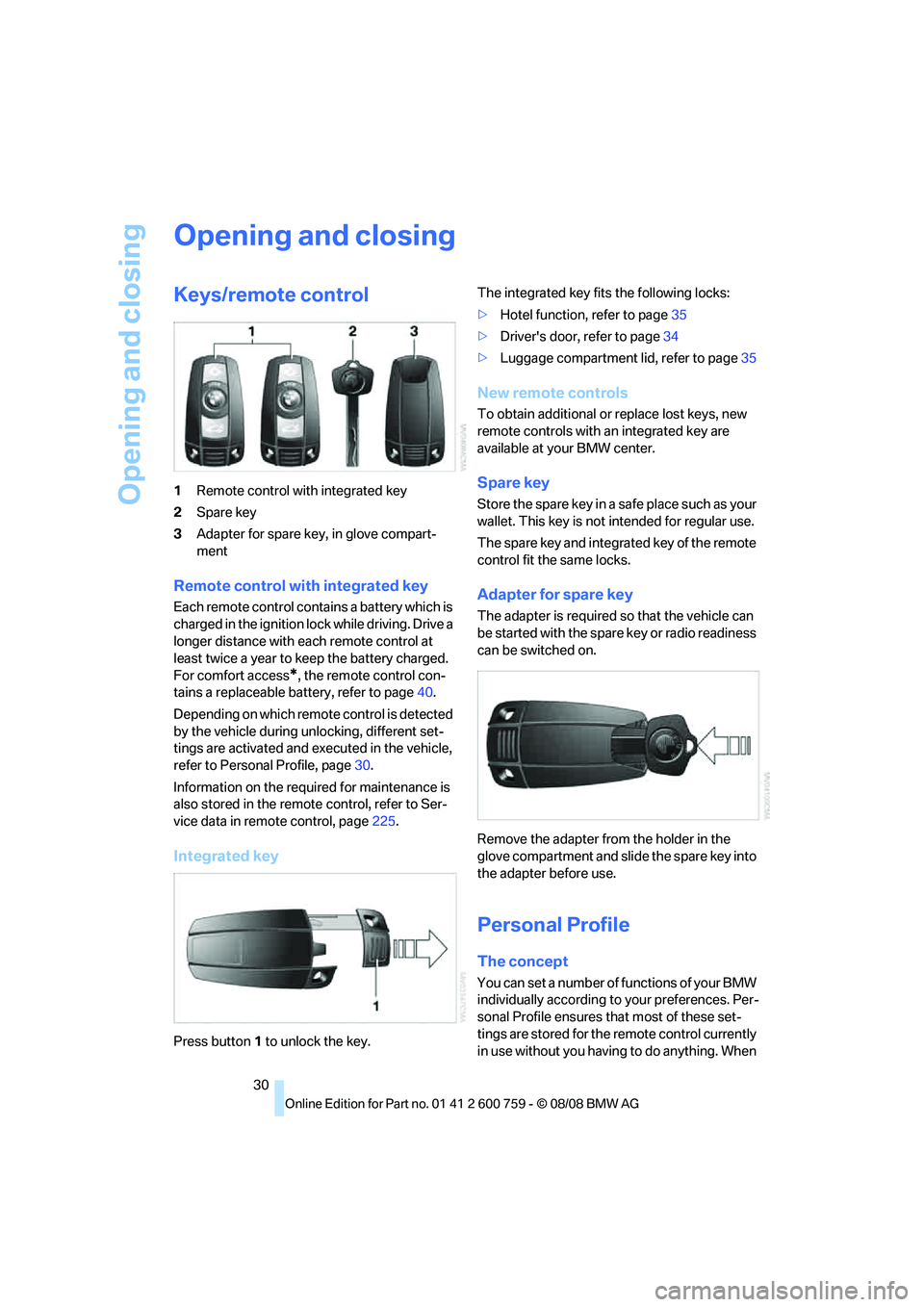
1Remote control with integrated key
2Spare key
3Adapter for spare key, in glove compart-
ment
Remote control with integrated key
Each remote control contains a battery which is
charged in the ignition lock while driving. Drive a
longer distance with each remote control at
least twice a year to keep the battery charged.
For comfort access
*, the remote control con-
tains a replaceable battery, refer to page40.
Depending on which remote control is detected
by the vehicle during unlocking, different set-
tings are activated and executed in the vehicle,
refer to Personal Profile, page30.
Information on the required for maintenance is
also stored in the remote control, refer to Ser-
vice data in remote control, page225.
Integrated key
Press button1 to unlock the key.The integrated key fits the following locks:
>Hotel function, refer to page35
>Driver's door, refer to page34
>Luggage compartment lid, refer to page35
New remote controls
To obtain additional or replace lost keys, new
remote controls with an integrated key are
available at your BMW center.
Spare key
Store the spare key in a safe place such as your
wallet. This key is not intended for regular use.
The spare key and integrated key of the remote
control fit the same locks.
Adapter for spare key
The adapter is required so that the vehicle can
be started with the spare key or radio readiness
can be switched on.
Remove the adapter from the holder in the
glove compartment and slide the spare key into
the adapter before use.
Personal Profile
The concept
You can set a number of functions of your BMW
individually according to your preferences. Per-
sonal Profile ensures that most of these set-
tings are stored for the remote control currently
in use without you having to do anything. When
Page 39 of 272
Controls
37Reference
At a glance
Driving tips
Communications
Navigation
Entertainment
Mobility
Emergency release
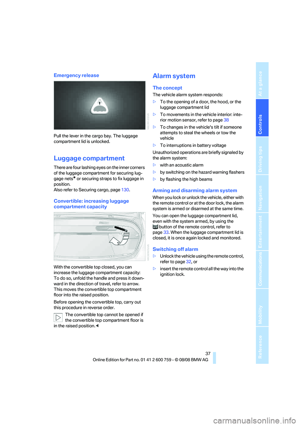
Pull the lever in the cargo bay. The luggage
compartment lid is unlocked.
Luggage compartment
There are four lashing eyes on the inner corners
of the luggage compartment for securing lug-
gage nets
* or securing straps to fix luggage in
position.
Also refer to Securing cargo, page130.
Convertible: increasing luggage
compartment capacity
With the convertible top closed, you can
increase the luggage compartment capacity:
To do so, unfold the handle and press it down-
ward in the direction of travel, refer to arrow.
This moves the convertible top compartment
floor into the raised position.
Before opening the convertible top, carry out
this procedure in reverse order.
The convertible top cannot be opened if
the convertible top compartment floor is
in the raised position.<
Alarm system
The concept
The vehicle alarm system responds:
>To the opening of a door, the hood, or the
luggage compartment lid
>To movements in the vehicle interior: inte-
rior motion sensor, refer to page38
>To changes in the vehicle's tilt if someone
attempts to steal the wheels or tow the
vehicle
>To interruptions in battery voltage
Unauthorized operations are briefly signaled by
the alarm system:
>with an acoustic alarm
>by switching on
the hazard warning flashers
>by flashing the high beams
Arming and disarming alarm system
When you lock or unlock the vehicle, either with
the remote control or at the door lock, the alarm
system is armed or disarmed at the same time.
You can open the luggage compartment lid,
even with the system armed, by using the
button of the remote control, refer to
page33. When the luggage compartment lid is
closed, it is once again locked and monitored.
Switching off alarm
>Unlock the vehicle using the remote control,
refer to page32, or
>insert the remote control all the way into the
ignition lock.
Page 46 of 272
Opening and closing
44
Sliding visor
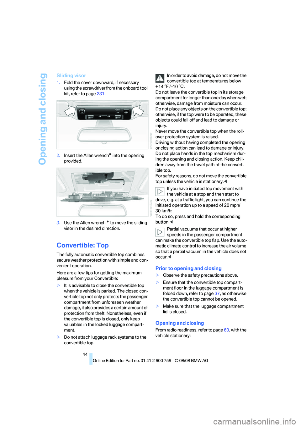
1.Fold the cover downward, if necessary
using the screwdriver from the onboard tool
kit, refer to page231.
2.Insert the Allen wrench
* into the opening
provided.
3.Use the Allen wrench
* to move the sliding
visor in the desired direction.
Convertible: Top
The fully automatic convertible top combines
secure weather protection with simple and con-
venient operation.
Here are a few tips for getting the maximum
pleasure from your Convertible:
>It is advisable to close the convertible top
when the vehicle is parked. The closed con-
vertible top not only protects the passenger
compartment from unforeseen weather
damage, it also provides a certain amount of
protection from theft. Nonetheless, even if
the convertible top is closed, only keep
valuables in the locked luggage compart-
ment.
>Do not attach luggage rack systems to the
convertible top.In order to avoid damage, do not move the
convertible top at temperatures below
+147/–106.
Do not leave the convertible top in its storage
compartment for longer than one day when wet;
otherwise, damage from moisture can occur.
Do not place any objects on the convertible top;
otherwise, if the top were to be operated, these
objects could fall off and lead to damage or
injury.
Never move the convertible top when the roll-
over protection system is raised.
Driving without having completed the opening
or closing action can lead to damage or injury.
Do not place hands in the top mechanism dur-
ing the opening and closing action. Keep chil-
dren away from the travel path of the convert-
ible top.
For safety reasons, do not move the convertible
top unless the vehicle is stationary.<
If you have initiated top movement with
the vehicle at a stop and then start to
drive, e.g. at a traffic light, you can continue the
initiated operation up to a speed of 20 mph/
30 km/h:
To do so, press and hold the corresponding
button.<
Partial vacuums that occur at higher
speeds in the passenger compartment
can make the convertible top flap. Use the auto-
matic climate control to increase the air volume
so that a partial vacuum in the vehicle does not
occur.<
Prior to opening and closing
>Observe the safety precautions above.
>Ensure that the convertible top compart-
ment floor in the luggage compartment is
folded down, refer to page37, as otherwise
the convertible top cannot be opened.
>Make sure that the luggage compartment
lid is closed.
Opening and closing
From radio readiness, refer to page60, with the
vehicle stationary:
Page 50 of 272
Opening and closing
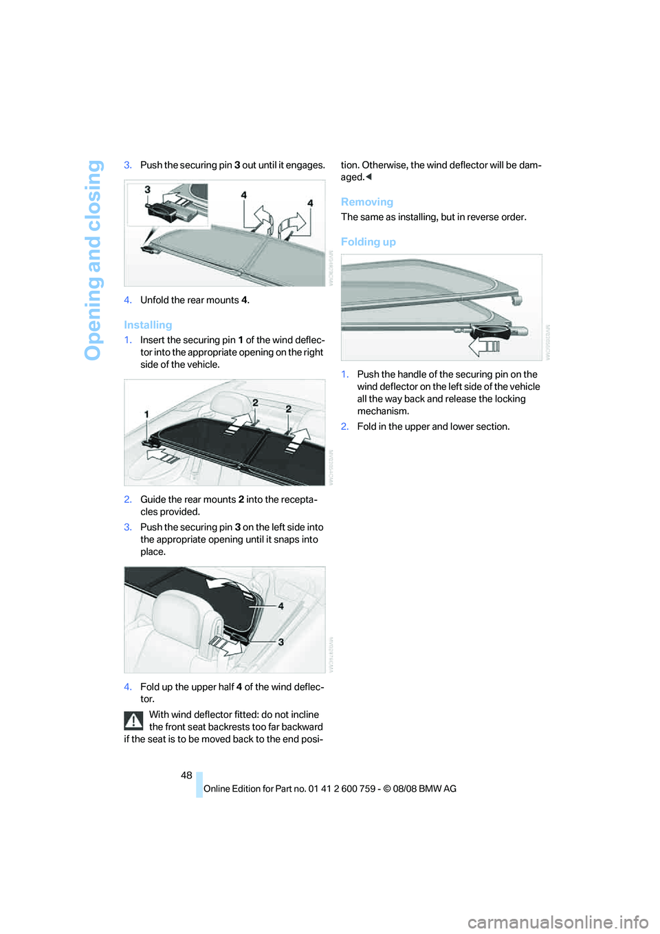
48 3.Push the securing pin3 out until it engages.
4.Unfold the rear mounts4.
Installing
1.Insert the securing pin 1 of the wind deflec-
tor into the appropriate opening on the right
side of the vehicle.
2.Guide the rear mounts2 into the recepta-
cles provided.
3.Push the securing pin3 on the left side into
the appropriate opening until it snaps into
place.
4.Fold up the upper half4 of the wind deflec-
tor.
With wind deflector fitted: do not incline
the front seat backrests too far backward
if the seat is to be moved back to the end posi-tion. Otherwise, the wind deflector will be dam-
aged.<
Removing
The same as installing, but in reverse order.
Folding up
1.Push the handle of the securing pin on the
wind deflector on the left side of the vehicle
all the way back and release the locking
mechanism.
2.Fold in the upper and lower section.
Page 60 of 272
Transporting children safely
58
Transporting children safely
The right place for children
Do not leave children unattended in the
vehicle, otherwise they could endanger
themselves and other persons, e.g. by opening
the doors.<
Children always in the rear
Accident research shows that the safest place
for children is on the rear seat.
Children younger than 13 years of age or
with a height under 5 ft/150 cm may only
be transported in the rear in child restraint sys-
tems which correspond to the age, weight and
height of the child. Otherwise there is an
increased danger of injury in an accident.<
Children 13 years of age or older must wear a
safety belt as soon as a suitable child restraint
system can no longer be used due to their age,
size and weight.
Exception for front passenger seat
Should it be necessary to use a child
restraint system on the front passenger
seat, the front, knee and side airbags on the
passenger side must be deactivated before
doing so. Otherwise, there is an increased risk
of injury to the child if the airbags are triggered,
even with a child restraint system.<
For more information on automatic deactivation
of the front passenger airbags, refer to page96.
Installing child restraint
systems
Follow child restraint system manufac-
turer's instructions for the selection,
installation and use of child restraint systems.
Otherwise, the degree of protection they offer
may be reduced.<
On front passenger seat
After mounting a child restraint system on
the front passenger seat, make sure that
the front and side airbags on the front passen-
ger side are deactivated, as otherwise there is
an increased risk of injury if the airbags are trig-
gered.<
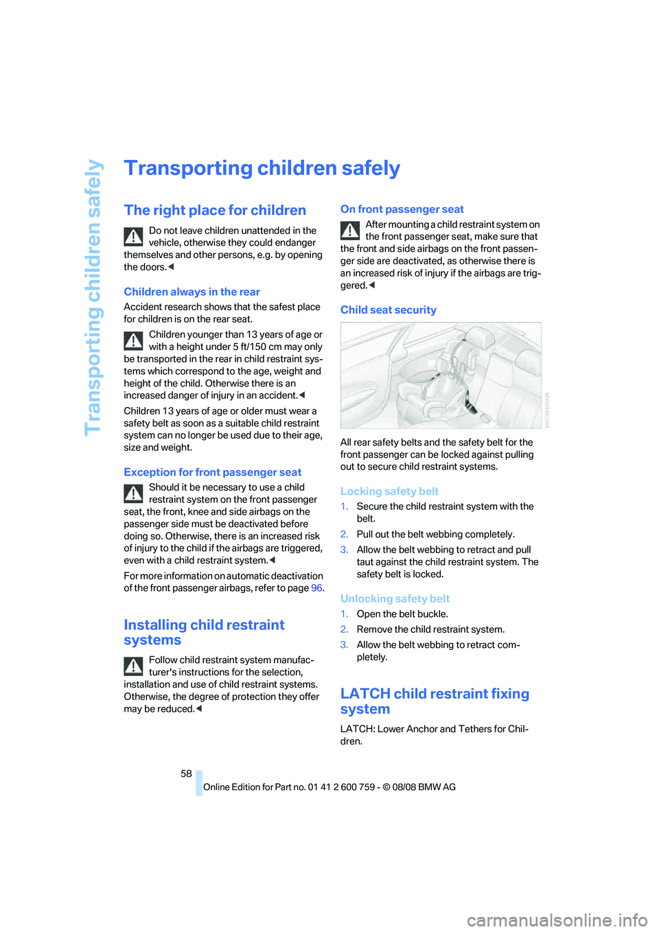
Child seat security
All rear safety belts and the safety belt for the
front passenger can be locked against pulling
out to secure child restraint systems.
Locking safety belt
1.Secure the child restraint system with the
belt.
2.Pull out the belt webbing completely.
3.Allow the belt webbing to retract and pull
taut against the child restraint system. The
safety belt is locked.
Unlocking safety belt
1.Open the belt buckle.
2.Remove the child restraint system.
3.Allow the belt webbing to retract com-
pletely.
LATCH child restraint fixing
system
LATCH: Lower Anchor and Tethers for Chil-
dren.
Page 61 of 272
Controls
59Reference
At a glance
Driving tips
Communications
Navigation
Entertainment
Mobility
Follow the system manufacturer's
instructions on installation and use of
LATCH child restraint systems in order not to
impair their protective function.<
Anchor points for LATCH mounts
Before attaching the LATCH child's seat, pull
the belt away from the region of the child
restraint fixing system.
Make sure that both of the lower LATCH
mounts have properly clicked into place
and that the child restraint system is resting
snugly against the backrest. Otherwise, the
protective action may be impeded.<
Rear seats
The mounting points for the LATCH anchors
are located at the positions indicated by arrows
in the gap between the seat and the backrest.
Coupe: child restraint system with
tether strap
Only use the top tether-strap mounting
points to secure child restraint systems,
otherwise the mounting points could be dam-
aged.
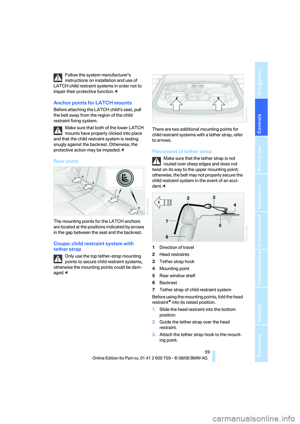
to arrows.
Placement of tether strap
Make sure that the tether strap is not
routed over sharp edges and does not
twist on its way to the upper mounting point;
otherwise, the belt may not properly secure the
child restraint system in the event of an acci-
dent.<
1Direction of travel
2Head restraints
3Tether strap hook
4Mounting point
5Rear window shelf
6Backrest
7Tether strap of child restraint system
Before using the mounting points, fold the head
restraint
* into its raised position.
1.Slide the head restraint into the bottom
position.
2.Guide the tether strap over the head
restraint.
3.Attach the tether strap hook to the mount-
ing point.
Page 65 of 272
Controls
63Reference
At a glance
Driving tips
Communications
Navigation
Entertainment
Mobility
The transmission mode and the currently
selected gear are displayed.
Engaging transmission position
>Do not leave the transmission position P
until the engine is running: interlock.
>With the vehicle stationary, depress the
brake pedal before shifting out of P or N;
otherwise the shift command will not be
executed: shiftlock.
To prevent the vehicle from creeping
after you select a driving position,
maintain pressure on the brake pedal until
you are ready to start.<
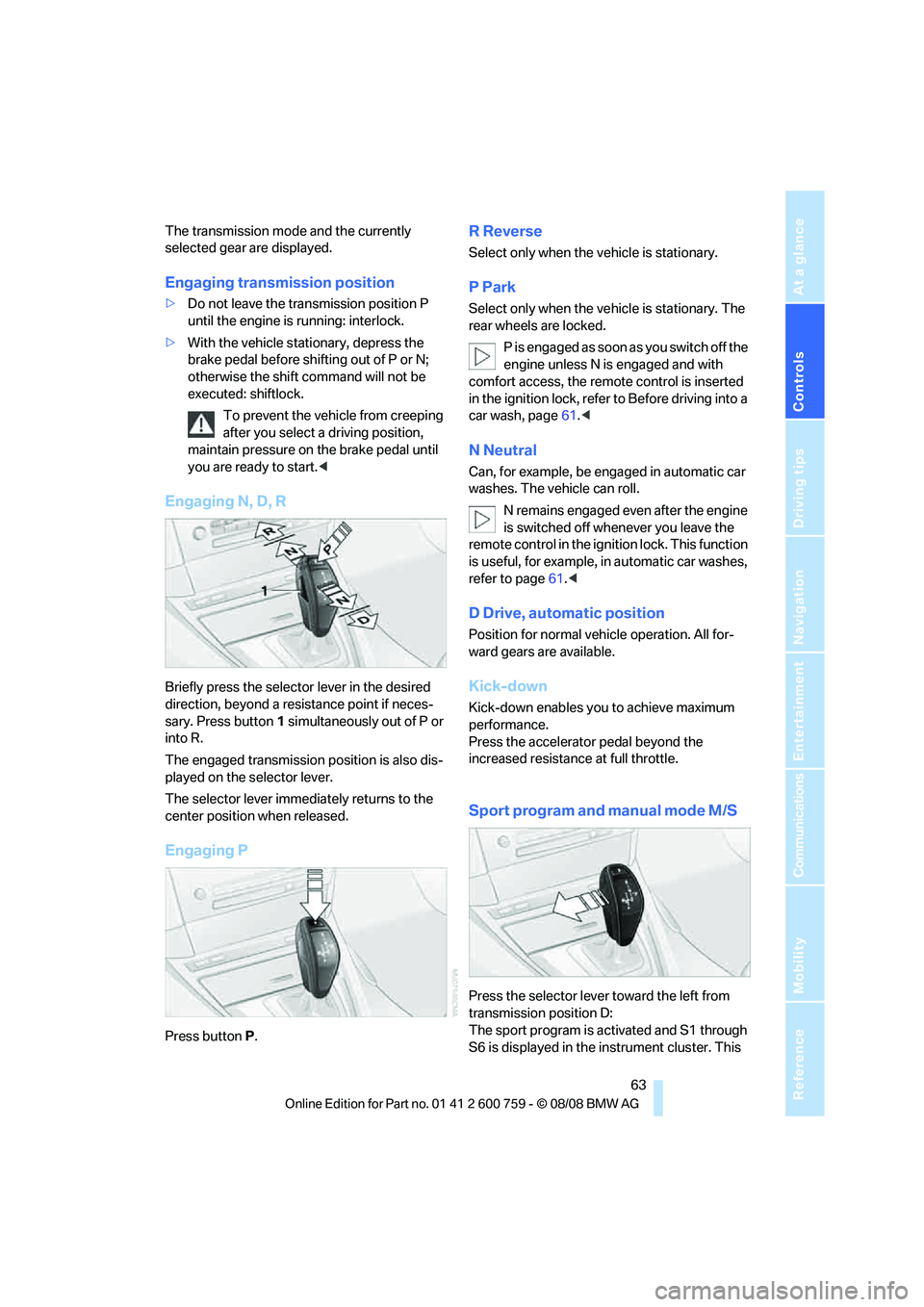
Engaging N, D, R
Briefly press the selector lever in the desired
direction, beyond a resistance point if neces-
sary. Press button1 simultaneously out of P or
into R.
The engaged transmission position is also dis-
played on the selector lever.
The selector lever immediately returns to the
center position when released.
Engaging P
Press buttonP.
R Reverse
Select only when the vehicle is stationary.
P Park
Select only when the vehicle is stationary. The
rear wheels are locked.
P is engaged as soon as you switch off the
engine unless N is engaged and with
comfort access, the remote control is inserted
in the ignition lock, refer to Before driving into a
car wash, page61.<
N Neutral
Can, for example, be engaged in automatic car
washes. The vehicle can roll.
N remains engaged even after the engine
is switched off whenever you leave the
remote control in the ignition lock. This function
is useful, for example, in automatic car washes,
refer to page61.<
D Drive, automatic position
Position for normal vehicle operation. All for-
ward gears are available.
Kick-down
Kick-down enables you to achieve maximum
performance.
Press the accelerator pedal beyond the
increased resistance at full throttle.
Sport program and manual mode M/S
Press the selector lever toward the left from
transmission position D:
The sport program is activated and S1 through
S6 is displayed in the instrument cluster. This
Page 85 of 272
Controls
83Reference
At a glance
Driving tips
Communications
Navigation
Entertainment
Mobility
Displaying the urgency of malfunctions
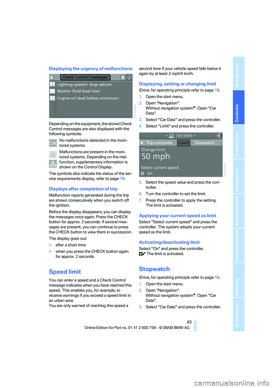
Depending on the equipment, the stored Check
Control messages are also displayed with the
following symbols:
No malfunctions detected in the moni-
tored systems.
Malfunctions are present in the moni-
tored systems. Depending on the mal-
function, supplementary information is
shown on the Control Display.
The symbols also indicate the status of the ser-
vice requirements display, refer to page79.
Displays after completion of trip
Malfunction reports generated during the trip
are shown consecutively when you switch off
the ignition.
Before the display disappears, you can display
the messages once again. Press the CHECK
button for approx. 2 seconds. If several mes-
sages are present, you can continue to press
the CHECK button to view them in succession.
The display goes out:
>after a short time
>when you press the CHECK button again
for approx. 2 seconds
Speed limit
You can enter a speed and a Check Control
message indicates when you have reached this
speed. This enables you, for example, to
receive warnings if you exceed a speed limit in
an urban area.
You are only warned of reaching this speed a second time if your vehicle speed falls below it
again by at least 3 mph/5 km/h.
Displaying, setting or changing limit
iDrive, for operating principle refer to page16.
1.Open the start menu.
2.Open "Navigation".
Without navigation system
*: Open "Car
Data".
3.Select "Car Data" and press the controller.
4.Select "Limit" and press the controller.
5.Select the speed value and press the con-
troller.
6.Turn the controller to set the limit.
7.Press the controller to apply the setting.
The limit is activated.
Applying your current speed as limit
Select "Select current speed" and press the
controller. The system adopts your current
speed as the limit.
Activating/deactivating limit
Select "On" and press the controller.
The limit is activated.
Stopwatch
iDrive, for operating principle refer to page16.
1.Open the start menu.
2.Open "Navigation".
Without navigation system
*: Open "Car
Data".
3.Select "Car Data" and press the controller.
Page 91 of 272
Controls
89Reference
At a glance
Driving tips
Communications
Navigation
Entertainment
Mobility
Do not reduce the pressure on the brake pedal
for the duration of the full braking.
Adaptive brake assistant*
In conjunction with the active cruise control
with the stop-and-go function, the adaptive
brake assistant ensures that the brake
responds even more quickly during braking
with the brake assistant.
DSC Dynamic Stability Control
DSC prevents traction loss in the driving wheels
when starting off and accelerating. The system
also identifies unstable driving conditions, such
as a loss of traction at the rear of the vehicle or
sliding of the vehicle in its front wheels. In these
cases, DSC helps the vehicle maintain a safe
course within physical limits by reducing engine
output and through braking actions in the indi-
vidual wheels.
The laws of physics cannot be repealed,
even with DSC. An appropriate driving
style always remains the responsibility of the
driver. Therefore, do not restrict the additional
safety margin with a risky driving style, as other-
wise there is a risk of an accident.<
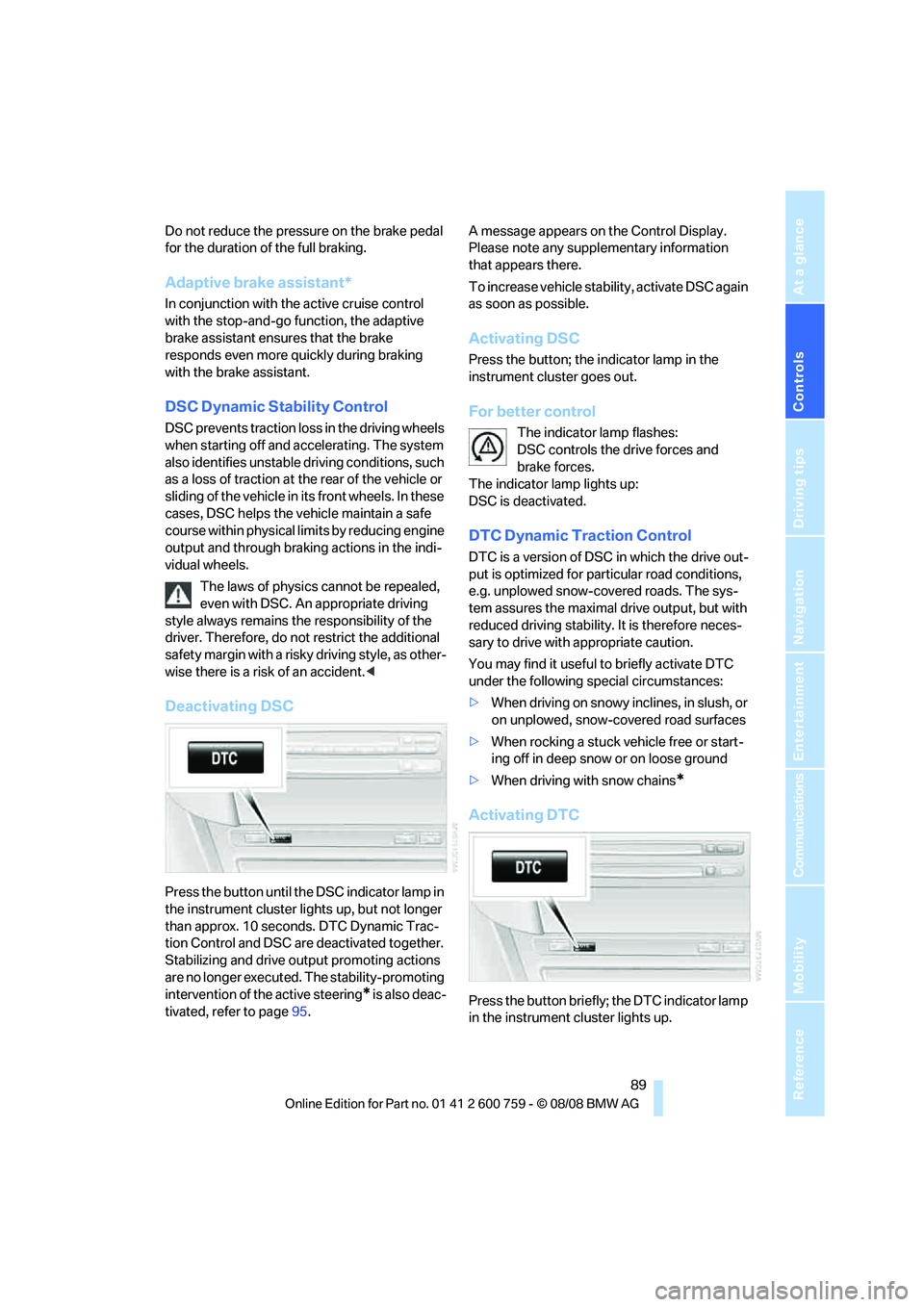
Deactivating DSC
Press the button until the DSC indicator lamp in
the instrument cluster lights up, but not longer
than approx. 10 seconds. DTC Dynamic Trac-
tion Control and DSC are deactivated together.
Stabilizing and drive output promoting actions
are no longer executed. The stability-promoting
intervention of the active steering
* is also deac-
tivated, refer to page95.A message appears on the Control Display.
Please note any supplementary information
that appears there.
To increase vehicle stability, activate DSC again
as soon as possible.
Activating DSC
Press the button; the indicator lamp in the
instrument cluster goes out.
For better control
The indicator lamp flashes:
DSC controls the drive forces and
brake forces.
The indicator lamp lights up:
DSC is deactivated.
DTC Dynamic Traction Control
DTC is a version of DSC in which the drive out-
put is optimized for particular road conditions,
e.g. unplowed snow-covered roads. The sys-
tem assures the maximal drive output, but with
reduced driving stability. It is therefore neces-
sary to drive with appropriate caution.
You may find it useful to briefly activate DTC
under the following special circumstances:
>When driving on snowy inclines, in slush, or
on unplowed, snow-covered road surfaces
>When rocking a stuck vehicle free or start-
ing off in deep snow or on loose ground
>When driving with snow chains
*
Activating DTC
Press the button briefly; the DTC indicator lamp
in the instrument cluster lights up.