fuel BMW 6 SERIES COUPE 2014 F13 User Guide
[x] Cancel search | Manufacturer: BMW, Model Year: 2014, Model line: 6 SERIES COUPE, Model: BMW 6 SERIES COUPE 2014 F13Pages: 247, PDF Size: 5.08 MB
Page 89 of 247
Therefore, drive carefully on bridges and
shaded roads, e.g., to avoid the increased risk
of an accident.◀
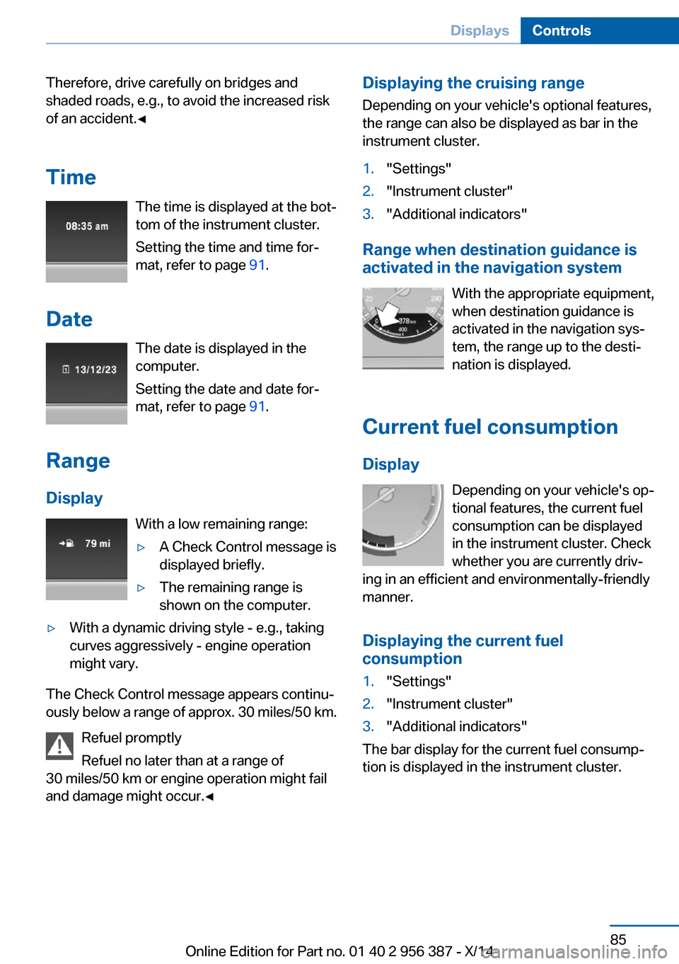
Time The time is displayed at the bot‐
tom of the instrument cluster.
Setting the time and time for‐
mat, refer to page 91.
Date The date is displayed in the
computer.
Setting the date and date for‐
mat, refer to page 91.
Range
Display With a low remaining range:▷A Check Control message is
displayed briefly.▷The remaining range is
shown on the computer.▷With a dynamic driving style - e.g., taking
curves aggressively - engine operation
might vary.
The Check Control message appears continu‐
ously below a range of approx. 30 miles/50 km.
Refuel promptly
Refuel no later than at a range of
30 miles/50 km or engine operation might fail
and damage might occur.◀
Displaying the cruising range
Depending on your vehicle's optional features,
the range can also be displayed as bar in the
instrument cluster.1."Settings"2."Instrument cluster"3."Additional indicators"
Range when destination guidance is
activated in the navigation system
With the appropriate equipment,
when destination guidance is
activated in the navigation sys‐
tem, the range up to the desti‐
nation is displayed.
Current fuel consumption
Display Depending on your vehicle's op‐
tional features, the current fuel
consumption can be displayed
in the instrument cluster. Check
whether you are currently driv‐
ing in an efficient and environmentally-friendly
manner.
Displaying the current fuel
consumption
1."Settings"2."Instrument cluster"3."Additional indicators"
The bar display for the current fuel consump‐
tion is displayed in the instrument cluster.
Seite 85DisplaysControls85
Online Edition for Part no. 01 40 2 956 387 - X/14
Page 90 of 247
Energy recoveryDisplay The kinetic energy of the vehicle
is converted to electrical energy while coasting. The vehicle bat‐
tery is partially charged and fuel
consumption can be reduced.
Service requirements The concept
After the ignition is turned on the instrument
cluster briefly displays available driving dis‐
tance or time to the next scheduled mainte‐
nance.
Your service specialist can read the current
service requirements from your remote con‐
trol.
Display
Data regarding the service status or legally
mandated vehicle inspections are automati‐
cally transmitted to your service center before
a service due date.
Detailed information on service
requirements
More information on the scope of service re‐
quired can be displayed on the Control Dis‐
play.
On the Control Display:1."Vehicle info"2."Vehicle status"3. "Service required"
Required maintenance procedures and le‐
gally mandated inspections are displayed.4.Select an entry to call up detailed informa‐
tion.SymbolsSym‐
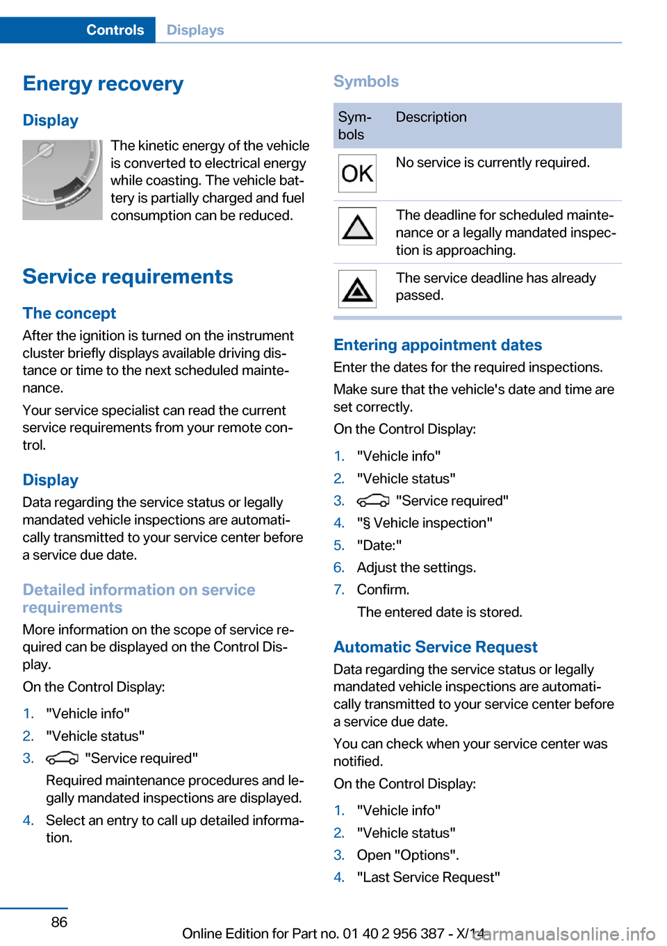
bolsDescriptionNo service is currently required.The deadline for scheduled mainte‐
nance or a legally mandated inspec‐
tion is approaching.The service deadline has already
passed.
Entering appointment dates
Enter the dates for the required inspections.
Make sure that the vehicle's date and time are
set correctly.
On the Control Display:
1."Vehicle info"2."Vehicle status"3. "Service required"4."§ Vehicle inspection"5."Date:"6.Adjust the settings.7.Confirm.
The entered date is stored.
Automatic Service Request
Data regarding the service status or legally
mandated vehicle inspections are automati‐
cally transmitted to your service center before
a service due date.
You can check when your service center was
notified.
On the Control Display:
1."Vehicle info"2."Vehicle status"3.Open "Options".4."Last Service Request"Seite 86ControlsDisplays86
Online Edition for Part no. 01 40 2 956 387 - X/14
Page 91 of 247
Gear shift indicatorThe conceptThe system recommends the most fuel effi‐
cient gear for the current driving situation.
Depending on the vehicle's features and coun‐
try version of the vehicle, the gear shift indica‐
tor is active in the manual mode of the Step‐
tronic transmission and with manual
transmission.
Suggestions to shift gear up or down are dis‐
played in the instrument cluster.
On vehicles without a gear shift indicator, the
engaged gear is displayed.
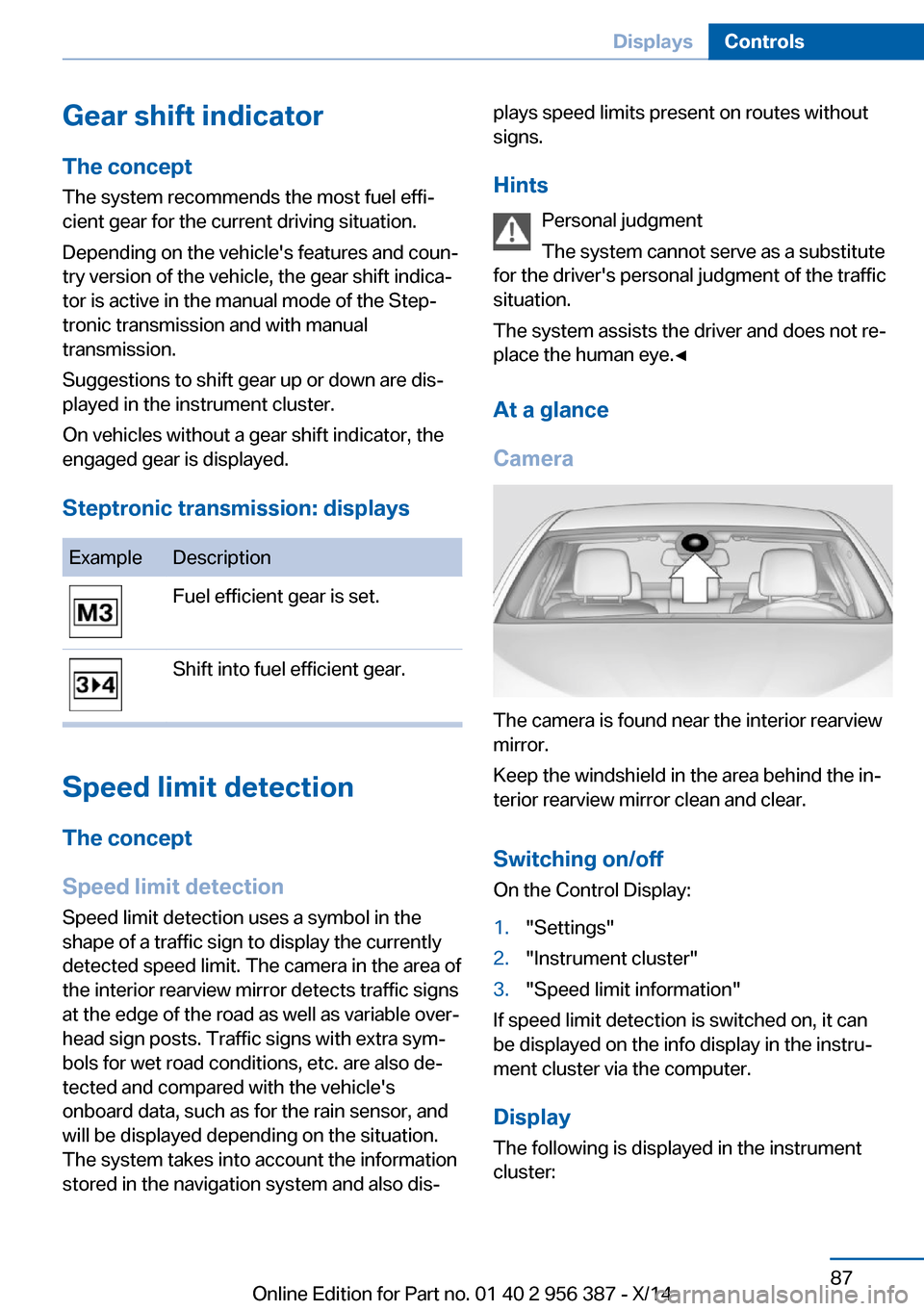
Steptronic transmission: displaysExampleDescriptionFuel efficient gear is set.Shift into fuel efficient gear.
Speed limit detection
The concept
Speed limit detection
Speed limit detection uses a symbol in the
shape of a traffic sign to display the currently
detected speed limit. The camera in the area of
the interior rearview mirror detects traffic signs
at the edge of the road as well as variable over‐
head sign posts. Traffic signs with extra sym‐
bols for wet road conditions, etc. are also de‐
tected and compared with the vehicle's
onboard data, such as for the rain sensor, and
will be displayed depending on the situation.
The system takes into account the information
stored in the navigation system and also dis‐
plays speed limits present on routes without
signs.
Hints Personal judgment
The system cannot serve as a substitute
for the driver's personal judgment of the traffic
situation.
The system assists the driver and does not re‐
place the human eye.◀
At a glance
Camera
The camera is found near the interior rearview
mirror.
Keep the windshield in the area behind the in‐
terior rearview mirror clean and clear.
Switching on/offOn the Control Display:
1."Settings"2."Instrument cluster"3."Speed limit information"
If speed limit detection is switched on, it can
be displayed on the info display in the instru‐
ment cluster via the computer.
Display The following is displayed in the instrument
cluster:
Seite 87DisplaysControls87
Online Edition for Part no. 01 40 2 956 387 - X/14
Page 93 of 247
Using the thumbwheel, select the desired set‐
ting and confirm it by pushing the thumbwheel.
Computer
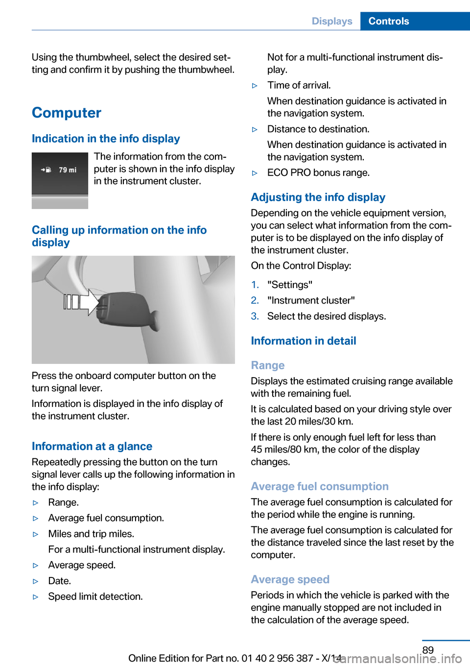
Indication in the info display The information from the com‐
puter is shown in the info display
in the instrument cluster.
Calling up information on the info display
Press the onboard computer button on the
turn signal lever.
Information is displayed in the info display of
the instrument cluster.
Information at a glance
Repeatedly pressing the button on the turn
signal lever calls up the following information in
the info display:
▷Range.▷Average fuel consumption.▷Miles and trip miles.
For a multi-functional instrument display.▷Average speed.▷Date.▷Speed limit detection.Not for a multi-functional instrument dis‐
play.▷Time of arrival.
When destination guidance is activated in
the navigation system.▷Distance to destination.
When destination guidance is activated in
the navigation system.▷ECO PRO bonus range.
Adjusting the info display
Depending on the vehicle equipment version,
you can select what information from the com‐
puter is to be displayed on the info display of
the instrument cluster.
On the Control Display:
1."Settings"2."Instrument cluster"3.Select the desired displays.
Information in detail
Range
Displays the estimated cruising range available
with the remaining fuel.
It is calculated based on your driving style over
the last 20 miles/30 km.
If there is only enough fuel left for less than
45 miles/80 km, the color of the display
changes.
Average fuel consumption
The average fuel consumption is calculated for
the period while the engine is running.
The average fuel consumption is calculated for
the distance traveled since the last reset by the
computer.
Average speed
Periods in which the vehicle is parked with the
engine manually stopped are not included in
the calculation of the average speed.
Seite 89DisplaysControls89
Online Edition for Part no. 01 40 2 956 387 - X/14
Page 94 of 247
Resetting average values
Press and hold the onboard computer button
on the turn signal lever.
Distance to destination
The distance remaining to the destination is
displayed if a destination is entered in the navi‐
gation system before the trip is started.
The distance to the destination is adopted au‐
tomatically.
Time of arrival The estimated time of arrival is
displayed if a destination is en‐
tered in the navigation system
before the trip is started.
The time must be correctly set.
Speed limit detection Description of the speed limit detection, refer
to page 87, function.
Trip computer The vehicle features two types of board com‐
puters.▷"Onboard info": the values can be reset as
often as necessary.▷"Trip computer": the values provide an
overview of the current trip.
Resetting the trip computer
On the Control Display:
1."Vehicle info"2."Trip computer"3."Reset": all values are reset.
"Automatically reset": all values are reset
approx. 4 hours after the vehicle came to a
standstill.Display on the Control Display
Display the computer or trip computer on the
Control Display.1."Vehicle info"2."Onboard info" or "Trip computer"
Resetting the fuel consumption or
speed
On the Control Display:
1."Vehicle info"2."Onboard info"3."Consumpt." or "Speed"4."Yes"
Sport displays
The concept
On the Control Display, the current values for
performance and torque can be displayed if
the vehicle is appropriately equipped.
Displaying sport displays on the
Control Display
1."Vehicle info"2."Sport displays"
Speed warning
The concept Displays a speed, when reached, should cause
a warning to be issued.
The warning is repeated if the vehicle speed
drops below the set speed once by at least
3 mph/5 km/h.
Seite 90ControlsDisplays90
Online Edition for Part no. 01 40 2 956 387 - X/14
Page 96 of 247
5.Press the controller.6.Make the necessary settings for the month
and year.
The date is stored.
Setting the date format
1."Settings"2."Time/Date"3."Format:"4.Select the desired format.
The date format is stored.
Language
Setting the language
To set the language on the Control Display:
1."Settings"2."Language/Units"3."Language:"4.Select the desired language.
Settings are stored for the profile currently in
use.
Setting the voice dialog
Voice dialog for the voice activation system,
refer to page 27.
Units of measure
Setting the units of measure
To set the units for fuel consumption, route/
distance and temperature:
1."Settings"2."Language/Units"3.Select the desired menu item.4.Select the desired unit.
Settings are stored for the profile currently in
use.
Brightness
Setting the brightness
To set the brightness of the Control Display:1."Settings"2."Control display"3."Brightness"4.Turn the controller until the desired bright‐
ness is set.5.Press the controller.
Settings are stored for the profile currently in
use.
Depending on the light conditions, the bright‐
ness settings may not be clearly visible.
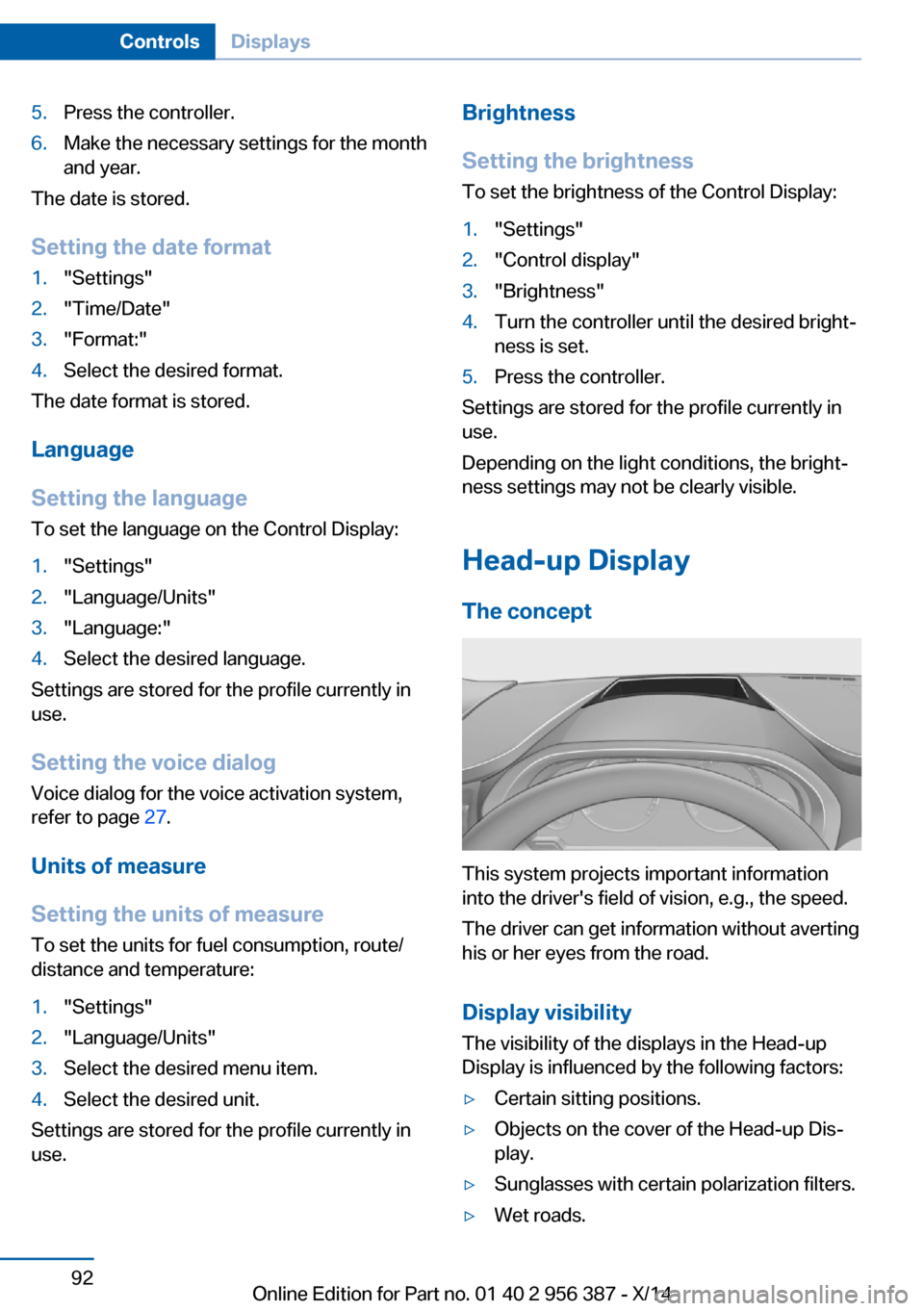
Head-up Display
The concept
This system projects important information
into the driver's field of vision, e.g., the speed.
The driver can get information without averting
his or her eyes from the road.
Display visibility The visibility of the displays in the Head-up
Display is influenced by the following factors:
▷Certain sitting positions.▷Objects on the cover of the Head-up Dis‐
play.▷Sunglasses with certain polarization filters.▷Wet roads.Seite 92ControlsDisplays92
Online Edition for Part no. 01 40 2 956 387 - X/14
Page 110 of 247
System limits
The system does not function properly if a re‐
set has not been carried out, e.g., a flat tire is
reported though tire inflation pressures are
correct.
The tire inflation pressure depends on the
tire's temperature. Driving or exposure to the
sun will increase the tire's temperature, thus
increasing the tire inflation pressure. The tire
inflation pressure is reduced when the tire
temperature falls again. These circumstances
may cause a warning when temperatures fall
very sharply.
Malfunction The yellow warning lamp flashes and
then lights up continuously. A Check
Control message is displayed. No flat
tire or loss of tire inflation pressure can be de‐
tected.
Display in the following situations:▷A wheel without TPM electronics is fitted:
have the service center check it if needed.▷Malfunction: have the system checked by
your service center.▷TPM was unable to complete the reset.
Reset the system again.▷Interference through systems or devices
with the same radio frequency: after leav‐
ing the area of the interference, the system
automatically becomes active again.
Declaration according to NHTSA/
FMVSS 138 Tire Pressure Monitoring
System
Each tire, including the spare (if provided)
should be checked monthly when cold and in‐
flated to the inflation pressure recommended
by the vehicle manufacturer on the vehicle
placard or tire inflation pressure label. (If your
vehicle has tires of a different size than the size
indicated on the vehicle placard or tire inflation
pressure label, you should determine the
proper tire inflation pressure for those tires.)
As an added safety feature, your vehicle has
been equipped with a tire pressure monitoring
system (TPMS) that illuminates a low tire pres‐
sure telltale when one or more of your tires is
significantly under-inflated. Accordingly, when
the low tire pressure telltale illuminates, you
should stop and check your tires as soon as
possible, and inflate them to the proper pres‐
sure. Driving on a significantly under-inflated
tire causes the tire to overheat and can lead to
tire failure. Under-inflation also reduces fuel ef‐
ficiency and tire tread life, and may affect the
vehicle's handling and stopping ability. Please
note that the TPMS is not a substitute for
proper tire maintenance, and it is the driver's
responsibility to maintain correct tire pressure,
even if under-inflation has not reached the
level to trigger illumination of the TPMS low
tire pressure telltale. Your vehicle has also
been equipped with a TPMS malfunction indi‐
cator to indicate when the system is not oper‐
ating properly. The TPMS malfunction indica‐
tor is combined with the low tire pressure
telltale. When the system detects a malfunc‐
tion, the telltale will flash for approximately one
minute and then remain continuously illumi‐
nated. This sequence will continue upon sub‐
sequent vehicle start-ups as long as the mal‐
function exists. When the malfunction indicator
is illuminated, the system may not be able to
detect or signal low tire pressure as intended.
TPMS malfunctions may occur for a variety of
reasons, including the installation of replace‐
ment or alternate tires or wheels on the vehicle
that prevent the TPMS from functioning prop‐
erly. Always check the TPMS malfunction tell‐
tale after replacing one or more tires or wheels
on your vehicle to ensure that the replacement
or alternate tires and wheels allow the TPMS
to continue to function properly.Seite 106ControlsSafety106
Online Edition for Part no. 01 40 2 956 387 - X/14
Page 138 of 247
ECO PROECO PRO, refer to page 178, provides consis‐
tent tuning to minimize fuel consumption for
maximum range with maximum driving stabili‐
zation.
Comfort functions and the engine controller
are adjusted.
The program can be configured to individual
specifications.
Activating ECO PRO Press button repeatedly until ECO
PRO is displayed in the instrument
cluster.
Configuring ECO PRO1.Activate ECO PRO.2."Configure ECO PRO"
Make the desired settings.
Configure driving mode
Settings can be made for the following driving
modes in Driving mode:
▷SPORT mode, refer to page 133.▷ECO PRO mode, refer to page 179.
Displays in the instrument cluster
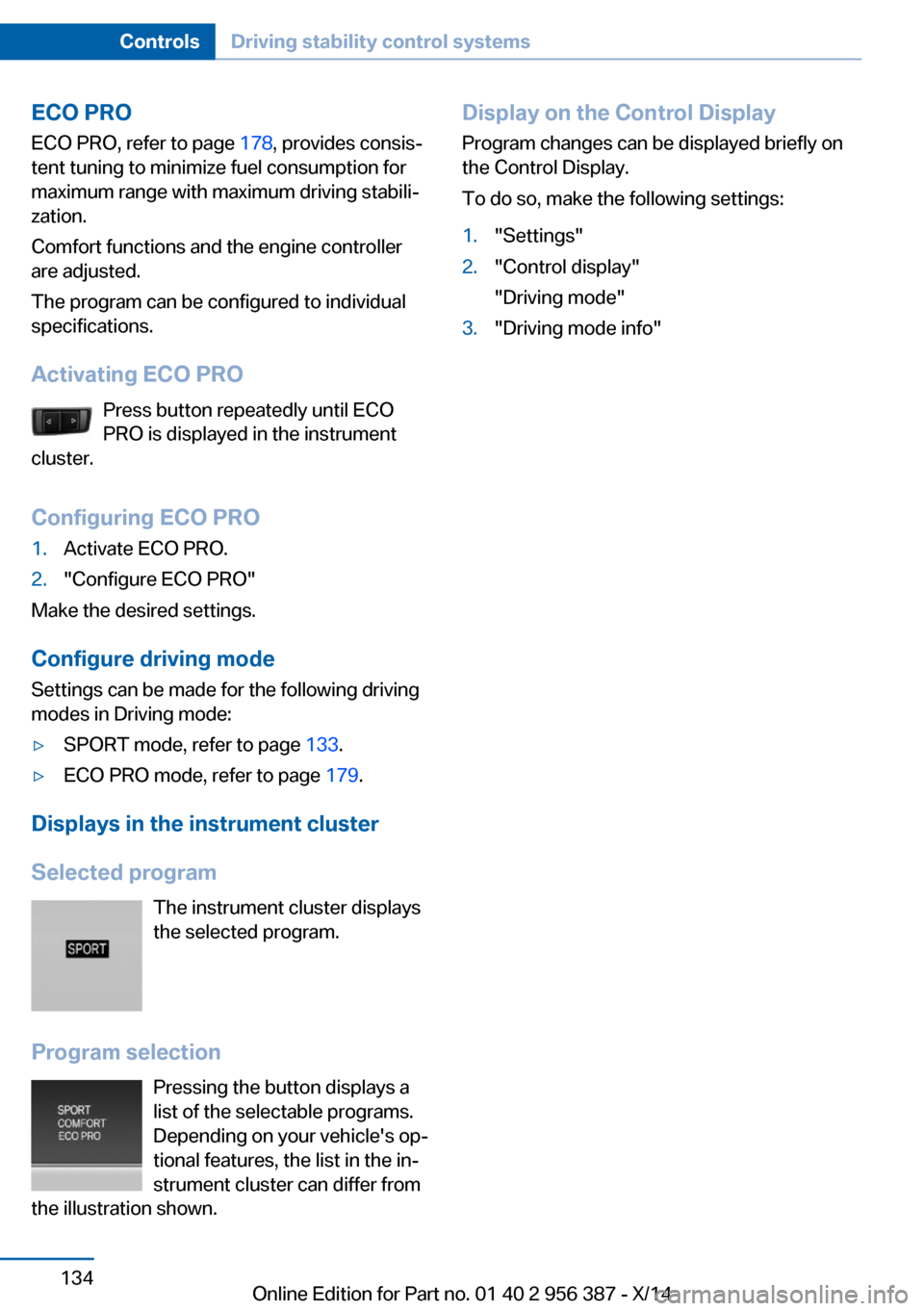
Selected program The instrument cluster displays
the selected program.
Program selection Pressing the button displays a
list of the selectable programs.
Depending on your vehicle's op‐
tional features, the list in the in‐
strument cluster can differ from
the illustration shown.
Display on the Control Display
Program changes can be displayed briefly on
the Control Display.
To do so, make the following settings:1."Settings"2."Control display"
"Driving mode"3."Driving mode info"Seite 134ControlsDriving stability control systems134
Online Edition for Part no. 01 40 2 956 387 - X/14
Page 163 of 247
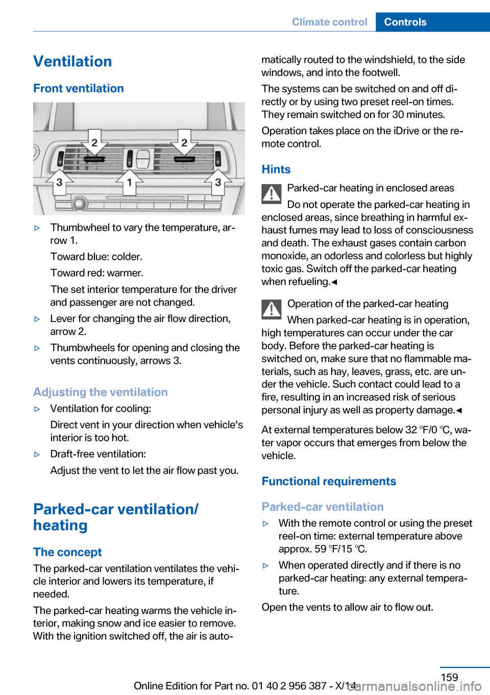
VentilationFront ventilation▷Thumbwheel to vary the temperature, ar‐
row 1.
Toward blue: colder.
Toward red: warmer.
The set interior temperature for the driver
and passenger are not changed.▷Lever for changing the air flow direction,
arrow 2.▷Thumbwheels for opening and closing the
vents continuously, arrows 3.
Adjusting the ventilation
▷Ventilation for cooling:
Direct vent in your direction when vehicle's
interior is too hot.▷Draft-free ventilation:
Adjust the vent to let the air flow past you.
Parked-car ventilation/
heating
The concept The parked-car ventilation ventilates the vehi‐
cle interior and lowers its temperature, if
needed.
The parked-car heating warms the vehicle in‐
terior, making snow and ice easier to remove.
With the ignition switched off, the air is auto‐
matically routed to the windshield, to the side
windows, and into the footwell.
The systems can be switched on and off di‐
rectly or by using two preset reel-on times.
They remain switched on for 30 minutes.
Operation takes place on the iDrive or the re‐ mote control.
Hints Parked-car heating in enclosed areas
Do not operate the parked-car heating in
enclosed areas, since breathing in harmful ex‐
haust fumes may lead to loss of consciousness
and death. The exhaust gases contain carbon
monoxide, an odorless and colorless but highly
toxic gas. Switch off the parked-car heating
when refueling.◀
Operation of the parked-car heating
When parked-car heating is in operation,
high temperatures can occur under the car
body. Before the parked-car heating is switched on, make sure that no flammable ma‐
terials, such as hay, leaves, grass, etc. are un‐
der the vehicle. Such contact could lead to a
fire, resulting in an increased risk of serious
personal injury as well as property damage.◀
At external temperatures below 32 ℉/0 ℃, wa‐
ter vapor occurs that emerges from below the
vehicle.
Functional requirements
Parked-car ventilation▷With the remote control or using the preset
reel-on time: external temperature above
approx. 59 ℉/15 ℃.▷When operated directly and if there is no
parked-car heating: any external tempera‐
ture.
Open the vents to allow air to flow out.
Seite 159Climate controlControls159
Online Edition for Part no. 01 40 2 956 387 - X/14
Page 164 of 247
Parked-car heating▷With the remote control or using the preset
reel-on time: external temperature below
approx. 59 ℉/15 ℃.▷Direct operation: any external temperature.▷The battery is sufficiently charged.▷The fuel tank is filled to above the reserve
range.
If the parked-car heating has not been used for
several months, it may be necessary to reel the
system on again after several minutes.
Switching on/off directly
On the Control Display:
1."Settings"2."Climate"3."Activate comfort heating" or
"Activate comf. ventilation"
The symbol on the automatic climate con‐
trol flashes if the system is switched on.
The system continues to run for some time af‐
ter being switched off.
Preselecting the reel-on time On the Control Display:
1."Settings"2."Climate"3."Timer 1:" or "Timer 2:"4.Set the desired time.
Activating the reel-on time
On the Control Display:
1."Settings"2."Climate"3."Activate timer 1" or "Activate timer 2"
The symbol on the automatic climate con‐
trol lights up when the reel-on time is acti‐
vated.
The symbol on the automatic climate con‐
trol flashes when the system has been
switched on.
The system will only be switched on within the
next 24 hours. After that, it needs to be reacti‐
vated.
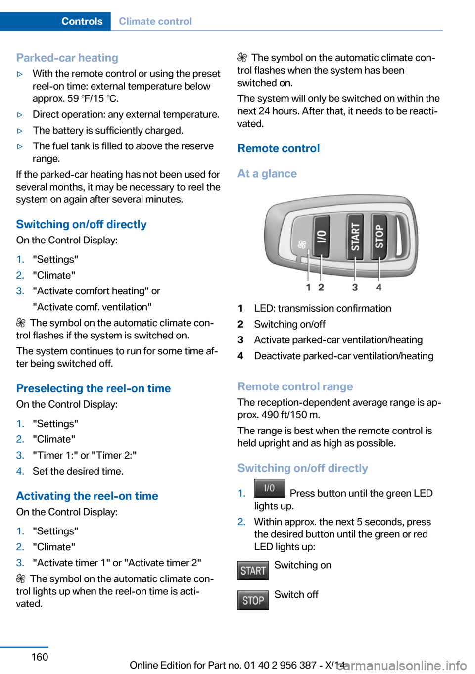
Remote control
At a glance1LED: transmission confirmation2Switching on/off3Activate parked-car ventilation/heating4Deactivate parked-car ventilation/heating
Remote control range The reception-dependent average range is ap‐
prox. 490 ft/150 m.
The range is best when the remote control is
held upright and as high as possible.
Switching on/off directly
1. Press button until the green LED
lights up.2.Within approx. the next 5 seconds, press
the desired button until the green or red
LED lights up:
Switching on
Switch off
Seite 160ControlsClimate control160
Online Edition for Part no. 01 40 2 956 387 - X/14