service indicator BMW 6 SERIES GRAN COUPE 2017 Owners Manual
[x] Cancel search | Manufacturer: BMW, Model Year: 2017, Model line: 6 SERIES GRAN COUPE, Model: BMW 6 SERIES GRAN COUPE 2017Pages: 261, PDF Size: 5.24 MB
Page 56 of 261
Unbuckling the safety belt1.Hold the safety belt firmly.2.Press the red button in the belt buckle.3.Guide the safety belt back into its roll-up
mechanism.
Safety belt reminder for driver's and
passenger's seat
The indicator lamp lights up and a sig‐
nal sounds. Make sure that the safety
belts are positioned correctly. The
safety belt reminder is active at speeds above
approx. 6 mph/10 km/h. It can also be activated
if objects are placed on the front passenger
seat.
Safety mode In critical situations, for example during an
emergency stop, the front safety belts tighten
automatically.
If the situation passes without an accident oc‐
curring, the belt tension relaxes.
If the belt tension does not loosen automati‐
cally, stop the vehicle and unbuckle the safety
belt using the red button in the buckle. Fasten
the safety belt before continuing on your trip.
Damage to safety belts WARNING
The protective effect of the safety belts
may not be fully functional or fail in the follow‐
ing situations:
▷Safety belts are damaged, soiled or
changed in any other way.▷Safety belt buckle is damaged or heavily
soiled.▷Belt tensioners or belt retractors were
modified.
Safety belts can be imperceptibly damaged in
the event of an accident. There is a risk of in‐
jury or danger to life. Do not modify safety
belts, safety belt buckles, belt tensioners, belt
retractors or belt anchors and keep them
clean. Have the safety belts checked after an
accident at the dealer’s service center or an‐
other qualified service center or repair shop.◀
Headrests Information WARNING
A missing protective effect due to re‐
moved or not correctly adjusted head re‐
straints can cause injuries in the head and
neck area. There is a a risk of injury. Install
head restraints on occupied seats prior to driv‐
ing and make sure that the center of the head
restraint supports the back of the head at eye
level.◀
WARNING
Objects on the head restraint reduce the
protective effect in the head and neck area.
There is a a risk of injury.▷Do not use seat or head restraint covers.▷Do not hang objects, e.g., clothes hangers,
directly on the head restraint.▷Only use accessories that have been de‐
termined to be safe for attachment to a
head restraint.▷Do not use any accessories, e.g., pillows,
while driving.◀
Correctly adjusted head restraint
General information
A correctly adjusted head restraint reduces the
risk of injury to cervical vertebrae in the event
of an accident.
Height Adjust the head restraint so that its center is
approximately at eye level.
Seite 56ControlsAdjusting56
Online Edition for Part no. 01 40 2 969 305 - II/16
Page 70 of 261
Automatic deactivation
In certain situations, the Auto Start/Stop func‐
tion is deactivated automatically for safety rea‐
sons, as it is detected that no driver is present.
Malfunction
The Auto Start/Stop function no longer
switches off the engine automatically. A Check Control message is displayed. It is possible to
continue driving. Have the system checked by
a dealer’s service center or another qualified
service center or repair shop.
Parking brake
The concept The parking brake is used to prevent the vehi‐
cle from rolling when it is parked.
Information WARNING
An unsecured vehicle can begin to move
and possibly roll away. There is risk of an acci‐
dent. Before exiting, secure the vehicle against
rolling.
In order to ensure that the vehicle is secured
against rolling away, observe the following:▷Set the parking brake.▷On uphill grades or on a downhill slope,
turn the front wheels in the direction of the
curb.▷On uphill grades or on a downhill slope,
also secure the vehicle, e.g., with a wheel
chock.◀
WARNING
Unattended children or animals can
cause the vehicle to move and endanger them‐
selves and traffic, e.g., due to the following ac‐
tions:
▷Pressing the Start/Stop button.▷Releasing the parking brake.▷Opening and closing the doors or win‐
dows.▷Engaging selector lever position N.▷Using vehicle equipment.
There is risk of accidents or injuries. Do not
leave children or animals unattended in the ve‐
hicle. Take the remote control with you when
exiting and lock the vehicle.◀
Overview
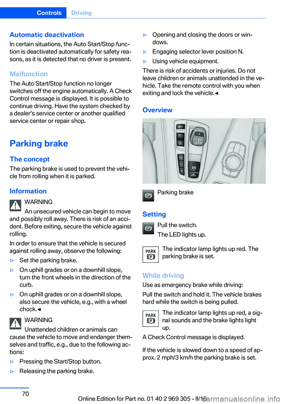
Parking brake
Setting Pull the switch.
The LED lights up.
The indicator lamp lights up red. The
parking brake is set.
While driving
Use as emergency brake while driving:
Pull the switch and hold it. The vehicle brakes
hard while the switch is being pulled.
The indicator lamp lights up red, a sig‐
nal sounds and the brake lights light
up.
A Check Control message is displayed.
If the vehicle is slowed down to a speed of ap‐
prox. 2 mph/3 km/h the parking brake is set.
Seite 70ControlsDriving70
Online Edition for Part no. 01 40 2 969 305 - II/16
Page 82 of 261
▷Messages, e.g. Check Control, refer to
page 85.▷Current fuel consumption, refer to
page 90.▷Navigation display, see Owner's Manual for
Navigation, Entertainment and Communi‐
cation.▷Range, refer to page 90.▷Status, Driving Dynamics Control, refer to
page 137.▷Service requirements, refer to page 91.▷Speed limit detection, refer to page 92.▷Time, refer to page 90.
Multifunctional instrument display
The concept
The instrument display is a variable display. In
the event of a program change, the display
rendition adapts to the respective program
through the Driving Dynamics Control. The
change of the display type can be deactivated
via iDrive.Some of the displays in the instrument display
may differ from the way they are shown in this
Owner's Manual.
Overview
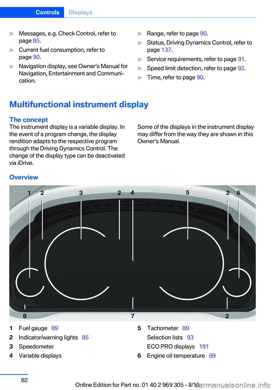
1Fuel gauge 892Indicator/warning lights 853Speedometer4Variable displays5Tachometer 89
Selection lists 93
ECO PRO displays 1916Engine oil temperature 89Seite 82ControlsDisplays82
Online Edition for Part no. 01 40 2 969 305 - II/16
Page 85 of 261
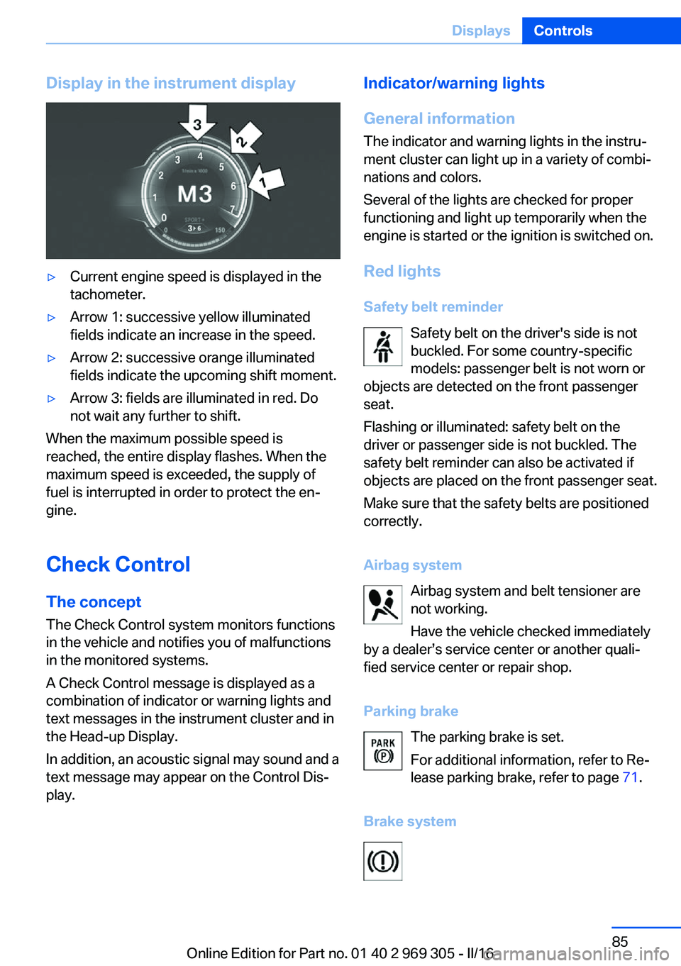
Display in the instrument display▷Current engine speed is displayed in the
tachometer.▷Arrow 1: successive yellow illuminated
fields indicate an increase in the speed.▷Arrow 2: successive orange illuminated
fields indicate the upcoming shift moment.▷Arrow 3: fields are illuminated in red. Do
not wait any further to shift.
When the maximum possible speed is
reached, the entire display flashes. When the
maximum speed is exceeded, the supply of
fuel is interrupted in order to protect the en‐
gine.
Check Control The conceptThe Check Control system monitors functions
in the vehicle and notifies you of malfunctions
in the monitored systems.
A Check Control message is displayed as a
combination of indicator or warning lights and
text messages in the instrument cluster and in
the Head-up Display.
In addition, an acoustic signal may sound and a
text message may appear on the Control Dis‐
play.
Indicator/warning lights
General information
The indicator and warning lights in the instru‐
ment cluster can light up in a variety of combi‐
nations and colors.
Several of the lights are checked for proper
functioning and light up temporarily when the
engine is started or the ignition is switched on.
Red lights
Safety belt reminder Safety belt on the driver's side is not
buckled. For some country-specific
models: passenger belt is not worn or
objects are detected on the front passenger
seat.
Flashing or illuminated: safety belt on the
driver or passenger side is not buckled. The
safety belt reminder can also be activated if
objects are placed on the front passenger seat.
Make sure that the safety belts are positioned
correctly.
Airbag system Airbag system and belt tensioner are
not working.
Have the vehicle checked immediately
by a dealer’s service center or another quali‐
fied service center or repair shop.
Parking brake The parking brake is set.
For additional information, refer to Re‐
lease parking brake, refer to page 71.
Brake systemSeite 85DisplaysControls85
Online Edition for Part no. 01 40 2 969 305 - II/16
Page 87 of 261
Dynamic Traction Control DTC, refer to
page 134.
Flat Tire Monitor FTM The Flat Tire Monitor signals a loss of
tire inflation pressure in a tire.
Reduce your speed and stop cau‐
tiously. Avoid sudden braking and steering ma‐
neuvers.
For more information, see Flat Tire Monitor, re‐
fer to page 112.
Tire Pressure Monitor TPM Illuminated: the Tire Pressure Monitor
signals a loss of tire inflation pressure
in a tire.
Reduce your speed and stop cautiously. Avoid
sudden braking and steering maneuvers.
Flashing and then continuously illuminated: no
flat tire or loss of tire inflation pressure can be
detected.▷Interference through systems or devices
with the same radio frequency: After leav‐
ing the area of the interference, the system
automatically becomes active again.▷TPM was unable to complete the reset.
Reset the system again.▷A wheel without TPM electronics is
mounted: Have it checked by a dealer’s
service center or another qualified service
center or repair shop as needed.▷Malfunction: have the system checked by a
dealer’s service center or another qualified
service center or repair shop.
For more information, see Tire Pressure Moni‐
tor, refer to page 108.
Steering system Steering system in some cases not
working.
Have the steering system checked by a
dealer’s service center or another qualified
service center or repair shop.
Engine functions Have the vehicle checked by a dealer’s
service center or another qualified
service center or repair shop.
For additional information, refer to On-board
Diagnostics socket, refer to page 227.
Lane departure warning System is switched on and under cer‐
tain circumstances warns if a detected
lane is left without flashing beforehand.
For additional information, refer to Lane depar‐
ture warning, refer to page 126.
Green lights Turn signal Turn signal switched on.
Unusually rapid flashing of the indicator
lamp indicates that a turn signal bulb
has failed.
For additional information, refer to Turn signal,
refer to page 73.
Parking lights, headlight control Parking lights or headlights are acti‐
vated.
For additional information, refer to
Parking lights/low beams, headlamp control,
refer to page 100.
Front fog lights Front fog lights are activated.
For additional information, refer to
Front fog lights, refer to page 103.Seite 87DisplaysControls87
Online Edition for Part no. 01 40 2 969 305 - II/16
Page 88 of 261
High-beam AssistantHigh-beam Assistant is switched on.
High beams are activated and off auto‐
matically as a function of the traffic sit‐
uation.
For additional information, refer to High-beam
Assistant, refer to page 103.
Cruise control The system is switched on. It maintains
the speed that was set using the con‐
trol elements on the steering wheel.
Automatic Hold Function is activated. The vehicle is au‐
tomatically held in place when it is sta‐
tionary.
For more information, see Automatic Hold, re‐
fer to page 71.
Blue lights
High beams High beams are activated.
For additional information, refer to High
beams, refer to page 73.
General lamps
Check Control At least one Check Control message is
displayed or is stored.
Text messages Text messages in combination with a symbol
in the instrument cluster explain a Check Con‐
trol message and the meaning of the indicator
and warning lights.Supplementary text messages
Additional information, such as on the cause of
an error or the required action, can be called up
via Check Control.
With urgent messages the added text will be
automatically displayed on the Control Display.
Symbols
Depending on the Check Control message, the
following functions can be selected.▷ "Owner's Manual"
Display additional information about the
Check Control message in the Integrated
Owner's Manual.▷ "Service request"
Contact a dealer’s service center or an‐
other qualified service center or repair
shop.▷ "Roadside Assistance"
Contact Roadside Assistance.
Hiding Check Control messages
Press and hold button on turn signal lever.
▷Some Check Control messages are dis‐
played continuously and are not cleared
until the malfunction is eliminated. If sev‐
eral malfunctions occur at once, the mes‐
sages are displayed consecutively.
These messages can be faded for approx.
8 seconds. After this time, they are dis‐
played again automatically.Seite 88ControlsDisplays88
Online Edition for Part no. 01 40 2 969 305 - II/16
Page 114 of 261
maneuvers or driving over obstacles, for exam‐
ple, curbs, potholes, etc.
Because the possible driving distance de‐
pends on how the vehicle is used during the
trip, the actual distance may be shorter or lon‐
ger depending on the driving speed, road con‐
ditions, external temperature, cargo load, etc.
WARNING
Your vehicle handles differently when a
run-flat tire is damaged and has low or missing
tire inflation pressure, e.g., your lane stability is
reduced when braking, braking distances are
longer and the self-steering properties will
change. There is risk of an accident.
Drive moderately and do not exceed a speed of
50 mph/80 km/h.◀
Final tire failure
Vibrations or loud noises while driving can indi‐
cate the final failure of a tire.
Reduce speed and stop; otherwise, pieces of
the tire could come loose and cause an acci‐
dent.
Do not continue driving. Contact a dealer’s
service center or another qualified service cen‐
ter or repair shop.
Intelligent Safety The concept
Intelligent Safety enables central operation of
the driver assistance system.
Depending on how the vehicle is equipped, In‐
telligent Safety consists of one or more sys‐
tems that can help prevent a imminent colli‐
sion. These systems are active automatically
every time the engine is started using the
Start/Stop button:▷Front-end collision warning, refer to
page 115.▷Pedestrian warning, refer to page 120.Information
WARNING
Indicators and warnings do not relieve
the driver from personal responsibility. Due to
system limits, warnings or reactions of the sys‐
tem may not be output or they may be output
too late or incorrectly. There is risk of an acci‐
dent. Adjust the driving style to the traffic con‐
ditions. Watch traffic closely and actively inter‐
vene in the respective situations.◀
WARNING
Due to system limits, individual functions
can malfunction during tow-starting/towing
with the Intelligent Safety systems activated,
e.g., approach control warning with light brak‐
ing function. There is risk of an accident.
Switch all Intelligent Safety systems off prior to
tow-starting/towing.◀
Overview
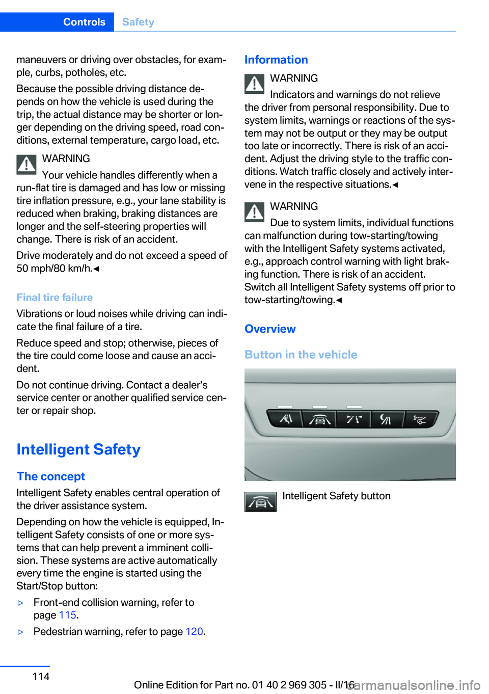
Button in the vehicle
Intelligent Safety button
Seite 114ControlsSafety114
Online Edition for Part no. 01 40 2 969 305 - II/16
Page 209 of 261
cantly from the norm due to variations in driv‐
ing habits, service practices and differences in
road characteristics and climate.
Traction
The traction grades, from highest to lowest,
are AA, A, B, and C.
Those grades represent the tire's ability to
stop on wet pavement as measured under
controlled conditions on specified government
test surfaces of asphalt and concrete. A tire
marked C may have poor traction performance.
The traction grade assigned to this tire is
based on straight-ahead braking traction tests,
and does not include acceleration, cornering,
hydroplaning, or peak traction characteristics.
Temperature
The temperature grades are A, the highest, B, and C, representing the tire's resistance to the
generation of heat and its ability to dissipate
heat when tested under controlled conditions
on a specified indoor laboratory test wheel.
Sustained high temperature can cause the ma‐
terial of the tire to degenerate and reduce tire
life, and excessive temperature can lead to
sudden tire failure. The grade C corresponds
to a level of performance which all passenger
car tires must meet under the Federal Motor
Vehicle Safety Standard No. 109. Grades Band
A represent higher levels of performance on
the laboratory test wheel than the minimum re‐
quired by law.
WARNING
The temperature grade for this tire is es‐
tablished for a tire that is properly inflated and
not overloaded. Excessive speed, underinfla‐
tion, or excessive loading, either separately or
in combination, can cause heat buildup and
possible tire failure.◀RSC – Run-flat tires
Run-flat tires, refer to page 212, are labeled
with a circular symbol containing the letters
RSC marked on the sidewall.
M+S Winter and all-season tires with better cold
weather performance than summer tires.
Tire tread Summer tires
Do not drive with a tire tread depth of less than
0.12 inches/3 mm.
There is an increased danger of hydroplaning if
the tire tread depth is less than 0.12 in‐
ches/3 mm.
Winter tires
Do not drive with a tire tread depth of less than
0.16 inches/4 mm.
Below a tread depth of 0.16 inches/4 mm, tires
are less suitable for winter operation.
Minimum tread depth
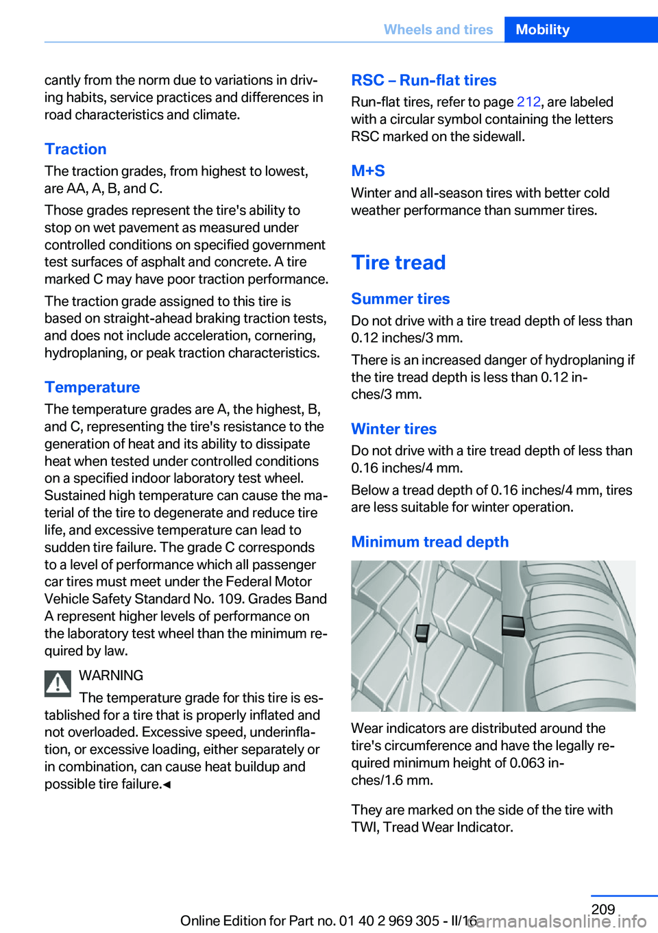
Wear indicators are distributed around the
tire's circumference and have the legally re‐
quired minimum height of 0.063 in‐
ches/1.6 mm.
They are marked on the side of the tire with
TWI, Tread Wear Indicator.
Seite 209Wheels and tiresMobility209
Online Edition for Part no. 01 40 2 969 305 - II/16
Page 229 of 261
service center or repair shop if you are unfami‐
liar with it or if it has not been described here.
A spare lamp box is available from a dealer’s
service center or another qualified service cen‐
ter or repair shop.
WARNING
Bulbs can get hot during operation. Con‐
tact with the bulbs can cause burns. There is a
risk of injuries. Only change bulbs after they
have cooled off.◀
WARNING
Work on switched-on lighting systems
can cause short circuits. There is a risk of inju‐
ries or a risk of property damage. When work‐
ing on the lighting system, switch off the lamps
in question. If necessary, heed the bulb manu‐
facturer's instructions.◀
CAUTION
Dirty bulbs have a reduced service life.
There is a risk of property damage. Do not hold
new bulbs with your bare hands. Use a clean
cloth or something similar, or hold the bulb by
its base.◀
Light-emitting diodes (LEDs)
Some items of equipment use light-emitting
diodes installed behind a cover as a light
source.
These light-emitting diodes, which are related
to conventional lasers, are officially designated as Class 1 light-emitting diodes.
WARNING
Too intensive brightness can irritate or
damage the retina of the eye. There is a a risk
of injury. Do not look directly into the head‐
lights or other light sources. Do not remove the LED covers.◀
Headlight glass
Condensation can form on the inside of the ex‐
ternal lights in cool or humid weather. Whendriving with the lights switched on, the con‐
densation evaporates after a short time. The
headlight glass does not need to be changed.
If despite driving with the lights switched on,
increasing humidity forms, e. g. water droplets
in the lamp, the manufacturer of your vehicle
recommends having it checked by a dealer’s
service center or another qualified service cen‐
ter or repair shop.
Headlight setting
The headlight adjustments can be affected by
changing lights and bulbs. After the headlight
adjustment was changed, have it checked and,
if necessary, corrected by a dealer’s service
center or another qualified service center or re‐ pair shop.
Front lights, bulb replacement
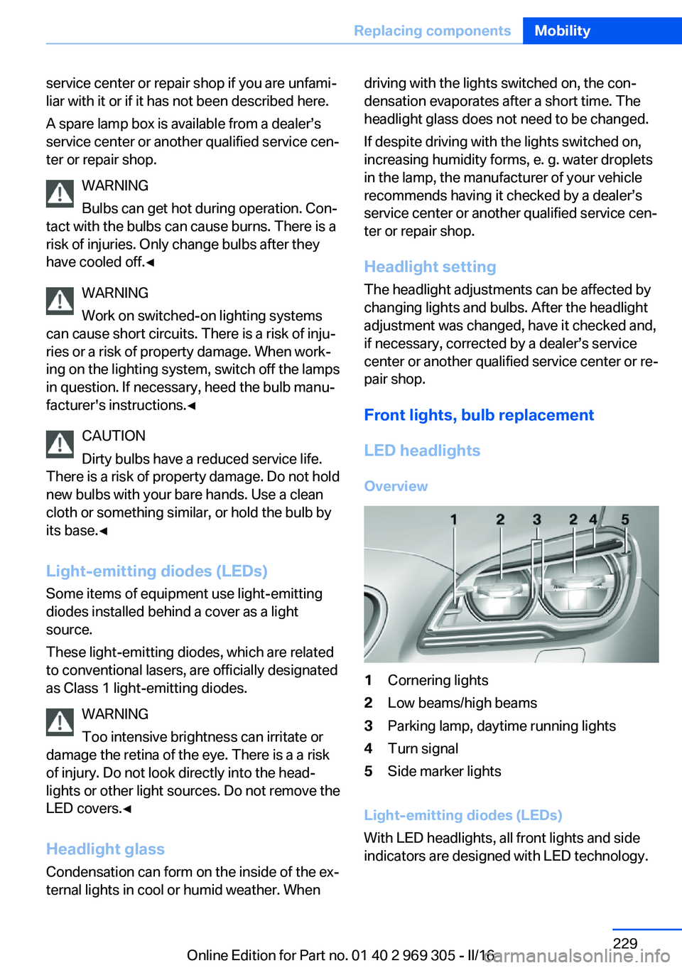
LED headlights Overview1Cornering lights2Low beams/high beams3Parking lamp, daytime running lights4Turn signal5Side marker lights
Light-emitting diodes (LEDs)
With LED headlights, all front lights and side
indicators are designed with LED technology.
Seite 229Replacing componentsMobility229
Online Edition for Part no. 01 40 2 969 305 - II/16
Page 252 of 261
COMFORT program, DrivingDynamics Control 139
Compressor 212
Condensation on win‐ dows 165
Condensation under the vehi‐ cle 187
Condition Based Service CBS 226
Configure driving mode 140
Confirmation signal 44
ConnectedDrive, see Owner's Manual for Navigation, En‐
tertainment and Communi‐
cation
ConnectedDrive Services
Container for washer fluid 76
Continued driving with a flat tire 110 , 113
Control Display 18
Control Display, settings 96
Controller 19
Control systems, driving sta‐ bility 133
Convenient opening with the remote control 38
Coolant 224
Coolant level 224
Coolant temperature 89
Cooling function 163
Cooling, maximum 163
Cooling system 224
Cornering light 102
Corrosion on brake discs 186
Cosmetic mirror 171
Courtesy lamps during un‐ locking 38
Courtesy lamps with the vehi‐ cle locked 38
Cruise control 147
Cruise control, active with Stop&Go function 141
Cruise control with distance control, see active cruise
control, ACC 141 Cruise control without dis‐
tance control, see cruise
control 147
Cruising range 90
Cup holder 179
Current fuel consumption 90
D
Damage, tires 210
Damping control, dy‐ namic 136
Data, technical 246
Date 90
Daytime running lights 102
Defrosting, see Windows, de‐ frosting 165
Dehumidifying, air 163
Deleting personal data 24
Deletion of personal data 24
Destination distance 95
Digital clock 90
Dimensions 246
Dimmable exterior mirrors 59
Dimmable interior mirror 60
Direction indicator, see Turn signals 73
Display, electronic, instru‐ ment cluster 81
Display in windshield 98
Display lighting, see Instru‐ ment lighting 104
Displays 82
Displays, cleaning 242
Disposal, coolant 225
Disposal, vehicle battery 232
Distance control, see PDC 150
Distance to destination 95
Divided screen view, split screen 23
Door lock 39
Door lock, see Remote con‐ trol 34
Doors, Automatic Soft Clos‐ ing 41 Downhill control 135
Drive mode 137
Drive-off assistant 133
Drive-off assistant, see DSC 133
Driver assistance, see Intelli‐ gent Safety 114
Driving Assistant, see Intelli‐ gent Safety 114
Driving Dynamics Con‐ trol 137
Driving instructions, break- in 184
Driving notes, general 184
Driving on racetracks 187
Driving stability control sys‐ tems 133
Driving tips 184
DSC Dynamic Stability Con‐ trol 133
DTC Dynamic Traction Con‐ trol 134
Dynamic Damping Con‐ trol 136
Dynamic Drive 136
Dynamic Stability Control DSC 133
Dynamic Traction Control DTC 134
E
ECO PRO 191
ECO PRO, bonus range 192
ECO PRO display 191
ECO PRO displays 83
ECO PRO driving mode 191
ECO PRO mode 191
ECO PRO Tip - driving in‐ struction 193
EfficientDynamics 193
Electronic displays, instru‐ ment cluster 81
Electronic oil measure‐ ment 220 Seite 252ReferenceEverything from A to Z252
Online Edition for Part no. 01 40 2 969 305 - II/16