park assist BMW 640I COUPE 2013 Owners Manual
[x] Cancel search | Manufacturer: BMW, Model Year: 2013, Model line: 640I COUPE, Model: BMW 640I COUPE 2013Pages: 232, PDF Size: 8.98 MB
Page 12 of 232
CockpitVehicle equipment
All standard, country-specific and optional
equipment that is offered in the model series is
described in this chapter. Therefore, equipmentis also described that is not available in a vehicle,
e. g., because of the selected optional equip‐
ment or country variant. This also applies for
safety-related functions and systems.
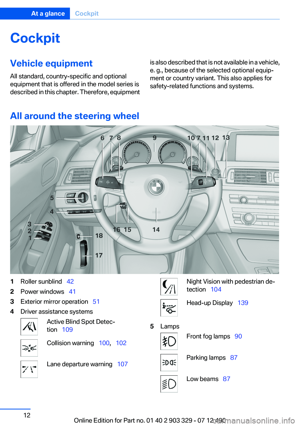
All around the steering wheel
1Roller sunblind 422Power windows 413Exterior mirror operation 514Driver assistance systemsActive Blind Spot Detec‐
tion 109Collision warning 100, 102Lane departure warning 107Night Vision with pedestrian de‐
tection 104Head-up Display 1395LampsFront fog lamps 90Parking lamps 87Low beams 87Seite 12At a glanceCockpit12
Online Edition for Part no. 01 40 2 903 329 - 07 12 490
Page 13 of 232
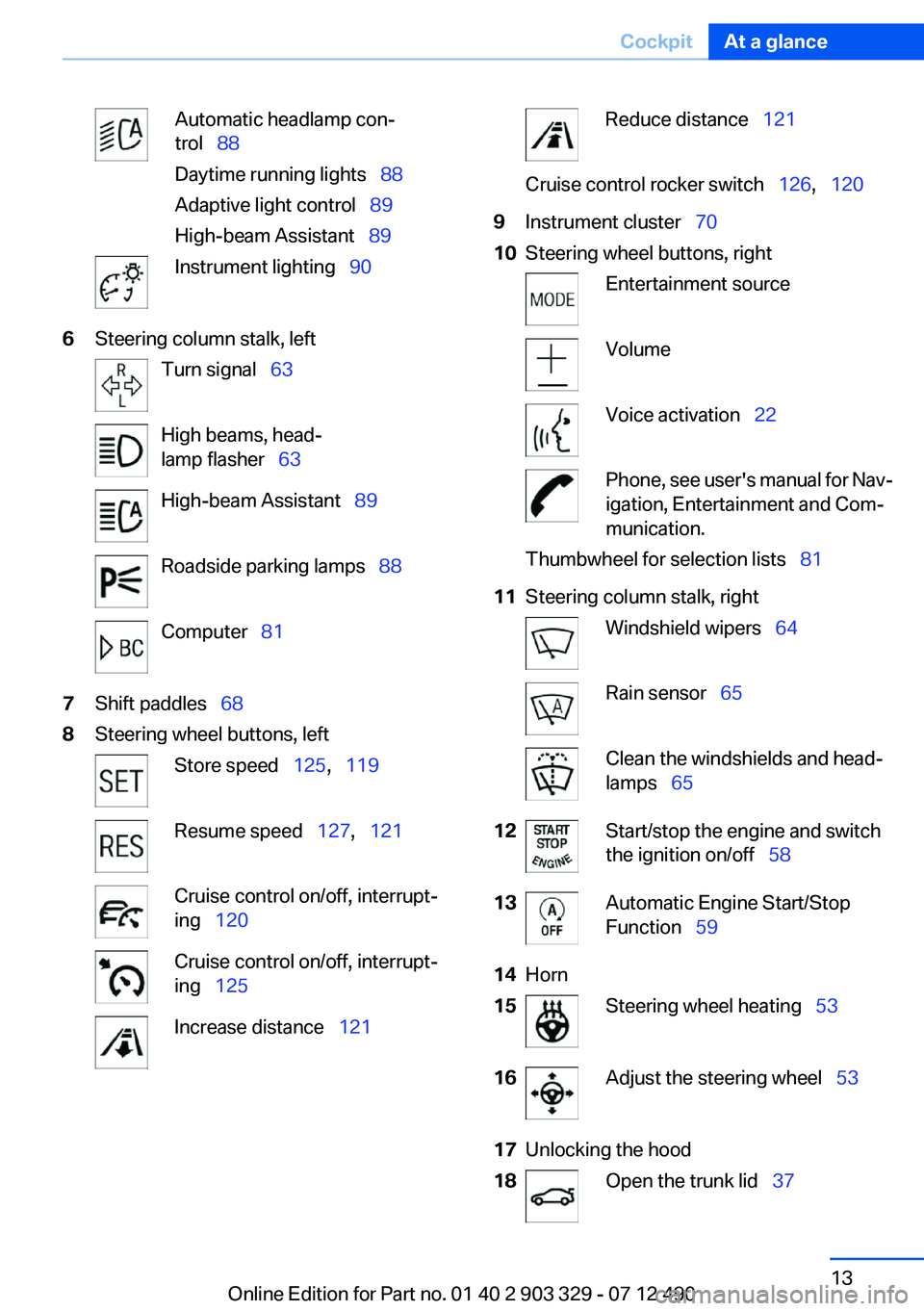
Automatic headlamp con‐
trol 88
Daytime running lights 88
Adaptive light control 89
High-beam Assistant 89Instrument lighting 906Steering column stalk, leftTurn signal 63High beams, head‐
lamp flasher 63High-beam Assistant 89Roadside parking lamps 88Computer 817Shift paddles 688Steering wheel buttons, leftStore speed 125, 119Resume speed 127, 121Cruise control on/off, interrupt‐
ing 120Cruise control on/off, interrupt‐
ing 125Increase distance 121Reduce distance 121Cruise control rocker switch 126, 1209Instrument cluster 7010Steering wheel buttons, rightEntertainment sourceVolumeVoice activation 22Phone, see user's manual for Nav‐
igation, Entertainment and Com‐
munication.Thumbwheel for selection lists 8111Steering column stalk, rightWindshield wipers 64Rain sensor 65Clean the windshields and head‐
lamps 6512Start/stop the engine and switch
the ignition on/off 5813Automatic Engine Start/Stop
Function 5914Horn15Steering wheel heating 5316Adjust the steering wheel 5317Unlocking the hood18Open the trunk lid 37Seite 13CockpitAt a glance13
Online Edition for Part no. 01 40 2 903 329 - 07 12 490
Page 14 of 232
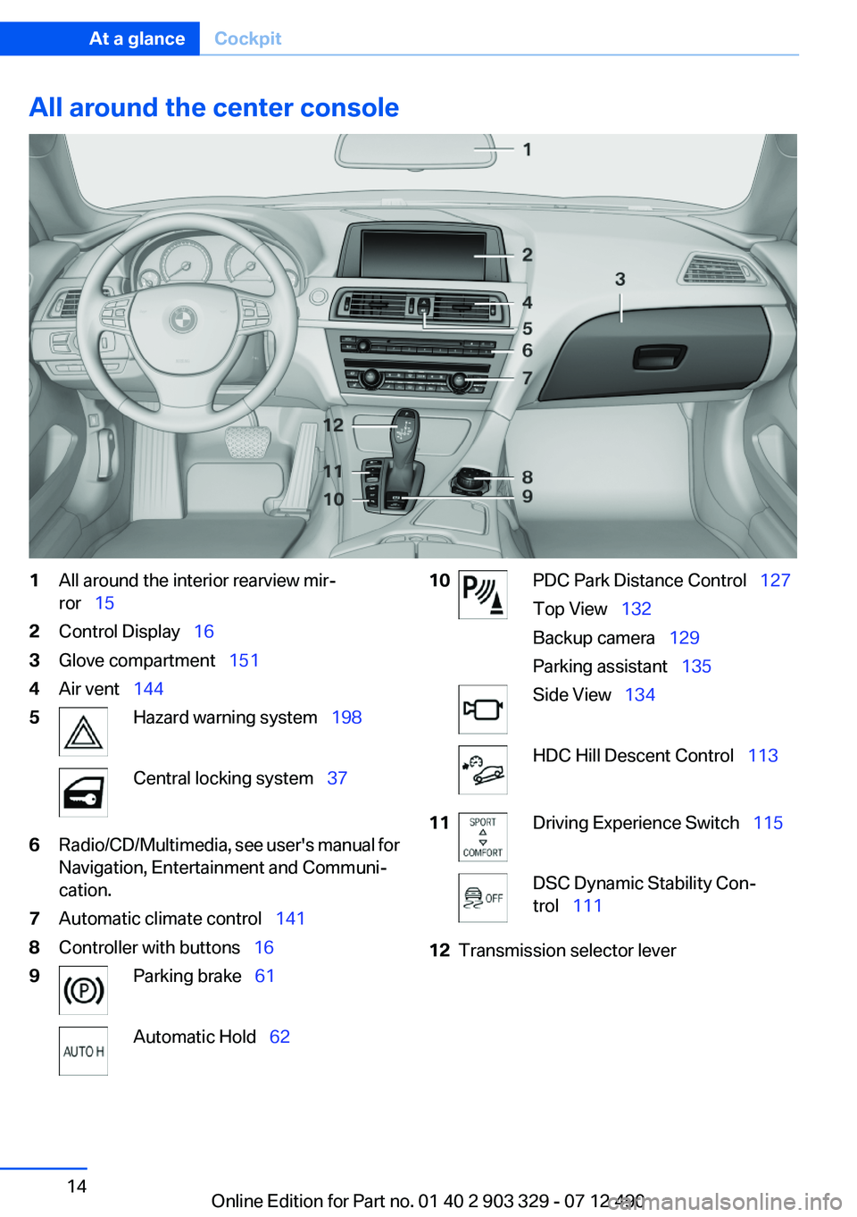
All around the center console1All around the interior rearview mir‐
ror 152Control Display 163Glove compartment 1514Air vent 1445Hazard warning system 198Central locking system 376Radio/CD/Multimedia, see user's manual for
Navigation, Entertainment and Communi‐
cation.7Automatic climate control 1418Controller with buttons 169Parking brake 61Automatic Hold 6210PDC Park Distance Control 127
Top View 132
Backup camera 129
Parking assistant 135Side View 134HDC Hill Descent Control 11311Driving Experience Switch 115DSC Dynamic Stability Con‐
trol 11112Transmission selector leverSeite 14At a glanceCockpit14
Online Edition for Part no. 01 40 2 903 329 - 07 12 490
Page 60 of 232
▷After driving in reverse.▷Fogging of the windows when the automatic
climate control is switched on.▷The vehicle battery charge is very low.▷The engine compartment lid is unlocked.▷HDC is activated.▷The parking assistant is activated.▷Stop-and-go traffic.▷The transmission selector lever is in position
N or S/M.
Starting the engine
The engine starts automatically under the fol‐
lowing conditions:
▷Manual transmission:
The clutch pedal is pressed.▷Automatic transmission:
By releasing the brake pedal.
When Automatic Hold is activated: press the
accelerator.
After the engine starts, accelerate as usual.
Safety mode
After the engine switches off automatically, it
will not start again automatically if any one of the
following conditions are met.
▷The driver's safety belt is unbuckled and the
driver's door is open.▷The hood was unlocked.
Some indicator lamps light up for varying
lengths of time.
The engine can only be started via the Start/
Stop button.
Note
Even if driving away was not intended, the de‐
activated engine starts up automatically in the
following situations:
▷Excessive warming of the passenger com‐
partment when the cooling function is
switched on.▷The steering wheel is turned.▷Automatic transmission: the transmission
position is changed from D to N, R, or M/S.▷Automatic transmission: the transmission
position is changed from P to N, D, R, or M/
S.▷Fogging of the windows when the automatic
climate control is switched on.▷The vehicle battery charge is very low.▷Excessive cooling of the passenger com‐
partment when the heating is switched on.
Preventing an automatic engine stop
with automatic transmission
The concept
To make it possible to drive away very quickly,
such as at an intersection, the automatic engine
stop can be actively prevented.
Preventing an engine stop using the
brake pedal
The engine stop can be actively prevented
within one second after the vehicle comes to a
standstill.
▷Immediately after the vehicle comes to a
standstill, briefly press the brake pedal
forcefully.▷Then press the brake pedal with normal
braking force.Seite 60ControlsDriving60
Online Edition for Part no. 01 40 2 903 329 - 07 12 490
Page 62 of 232
Pull the switch and hold it. The vehicle brakes
hard while the button is being pulled.
The indicator lamp lights up red, a signal
sounds and the brake lamps light up.
Lower lamp: indicator lamp in Canadian
models.
If the vehicle is braked to a speed of approx.
2 mph/3 km/h, the parking brake remains set.
Releasing
With the ignition switched on:
Manual transmission: Press the switch
while the brake or clutch is pressed.
Automatic transmission: Press the switch while
the brake is pressed or transmission position P
is engaged.
The LED and indicator lamp go out.
The parking brake is released.
Automatic Release
For automatic release, operate the accelerator
pedal.
The LED and indicator lamp go out.
Subject to the following requirements, the park‐
ing brake is automatically released by operation
of the accelerator pedal:▷Engine on.▷Drive position engaged.▷Driver buckled in and doors closed.
Inadvertent operation of the accelerator
pedal
Make sure that the accelerator pedal is not op‐
erated unintentionally; otherwise, the vehicle is
set in motion and there is a risk of an accident. ◀
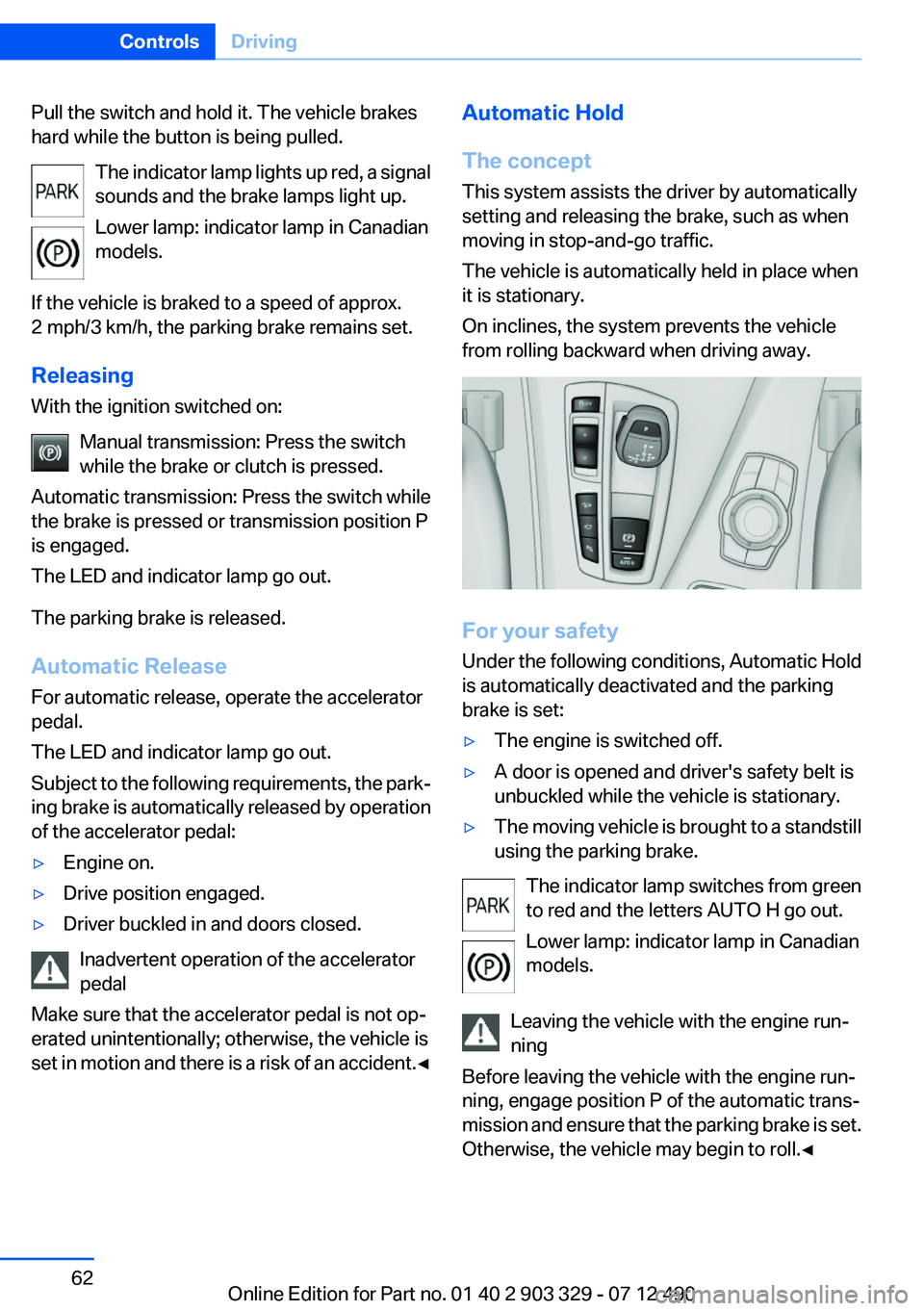
Automatic Hold
The concept
This system assists the driver by automatically
setting and releasing the brake, such as when
moving in stop-and-go traffic.
The vehicle is automatically held in place when
it is stationary.
On inclines, the system prevents the vehicle
from rolling backward when driving away.
For your safety
Under the following conditions, Automatic Hold
is automatically deactivated and the parking
brake is set:
▷The engine is switched off.▷A door is opened and driver's safety belt is
unbuckled while the vehicle is stationary.▷The moving vehicle is brought to a standstill
using the parking brake.
The indicator lamp switches from green
to red and the letters AUTO H go out.
Lower lamp: indicator lamp in Canadian
models.
Leaving the vehicle with the engine run‐
ning
Before leaving the vehicle with the engine run‐
ning, engage position P of the automatic trans‐
mission and ensure that the parking brake is set.
Otherwise, the vehicle may begin to roll.◀
Seite 62ControlsDriving62
Online Edition for Part no. 01 40 2 903 329 - 07 12 490
Page 75 of 232
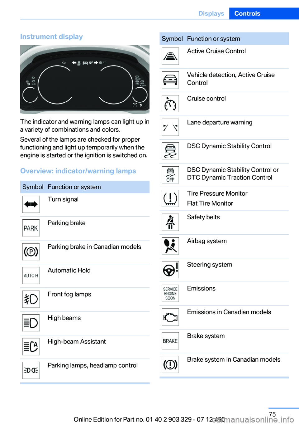
Instrument display
The indicator and warning lamps can light up in
a variety of combinations and colors.
Several of the lamps are checked for proper
functioning and light up temporarily when the
engine is started or the ignition is switched on.
Overview: indicator/warning lamps
SymbolFunction or systemTurn signalParking brakeParking brake in Canadian modelsAutomatic HoldFront fog lampsHigh beamsHigh-beam AssistantParking lamps, headlamp controlSymbolFunction or systemActive Cruise ControlVehicle detection, Active Cruise
ControlCruise controlLane departure warningDSC Dynamic Stability ControlDSC Dynamic Stability Control or
DTC Dynamic Traction ControlTire Pressure Monitor
Flat Tire MonitorSafety beltsAirbag systemSteering systemEmissionsEmissions in Canadian modelsBrake systemBrake system in Canadian modelsSeite 75DisplaysControls75
Online Edition for Part no. 01 40 2 903 329 - 07 12 490
Page 87 of 232
LampsVehicle equipment
All standard, country-specific and optional
equipment that is offered in the model series is
described in this chapter. Therefore, equipment
is also described that is not available in a vehicle,
e. g., because of the selected optional equip‐
ment or country variant. This also applies for
safety-related functions and systems.
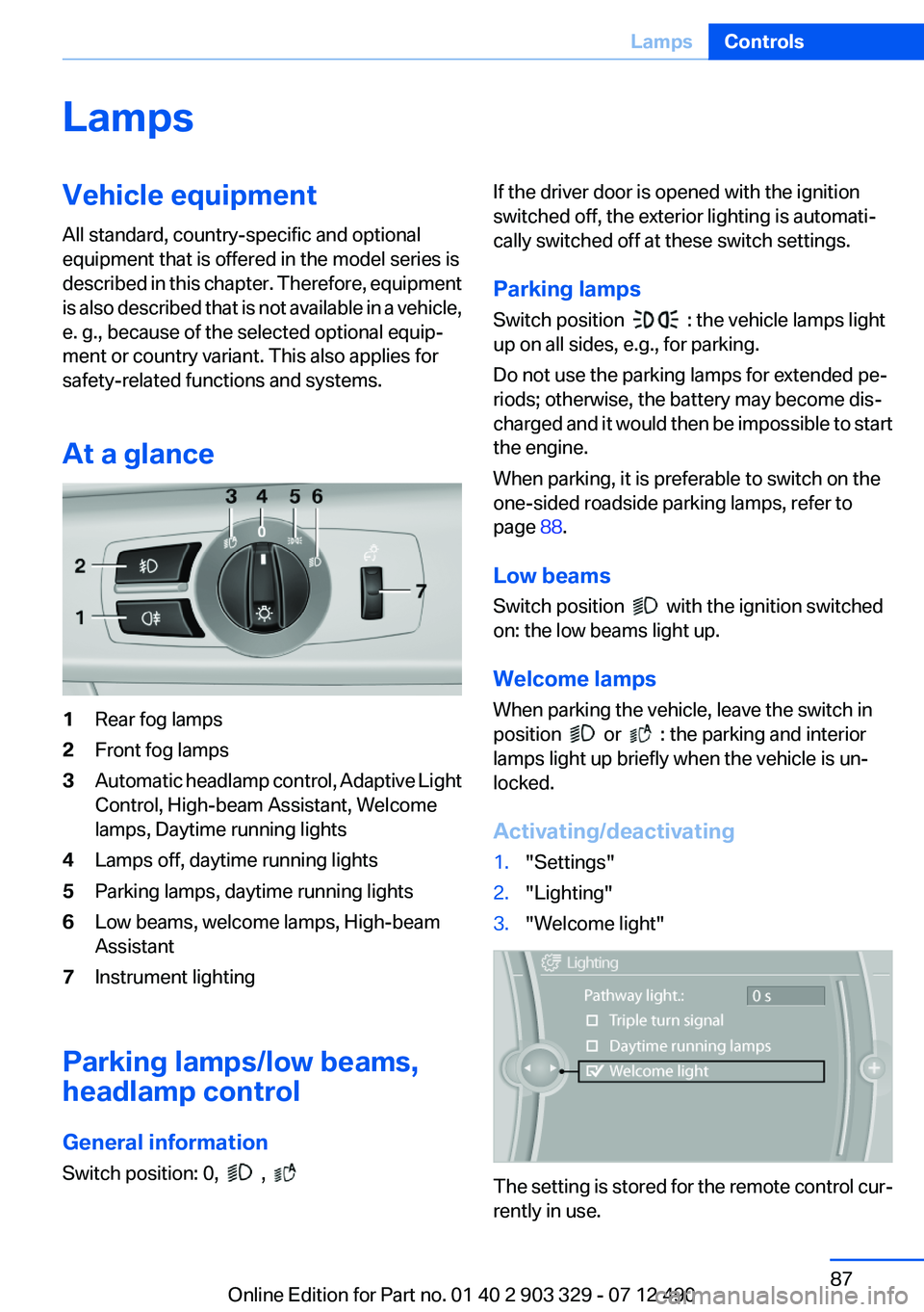
At a glance1Rear fog lamps2Front fog lamps3Automatic headlamp control, Adaptive Light
Control, High-beam Assistant, Welcome
lamps, Daytime running lights4Lamps off, daytime running lights5Parking lamps, daytime running lights6Low beams, welcome lamps, High-beam
Assistant7Instrument lighting
Parking lamps/low beams,
headlamp control
General information
Switch position: 0,
,
If the driver door is opened with the ignition
switched off, the exterior lighting is automati‐
cally switched off at these switch settings.
Parking lamps
Switch position
: the vehicle lamps light
up on all sides, e.g., for parking.
Do not use the parking lamps for extended pe‐
riods; otherwise, the battery may become dis‐
charged and it would then be impossible to start
the engine.
When parking, it is preferable to switch on the
one-sided roadside parking lamps, refer to
page 88.
Low beams
Switch position
with the ignition switched
on: the low beams light up.
Welcome lamps
When parking the vehicle, leave the switch in
position
or : the parking and interior
lamps light up briefly when the vehicle is un‐
locked.
Activating/deactivating
1."Settings"2."Lighting"3."Welcome light"
The setting is stored for the remote control cur‐
rently in use.
Seite 87LampsControls87
Online Edition for Part no. 01 40 2 903 329 - 07 12 490
Page 90 of 232
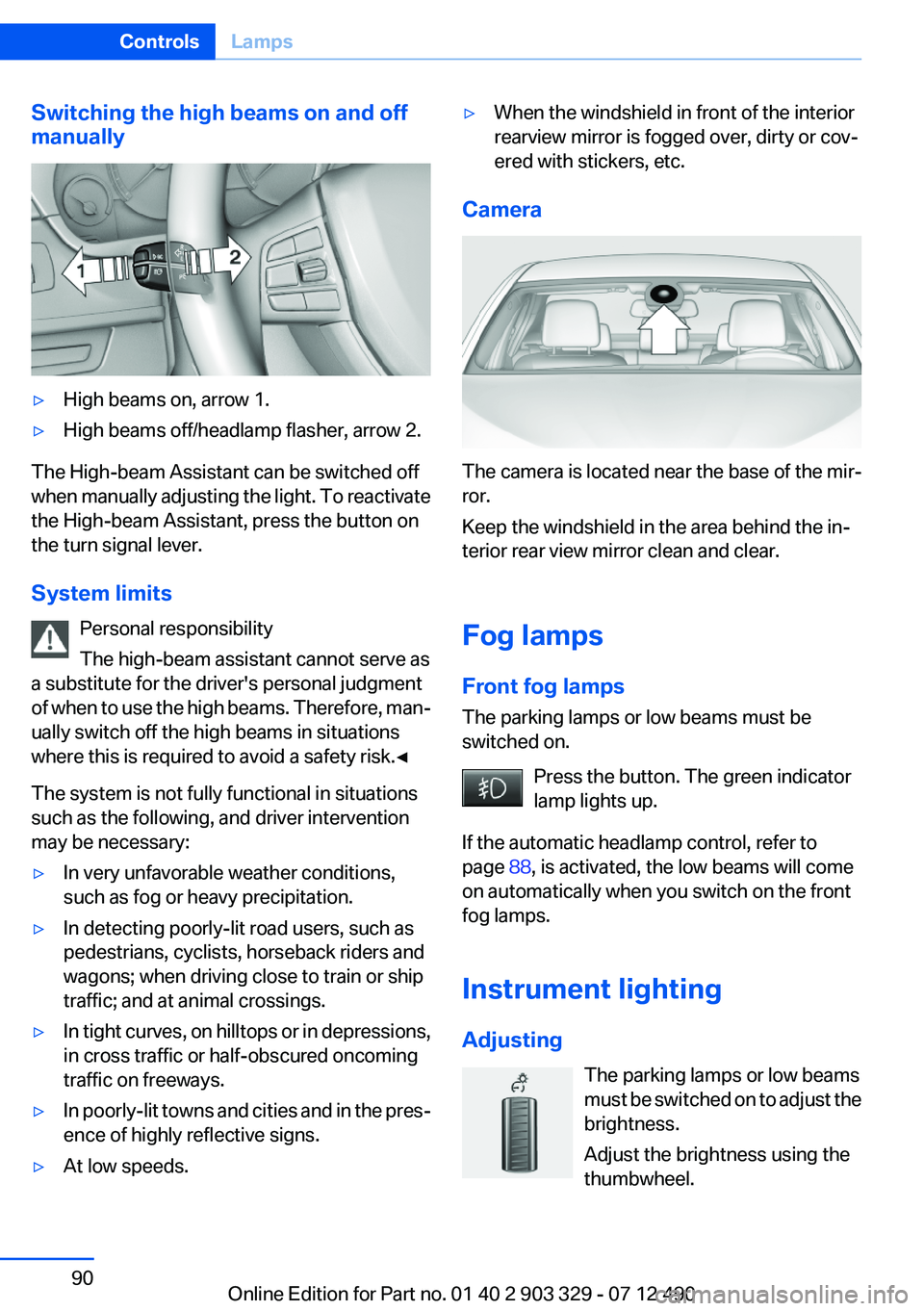
Switching the high beams on and off
manually▷High beams on, arrow 1.▷High beams off/headlamp flasher, arrow 2.
The High-beam Assistant can be switched off
when manually adjusting the light. To reactivate
the High-beam Assistant, press the button on
the turn signal lever.
System limits Personal responsibility
The high-beam assistant cannot serve as
a substitute for the driver's personal judgment
of when to use the high beams. Therefore, man‐
ually switch off the high beams in situations
where this is required to avoid a safety risk.◀
The system is not fully functional in situations
such as the following, and driver intervention
may be necessary:
▷In very unfavorable weather conditions,
such as fog or heavy precipitation.▷In detecting poorly-lit road users, such as
pedestrians, cyclists, horseback riders and
wagons; when driving close to train or ship
traffic; and at animal crossings.▷In tight curves, on hilltops or in depressions,
in cross traffic or half-obscured oncoming
traffic on freeways.▷In poorly-lit towns and cities and in the pres‐
ence of highly reflective signs.▷At low speeds.▷When the windshield in front of the interior
rearview mirror is fogged over, dirty or cov‐
ered with stickers, etc.
Camera
The camera is located near the base of the mir‐
ror.
Keep the windshield in the area behind the in‐
terior rear view mirror clean and clear.
Fog lamps
Front fog lamps
The parking lamps or low beams must be
switched on.
Press the button. The green indicator
lamp lights up.
If the automatic headlamp control, refer to
page 88, is activated, the low beams will come
on automatically when you switch on the front
fog lamps.
Instrument lighting
Adjusting The parking lamps or low beams
must be switched on to adjust the
brightness.
Adjust the brightness using the
thumbwheel.
Seite 90ControlsLamps90
Online Edition for Part no. 01 40 2 903 329 - 07 12 490
Page 111 of 232
Driving stability control systemsVehicle equipment
All standard, country-specific and optional
equipment that is offered in the model series is
described in this chapter. Therefore, equipment
is also described that is not available in a vehicle,
e. g., because of the selected optional equip‐
ment or country variant. This also applies for
safety-related functions and systems.
Antilock Brake System ABS
ABS prevents locking of the wheels during brak‐
ing.
The vehicle remains steerable even during full
brake applications, thus increasing active
safety.
ABS is operational every time you start the en‐
gine.
Brake assistant
When you apply the brakes rapidly, this system
automatically produces the maximum braking
force boost. It thus helps to achieve the shortest
possible braking distance during full braking.
This system utilizes all of the benefits provided
by ABS.
Do not reduce the pressure on the brake pedal
for the duration of the full braking.
Adaptive brake assistant
In combination with the Active Cruise Control,
this system ensures that the brakes respond
even more rapidly when braking in critical situa‐
tions. Refer also to Collision warning, refer to
page 102.Drive-off assistant
This system supports driving away on gradients.
The parking brake is not required.1.Hold the vehicle in place with the foot brake.2.Release the foot brake and drive away with‐
out delay.
After the foot brake is released, the vehicle is
held in place for approx. 2 seconds.
Depending on the vehicle load, the vehicle may
roll back slightly.
Driving off without delay
After releasing the foot brake, start driving
without delay, since the drive-off assistant will
not hold the vehicle in place for more than ap‐
prox. 2 seconds and the vehicle will begin rolling
back.◀
DSC Dynamic Stability
Control
The concept
DSC prevents traction loss in the driving wheels
when driving away and accelerating.
DSC also recognizes unstable vehicle condi‐
tions, such as fishtailing or nose-diving. Subject
to physical limits, DSC helps to keep the vehicle
on a steady course by reducing engine speed
and by applying brakes at individual wheels.
Adjust your driving style to the situation
An appropriate driving style is always the
responsibility of the driver.
The laws of physics cannot be repealed, even
with DSC.
Therefore, do not reduce the additional safety
margin by driving in a risky manner.◀
Seite 111Driving stability control systemsControls111
Online Edition for Part no. 01 40 2 903 329 - 07 12 490
Page 129 of 232
The range of the sensors is represented in col‐
ors: red, green and yellow.
If the backup camera image was selected last, it
again appears on the display. To switch to PDC:1. "Rear view camera" Select the symbol
on the Control Display.2.Press the controller.
The setting is stored for the remote control cur‐
rently in use.
System limits
Limits of ultrasonic measurement
The detection of objects can reach the physical
limits of ultrasonic measurement, e.g.:
▷With tow bars and trailer hitches.▷With thin or wedge-shaped objects.▷With low objects.▷With objects with corners and sharp edges.
Low objects already displayed, e.g., curbs, can
move into the blind area of the sensors before or
after a continuous tone sounds.
High, protruding objects such as ledges may not
be detected.
False warnings
PDC may issue a warning under the following
conditions even though there is no obstacle
within the detection range:
▷In heavy rain.▷When sensors are very dirty or covered in
ice.▷When sensors are covered in snow.▷On rough road surfaces.▷In large buildings with right angles and
smooth walls, e.g., in underground garages.▷In heavy exhaust.▷Due to other ultrasound sources, e.g.,
sweeping machines, high pressure steam
cleaners or neon lights.Malfunction
A Check Control message is displayed.
The range of the sensors is shown as a shaded
area on the Control Display.
PDC has failed. Have the system checked.
To ensure full operability:▷Keep the sensors clean and free of ice.▷When using high-pressure washers, do not
spray the sensors for long periods and main‐
tain a distance of at least 12 in/30 cm.
Surround View
The concept
Surround View includes the following systems:
▷Backup camera, refer to page 129.▷Side View, refer to page 134.▷Top View, refer to page 132.
It assists the driver when parking, maneuvering
and on blind driveways and intersections.
Backup camera
The concept
The backup camera provides assistance in park‐
ing and maneuvering backwards. The area be‐
hind the vehicle is shown on the Control Display.
Notes Check the traffic situation as well
Check the traffic situation around the ve‐
hicle with your own eyes. Otherwise, an accident
could result from road users or objects located
outside the picture area of the backup camera. ◀
Seite 129Driving comfortControls129
Online Edition for Part no. 01 40 2 903 329 - 07 12 490