navigation system BMW 650I 2012 F12 Owner's Guide
[x] Cancel search | Manufacturer: BMW, Model Year: 2012, Model line: 650I, Model: BMW 650I 2012 F12Pages: 282, PDF Size: 8.25 MB
Page 79 of 282
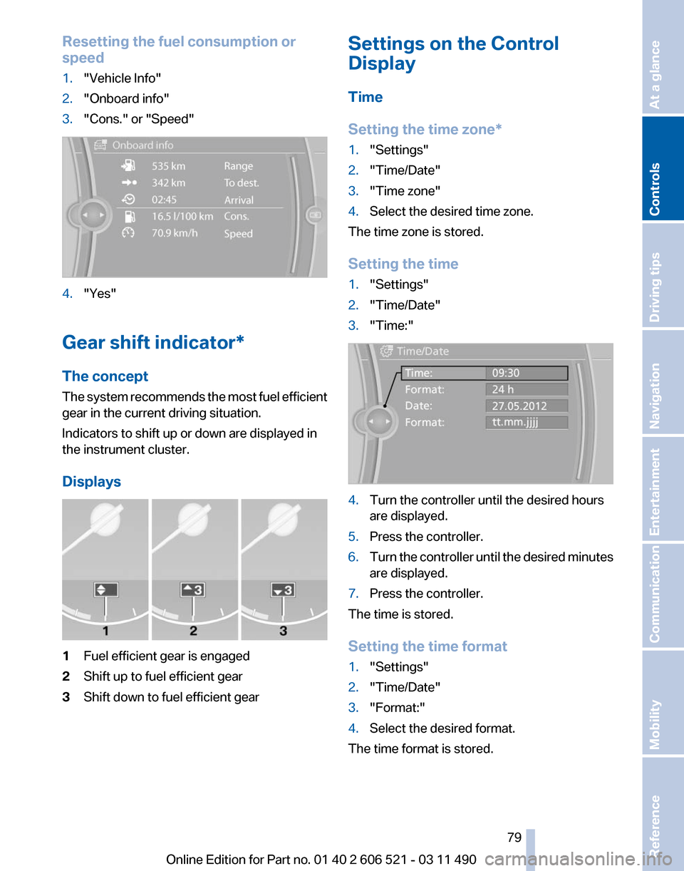
Resetting the fuel consumption or
speed
1.
"Vehicle Info"
2. "Onboard info"
3. "Cons." or "Speed" 4.
"Yes"
Gear shift indicator*
The concept
The
system recommends the most fuel efficient
gear in the current driving situation.
Indicators to shift up or down are displayed in
the instrument cluster.
Displays 1
Fuel efficient gear is engaged
2 Shift up to fuel efficient gear
3 Shift down to fuel efficient gear Settings on the Control
Display
Time
Setting the time zone
*
1. "Settings"
2. "Time/Date"
3. "Time zone"
4. Select the desired time zone.
The time zone is stored.
Setting the time
1. "Settings"
2. "Time/Date"
3. "Time:" 4.
Turn the controller until the desired hours
are displayed.
5. Press the controller.
6. Turn the controller until the desired minutes
are displayed.
7. Press the controller.
The time is stored.
Setting the time format
1. "Settings"
2. "Time/Date"
3. "Format:"
4. Select the desired format.
The time format is stored.
Seite 79
79Online Edition for Part no. 01 40 2 606 521 - 03 11 490
Reference Mobility Communication Entertainment Navigation Driving tips
Controls At a glance
Page 85 of 282
The setting is stored for the remote control cur‐
rently in use.
Automatic headlamp control
Switch
position : the low beams are switched
on and off automatically, e.g., in tunnels, in twi‐
light or if there is precipitation. The indicator
lamp in the instrument cluster lights up.
A blue sky with the sun low on the horizon can
cause the lights to be switched on.
The low beams always stay on when the fog
lamps are switched on.
Personal responsibility
The automatic headlamp control cannot
serve
as a substitute for your personal judgment
in determining when the lamps should be
switched on in response to ambient lighting
conditions.
For example, the sensors are unable to detect
fog or hazy weather. To avoid safety risks, you
should always switch on the lamps manually un‐
der these conditions.◀
Daytime running lights*
With the ignition switched on, the daytime run‐
ning lights light up in position 0, or .
After the ignition is switched off, the parking
lamps light up in position
.
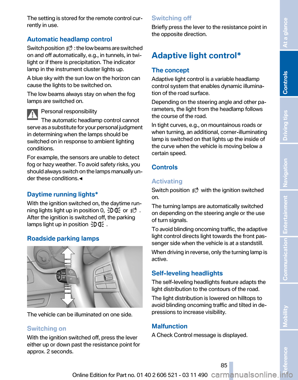
Roadside parking lamps The vehicle can be illuminated on one side.
Switching on
With the ignition switched off, press the lever
either up or down past the resistance point for
approx. 2 seconds. Switching off
Briefly press the lever to the resistance point in
the opposite direction.
Adaptive light control*
The concept
Adaptive light control is a variable headlamp
control system that enables dynamic illumina‐
tion of the road surface.
Depending on the steering angle and other pa‐
rameters, the light from the headlamp follows
the course of the road.
In tight curves, e.g., on mountainous roads or
when turning, an additional, corner-illuminating
lamp is switched on that lights up the inside of
the curve when the vehicle is moving below a
certain speed.
Controls
Activating
Switch position
with the ignition switched
on.
The turning lamps are automatically switched
on depending on the steering angle or the use
of turn signals.
To
avoid blinding oncoming traffic, the adaptive
light control directs light towards the front pas‐
senger side when the vehicle is at a standstill.
When driving in reverse, only the turning lamp is
active.
Self-leveling headlights
The self-leveling headlights feature adapts the
light distribution to the contours of the road.
The light distribution is lowered on hilltops to
avoid blinding oncoming traffic and tilted in de‐
pressions to increase visibility.
Malfunction
A Check Control message is displayed.
Seite 85
85Online Edition for Part no. 01 40 2 606 521 - 03 11 490
Reference Mobility Communication Entertainment Navigation Driving tips
Controls At a glance
Page 89 of 282
▷
Make sure that the front passenger is sitting
correctly, i.e., keeps his or her feet and legs
in the footwell; otherwise, leg injuries can
occur if the front airbag is triggered.
▷ Do not place slip covers, seat cushions or
other objects on the front passenger seat
that are not approved specifically for seats
with integrated side airbags.
▷ Do not hang pieces of clothing, such as jack‐
ets, over the backrests.
▷ Make sure that occupants keep their heads
away from the side airbag; otherwise, inju‐
ries can occur if the airbags are deployed.
▷ Do not remove the airbag restraint system.
▷ Do not remove the steering wheel.
▷ Do not apply adhesive materials to the air‐
bag cover panels, cover them or modify
them in any way.
▷ Never modify either the individual compo‐
nents
or the wiring in the airbag system. This
also applies to steering wheel covers, the
dashboard, and the seats.◀
Even when all instructions are followed closely,
injury from contact with the airbags cannot be
ruled out in certain situations.
The ignition and inflation noise may lead to
short-term
and, in most cases, temporary hear‐
ing impairment in sensitive individuals.
In the case of a malfunction, deactivation
and after triggering of the airbags
Do not touch the individual components imme‐
diately after the system has been triggered; oth‐
erwise, there is the danger of burns.
Only have the airbags checked, repaired or dis‐
mantled and the airbag generator scrapped by
your service center or a workshop that has the
necessary authorization for handling explosives.
Non-professional attempts to service the sys‐
tem could lead to failure in an emergency or un‐
desired triggering of the airbag, either of which
could result in injury.◀
Warnings and information on the airbags are
also found on the sun visors. Functional readiness of the airbag
system
When
the ignition is switch on, the warn‐
ing lamp in the instrument cluster lights
up briefly and thereby indicates the op‐
erational readiness of the entire airbag system
and the belt tensioner.
Airbag system malfunctioning
▷ In radio ready state, the warning lamp does
not come on.
▷ The warning lamp lights up continuously.
When there is a malfunction, have the air‐
bag system checked immediately
When there is a malfunction, have the airbag
system checked immediately; otherwise, there
is
a risk that the system does not function as ex‐
pected in the event of an accident despite cor‐
responding severity of the accident.◀
Automatic deactivation of the front
passenger airbags
The system determines whether the front pas‐
senger seat is occupied by measuring the re‐
sistance of the human body.
The front, knee, and side airbag on the front
passenger side are activated or deactivated ac‐
cordingly.
Leave feet in the footwell
Make sure that the front passenger keeps
his or her feet in the footwell; otherwise, the front
passenger airbags may not function properly.◀
Child restraint fixing system in the front
passenger seat
Before transporting a child on the front passen‐
ger seat, see the safety notes and instructions
under Children on the front passenger seat.◀
Malfunction of the automatic
deactivation system
When transporting older children and adults, the
front passenger airbags may be deactivated in
certain sitting positions. In this case, the indica‐ Seite 89
89Online Edition for Part no. 01 40 2 606 521 - 03 11 490
Reference Mobility Communication Entertainment Navigation Driving tips
Controls At a glance
Page 91 of 282
Rollover protection system
The concept
The
rollover protection system is activated dur‐
ing an accident or a critical driving situation,
when there is extreme tilt with respect to the
longitudinal axis or when there is loss of ground
contact. The safety frames located behind the
rear headrests extend within fractions of a sec‐
ond.
In addition to the rollover bracket integrated in
the front windshield frame, the rollover protec‐
tion system guarantees the required head clear‐
ance of all vehicle occupants.
Maintaining movement space
Always keep the movement space of the
rollover protection system clear. Otherwise,
there may be damage or injuries when the roll‐
over protection system is triggered.◀
In less severe accidents, the secured safety belt
and, depending on the severity of the accident,
the belt tensioner and airbag restraint system
provide protection.
Triggered rollover protection system
After deployment or damage
After deployment of the rollover protec‐
tion system or in the event of damage, have the
system checked and replaced.
Have this work performed only by your service
center; otherwise, it cannot be ensured that this
safety feature will function properly.◀
Do not move convertible top
When the rollover protection system is ex‐
tended, do not move the convertible top. Oth‐
erwise, damages or injuries may result.◀
If the rollover protection system was not placed
under any stress after an automatic triggering, it
can be pushed back by hand, e.g. to close the
convertible top. Three people are necessary for
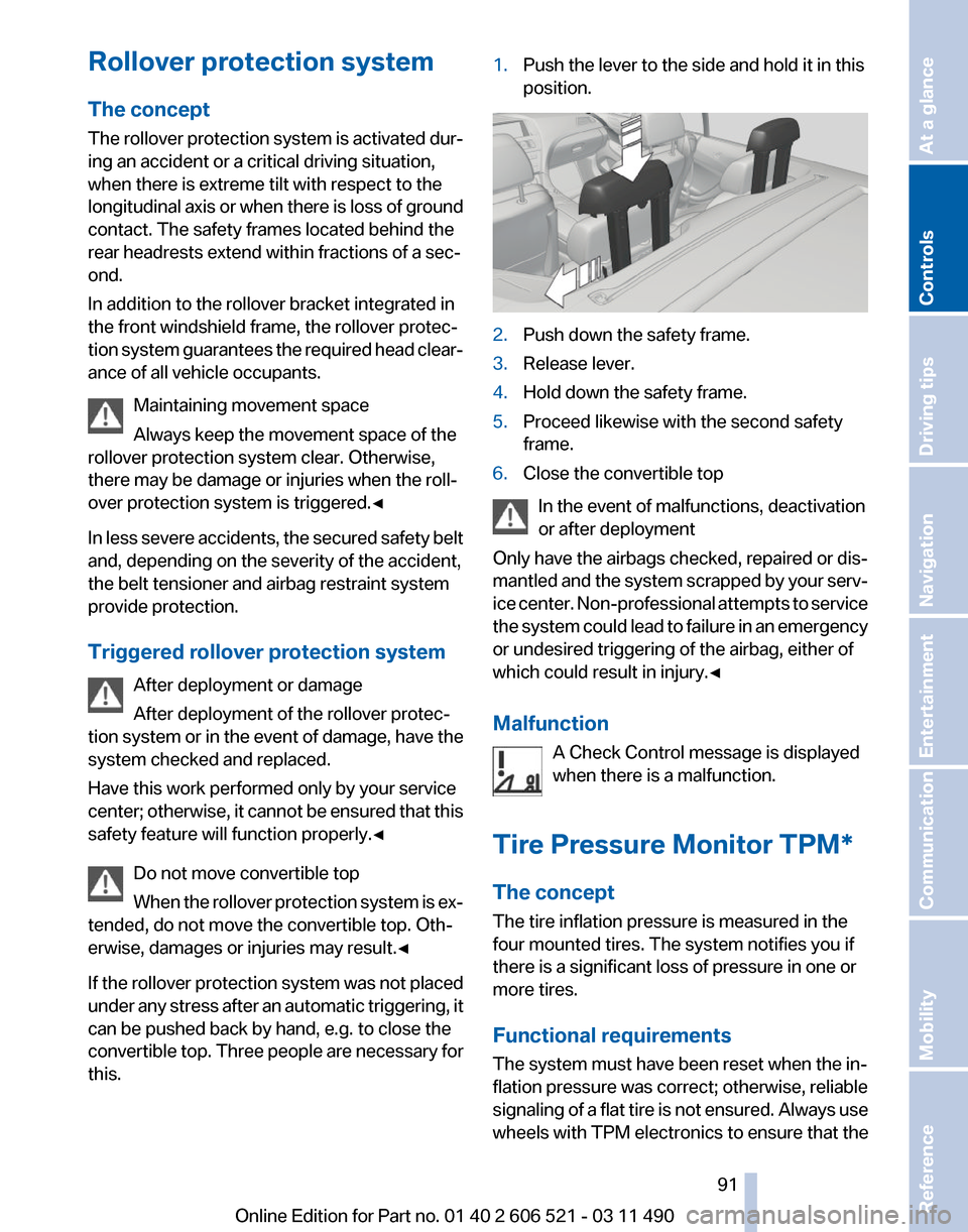
this. 1.
Push the lever to the side and hold it in this
position. 2.
Push down the safety frame.
3. Release lever.
4. Hold down the safety frame.
5. Proceed likewise with the second safety
frame.
6. Close the convertible top
In the event of malfunctions, deactivation
or after deployment
Only have the airbags checked, repaired or dis‐
mantled
and the system scrapped by your serv‐
ice center. Non-professional attempts to service
the system could lead to failure in an emergency
or undesired triggering of the airbag, either of
which could result in injury.◀
Malfunction
A Check Control message is displayed
when there is a malfunction.
Tire Pressure Monitor TPM*
The concept
The tire inflation pressure is measured in the
four mounted tires. The system notifies you if
there is a significant loss of pressure in one or
more tires.
Functional requirements
The system must have been reset when the in‐
flation pressure was correct; otherwise, reliable
signaling of a flat tire is not ensured. Always use
wheels with TPM electronics to ensure that the Seite 91
91Online Edition for Part no. 01 40 2 606 521 - 03 11 490
Reference Mobility Communication Entertainment Navigation Driving tips
Controls At a glance
Page 93 of 282
4.
Start the engine - do not drive away.
5. Reset the tire pressure using "Reset".
6. Drive away.
The tires are shown in gray and "Resetting
TPM..." is displayed.
After
driving for a few minutes, the set tire infla‐
tion pressures are applied as set values. The re‐
setting process is completed automatically dur‐
ing driving. The tires are shown in green and
"TPM active" is shown on the Control Display.
The trip can be interrupted at any time. If you
drive away again, the process resumes auto‐
matically.
If a flat tire is detected during a reset, all tires are
displayed in yellow.
Low tire pressure message
The yellow warning lamp lights up. A
Check Control message is displayed.
▷There is a flat tire or a major loss in
tire inflation pressure.
▷ The system was not reset after a wheel
change and thus warns based on the infla‐
tion pressures initialized last.
1. Reduce your speed and stop cautiously.
Avoid sudden braking and steering maneu‐
vers.
2. Check whether the vehicle is fitted with reg‐
ular tires* or run-flat tires*.
Run-flat
tires, refer to page 234, are labeled
with a circular symbol containing the letters
RSC marked on the tire sidewall.
When a low inflation pressure is indicated, DSC
Dynamic
Stability Control is switched on if nec‐
essary.
Actions in the event of a flat tire
Normal tires*
1. Identify the damaged tire.
Do this by checking the air pressure in all
four tires.
If the tire inflation pressure in all four tires is
correct, the Tire Pressure Monitor may not have been initialized. In this case, initialize
the system.
If an identification is not possible, please
contact the service center.
2. Rectify the flat tire.
Use
of tire sealant, e.g., the Mobility System,
may damage the TPM wheel electronics. In
this case, have the electronics checked at
the next opportunity and have them re‐
placed if necessary.
Run-flat tires*
You
can continue driving with a damaged tire at
speeds up to 50 mph/80 km/h.
Do not continue driving without run-flat
tires
Do not continue driving if the vehicle is not
equipped with run-flat tires; continued driving
may result in serious accidents.◀
Continued driving with a flat tire
If continuing to drive with a damaged tire:
1. Avoid sudden braking and steering maneu‐
vers.
2. Do not exceed a speed of 50 mph/80 km/h.
3. Check the air pressure in all four tires at the
next opportunity.
If the tire inflation pressure in all four tires is
correct, the Flat Tire Monitor may not have
been initialized. In this case, initialize the
system.
If the tire inflation pressure in all four tires is
correct, the Tire Pressure Monitor may not
have been initialized. In this case, initialize
the system.
Possible driving distance with complete loss of
tire inflation pressure:
The possible driving distance after a loss of tire
inflation pressure depends on the cargo load
and the driving style and conditions.
For a vehicle containing an average load, the
possible driving distance is approx. 50 miles/
80 km. Seite 93
93Online Edition for Part no. 01 40 2 606 521 - 03 11 490
Reference Mobility Communication Entertainment Navigation Driving tips
Controls At a glance
Page 95 of 282
main continuously illuminated. This sequence
will
continue upon subsequent vehicle start-ups
as long as the malfunction exists. When the mal‐
function indicator is illuminated, the system may
not be able to detect or signal low tire pressure
as intended. TPMS malfunctions may occur for
a variety of reasons, including the installation of
replacement or alternate tires or wheels on the
vehicle that prevent the TPMS from functioning
properly. Always check the TPMS malfunction
telltale after replacing one or more tires or
wheels on your vehicle to ensure that the re‐
placement or alternate tires and wheels allow
the TPMS to continue to function properly.
FTM Flat Tire Monitor*
The concept
The system does not measure the actual infla‐
tion pressure in the tires.
It detects a pressure loss in a tire by comparing
the rotational speeds of the individual wheels
while moving.
In the event of a pressure loss, the diameter and
therefore the rotational speed of the corre‐
sponding wheel change. This is detected and
reported as a flat tire.
Functional requirements
The system must have been initialized when the
tire inflation pressure was correct; otherwise,
reliable signaling of a flat tire is not ensured. In‐
itialize the system after each correction of the
tire inflation pressure and after every tire or
wheel change.
System limits
Sudden tire damage
Sudden serious tire damage caused by
external influences cannot be indicated in ad‐
vance.◀
A natural, even pressure loss in all four tires can‐
not be detected. Therefore, check the tire infla‐
tion pressure regularly. The system could be delayed or malfunction in
the following situations:
▷
When the system has not been initialized.
▷ When driving on a snowy or slippery road
surface.
▷ Sporty driving style: slip in the drive wheels,
high lateral acceleration.
▷ When driving with snow chains*.
Status display
The current status of the Flat Tire Monitor can
be displayed on the Control Display, e.g.,
whether or not the FTM is active.
1. "Vehicle Info"
2. "Vehicle status"
3. "Flat Tire Monitor"
The status is displayed.
Initialization
The
initialization process adopts the set inflation
tire pressures as reference values for the detec‐
tion of a flat tire. Initialization is started by con‐
firming the inflation pressures.
Do not initialize the system when driving with
snow chains*.
1. "Vehicle Info"
2. "Vehicle status"
3. "Reset"
4. Start the engine - do not drive away.
5. Start the initialization with "Reset".
6. Drive away.
The initialization is completed while driving,
which can be interrupted at any time.
The initialization automatically continues when
driving resumes.
Indication of a flat tire The yellow warning lamp lights up. A
Check Control message is displayed.
There is a flat tire or a major loss in tire
inflation pressure. Seite 95
95Online Edition for Part no. 01 40 2 606 521 - 03 11 490
Reference Mobility Communication Entertainment Navigation Driving tips
Controls At a glance
Page 97 of 282
Lane departure warning*
The concept
This system issues a warning at speeds above
approx. 40 mph/65 km/h if the vehicle is about
to leave the lane on roads with lane markings.
The steering wheel begins vibrating gently.
The system does not provide a warning if the
turn signal is set before leaving the lane.
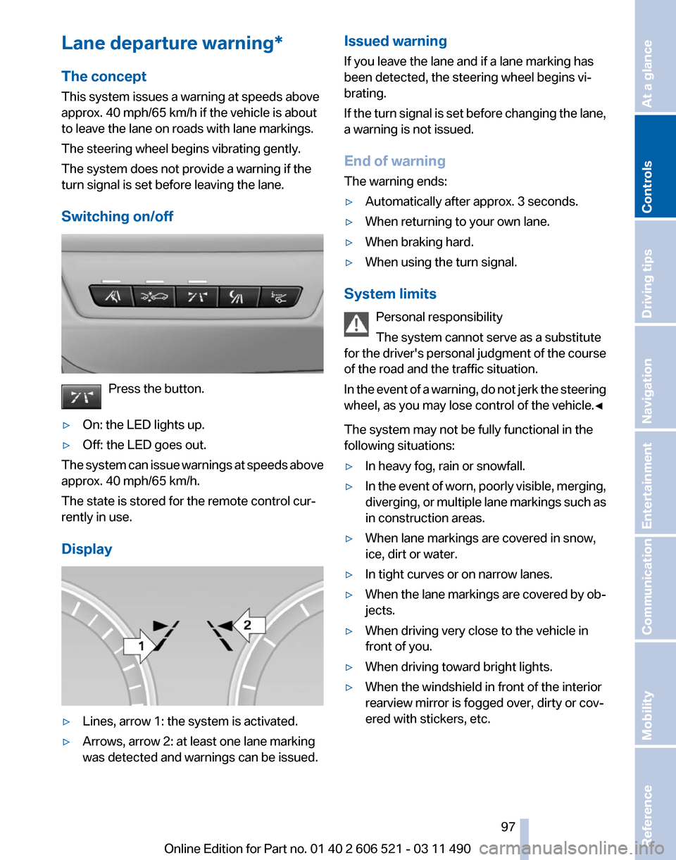
Switching on/off
Press the button.
▷ On: the LED lights up.
▷ Off: the LED goes out.
The system can issue warnings at speeds above
approx. 40 mph/65 km/h.
The state is stored for the remote control cur‐
rently in use.
Display ▷
Lines, arrow 1: the system is activated.
▷ Arrows, arrow 2: at least one lane marking
was detected and warnings can be issued. Issued warning
If you leave the lane and if a lane marking has
been detected, the steering wheel begins vi‐
brating.
If
the turn signal is set before changing the lane,
a warning is not issued.
End of warning
The warning ends:
▷ Automatically after approx. 3 seconds.
▷ When returning to your own lane.
▷ When braking hard.
▷ When using the turn signal.
System limits Personal responsibility
The system cannot serve as a substitute
for
the driver's personal judgment of the course
of the road and the traffic situation.
In the event of a warning, do not jerk the steering
wheel, as you may lose control of the vehicle.◀
The system may not be fully functional in the
following situations:
▷ In heavy fog, rain or snowfall.
▷ In the event of worn, poorly visible, merging,
diverging,
or multiple lane markings such as
in construction areas.
▷ When lane markings are covered in snow,
ice, dirt or water.
▷ In tight curves or on narrow lanes.
▷ When the lane markings are covered by ob‐
jects.
▷ When driving very close to the vehicle in
front of you.
▷ When driving toward bright lights.
▷ When the windshield in front of the interior
rearview mirror is fogged over, dirty or cov‐
ered with stickers, etc. Seite 97
97Online Edition for Part no. 01 40 2 606 521 - 03 11 490
Reference Mobility Communication Entertainment Navigation Driving tips
Controls At a glance
Page 99 of 282
Warning
If the turn signal is set while a vehicle is in the
critical zone, the steering wheel vibrates briefly
and the lamp in the mirror housing flashes
brightly.
The warning stops when the turn signal is
switched
off, or the other vehicle leaves the crit‐
ical zone.
System limits
Personal responsibility
The system cannot serve as a substitute
for the driver's personal judgment of the traffic
situation.
In the event of a warning, do not jerk the steering
wheel, as you may lose control over the vehi‐
cle.◀
The system may not be fully functional in the
following situations:
▷ When a vehicle is approaching at a speed
much faster than your own.
▷ In heavy fog, rain or snowfall.
▷ In tight curves or on narrow lanes.
Malfunctions
Steering wheel vibration
Frequent
activation of the steering wheel vibra‐
tion causes the system to overheat.
This causes Active Blind Spot Detection to be‐
come deactivated.
Let the system cool and reactivate it by pressing
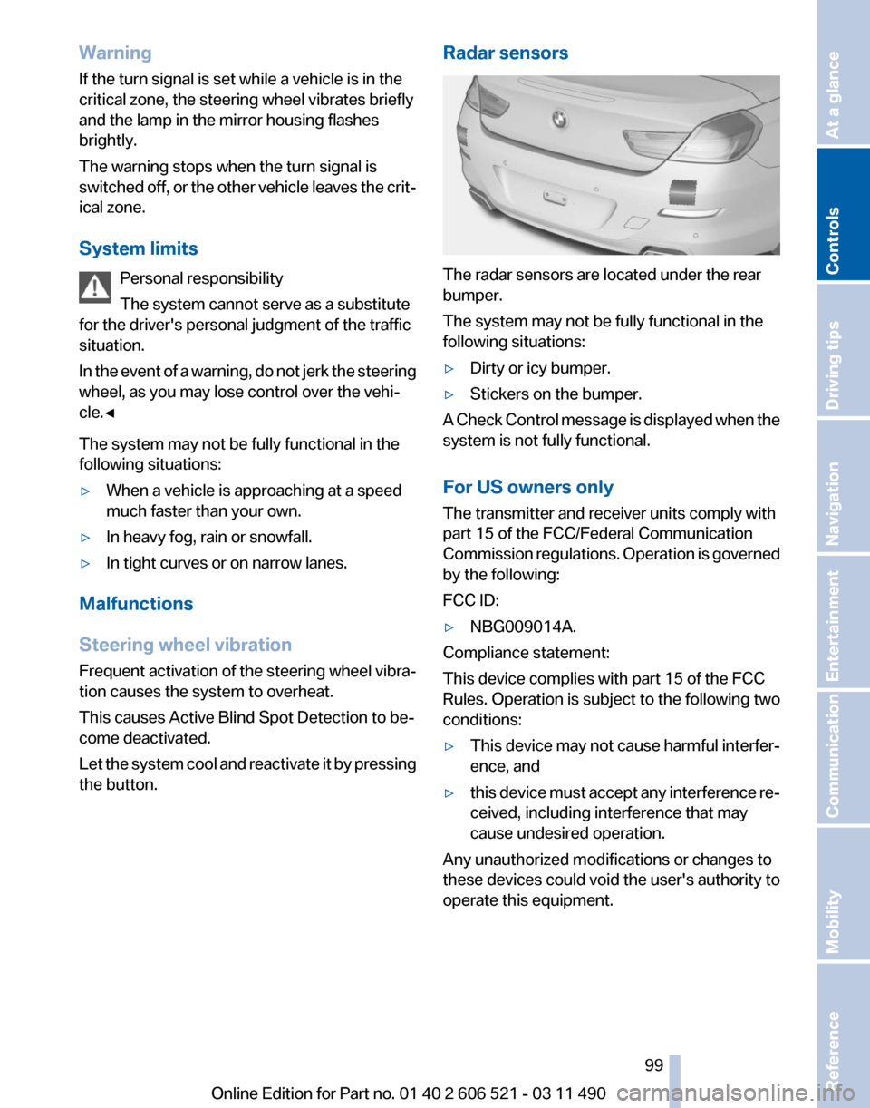
the button. Radar sensors
The radar sensors are located under the rear
bumper.
The system may not be fully functional in the
following situations:
▷
Dirty or icy bumper.
▷ Stickers on the bumper.
A Check Control message is displayed when the
system is not fully functional.
For US owners only
The transmitter and receiver units comply with
part 15 of the FCC/Federal Communication
Commission
regulations. Operation is governed
by the following:
FCC ID:
▷ NBG009014A.
Compliance statement:
This device complies with part 15 of the FCC
Rules. Operation is subject to the following two
conditions:
▷ This device may not cause harmful interfer‐
ence, and
▷ this device must accept any interference re‐
ceived, including interference that may
cause undesired operation.
Any unauthorized modifications or changes to
these devices could void the user's authority to
operate this equipment.
Seite 99
99Online Edition for Part no. 01 40 2 606 521 - 03 11 490
Reference Mobility Communication Entertainment Navigation Driving tips
Controls At a glance
Page 101 of 282
Driving stability control systems
Antilock Brake System ABS
ABS
prevents locking of the wheels during brak‐
ing.
The vehicle remains steerable even during full
brake applications, thus increasing active
safety.
ABS is operational every time you start the en‐
gine.
Brake assistant
When you apply the brakes rapidly, this system
automatically produces the maximum braking
force boost. It thus helps to achieve the shortest
possible braking distance during full braking.
This system utilizes all of the benefits provided
by ABS.
Do not reduce the pressure on the brake pedal
for the duration of the full braking.
Drive-off assistant
This system supports driving away on gradients.
The parking brake is not required.
1. Hold the vehicle in place with the foot brake.
2. Release the foot brake and drive away with‐
out delay.
After the foot brake is released, the vehicle is
held in place for approx. 2 seconds.
Depending on the vehicle load, the vehicle may
roll back slightly.
Driving off without delay
After
releasing the foot brake, start driving
without delay, since the drive-off assistant will
not hold the vehicle in place for more than ap‐
prox. 2 seconds and the vehicle will begin rolling
back.◀ DSC Dynamic Stability
Control
The concept
DSC
prevents traction loss in the driving wheels
when driving away and accelerating.
DSC also recognizes unstable vehicle condi‐
tions, such as fishtailing or nose-diving. Subject
to physical limits, DSC helps to keep the vehicle
on a steady course by reducing engine speed
and by applying brakes at individual wheels.
Adjust your driving style to the situation
An appropriate driving style is always the
responsibility of the driver.
The laws of physics cannot be repealed, even
with DSC.
Therefore, do not reduce the additional safety
margin by driving in a risky manner.◀
Indicator/warning lamps
The indicator lamp flashes: DSC con‐
trols the drive forces and brake forces.
The indicator lamp lights up: DSC has
failed.
DTC Dynamic Traction
Control
The concept
The DTC system is a version of the DSC in which
forward momentum is optimized.
The system ensures maximum forward momen‐
tum on special road conditions, e.g., unplowed
snowy roads, but driving stability is limited.
It is therefore necessary to drive with appropri‐
ate caution.
You may find it useful to briefly activate DTC un‐
der the following special circumstances: Seite 101
101Online Edition for Part no. 01 40 2 606 521 - 03 11 490
Reference Mobility Communication Entertainment Navigation Driving tips
Controls At a glance
Page 103 of 282
The rear wheels are turned to the same angle as
the front wheels.
In
critical situations, Integral Active Steering can
specifically steer the front and rear wheels to
stabilize the vehicle before the driver intervenes,
e.g., when braking where road conditions differ
on the left and right sides of the vehicle.
Initializing
In rare cases, it may become necessary to initi‐
alize the Integral Active Steering.
The warning lamp lights up. A Check
Control message is displayed.
1. With the engine running, turn the steering
wheel
all the way to the left and right several
times in a uniform manner until the warning
lamp disappears.
2. Have the system checked if the warning
lamp
does not go out after moving the steer‐
ing wheel approx. 6 times or if the steering
wheel is at an angle.
Using snow chains
Ensure
that the rear axle steering is deactivated
when using snow chains, refer to page 235.
Programs
The system offers two different programs.
The programs can be selected via Dynamic Driv‐
ing Control, refer to page 103.
SPORT
Consistently sporty tuning of the Integral Active
Steering for greater driving agility.
NORMAL
Balanced tuning of the Integral Active Steering
for optimal traveling comfort.
Malfunction
In the event of a malfunction, the steering wheel
must be turned further, while the vehicle re‐
sponds more sensitively to steering wheel
movements in the higher speed range. The stability-enhancing intervention may be de‐
activated.
Proceed cautiously and drive defensively.
Have the system checked.
Dynamic Driving Control*
The concept
Dynamic Driving Control can be used to adjust
the
driving dynamics of the vehicle. Several pro‐
grams are available for this purpose; they can be
activated using the two Dynamic Driving Control
buttons.
Operating the programs Press the button Program
DSC OFF
TRACTION
SPORT+
SPORT
NORMAL
COMFORT*
For Adaptive Drive* or Dynamic Damper Con‐
trol*, the lower button is labeled with COM‐
FORT.
Automatic program change
The
system automatically switches to NORMAL
in the following situations:
▷ Failure of Integral Active Steering*.
▷ Failure of Dynamic Damping Control*.
▷ The vehicle has a flat tire.
DSC OFF
Driving stability is limited during acceleration
and when driving in bends.
Stabilizing interventions by the
Integral Active
Steering* system are only performed by the rear
axle steering.
Seite 103
103Online Edition for Part no. 01 40 2 606 521 - 03 11 490
Reference Mobility Communication Entertainment Navigation Driving tips
Controls At a glance