Rear BMW 7 SERIES 2016 G11 Owner's Guide
[x] Cancel search | Manufacturer: BMW, Model Year: 2016, Model line: 7 SERIES, Model: BMW 7 SERIES 2016 G11Pages: 314, PDF Size: 7.9 MB
Page 90 of 314
General information
The following settings are applied to the seat
automatically on system activation:▷The front passenger's seat moves forward
and adjusts the height if necessary.▷Backrest and head restraint of the front
passenger seat are inclined forward.▷The tilt of the screen in the rear is adjusted
to the rest incline of the passenger's seat.▷The head restraint on the backrest of the
front passenger seat folds out.▷The backrest of the rear seat inclines to the
rear.
The adjusted end position can be manually ad‐
justed, refer to page 78, and stored using the
Memory function, refer to page 87, if needed.
Information WARNING
If the Captain’s chair is activated, the
view on the right exterior mirror can be ob‐
structed. There is risk of an accident. Adjust
the front passenger seat such that the view on
the exterior mirror is not obstructed.◀
Overview
Captain’s chair
Switching on Press button.
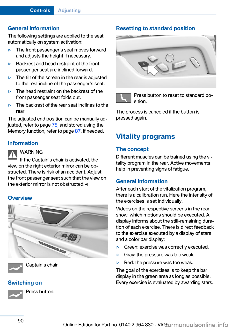
Resetting to standard position
Press button to reset to standard po‐
sition.
The process is canceled if the button is
pressed again.
Vitality programs The concept
Different muscles can be trained using the vi‐
tality program in the rear. Active movements
help in preventing signs of fatigue.
General information After each start of the vitalization program,
there is a calibration run. Here the intensity of
the exercises is set individually.
Videos on the respective screens in the rear
show, which motions should be executed. A
display informs about the still-remaining dura‐
tion of each exercise. There is direct feedback
to the exercise executed by a display of stars
and a color bar display:
▷Green: exercise was correctly executed.▷Gray: the pressure was too weak.▷Red: the pressure was too weak.
The goal of the exercises is to keep the bar
display in the green area as long as possible.
Every exercise is evaluated by awarding stars.
Seite 90ControlsAdjusting90
Online Edition for Part no. 0140 2 964 330 - VI/15
Page 91 of 314
Switching onOn the screens in the rear:1."My Vehicle"2."Seat comfort"3."BMW Vitality Program"
Switch off
On the screens in the rear:
1.Press left arrow button on the remote con‐
trol in the rear.2."Stop"
BMW Touch Command
The vitality program can also be operated us‐
ing BMW Touch Command.
Seat and armrest heating
General information The system heats seats and armrests as
needed. Seat heating can also be used without
armrest heating.
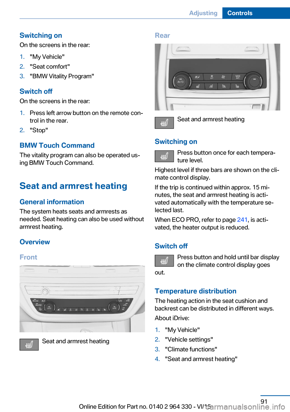
Overview
Front
Seat and armrest heating
Rear
Seat and armrest heating
Switching on Press button once for each tempera‐
ture level.
Highest level if three bars are shown on the cli‐
mate control display.
If the trip is continued within approx. 15 mi‐
nutes, the seat and armrest heating is acti‐
vated automatically with the temperature se‐
lected last.
When ECO PRO, refer to page 241, is acti‐
vated, the heater output is reduced.
Switch off Press button and hold until bar display
on the climate control display goes
out.
Temperature distribution The heating action in the seat cushion and
backrest can be distributed in different ways.
About iDrive:
1."My Vehicle"2."Vehicle settings"3."Climate functions"4."Seat and armrest heating"Seite 91AdjustingControls91
Online Edition for Part no. 0140 2 964 330 - VI/15
Page 92 of 314
5.Select desired seat.6.Pres the controller and turn to set the tem‐
perature distribution.
Switching armrest heating on/off
About iDrive:
1."My Vehicle"2."Vehicle settings"3."Climate functions"4."Seat and armrest heating"5.Select desired seat.6."Heat up armrest together with seat"
Active seat ventilation
The concept
The seat cushion and backrest surfaces are
cooled by means of integrated fans.
The ventilation cools the seat, e. g., if the vehi‐
cle interior is overheated or for continuous
cooling at high temperatures.
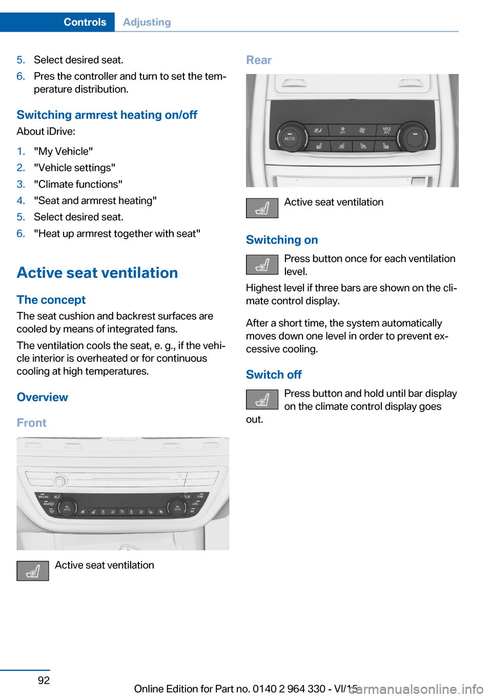
Overview
Front
Active seat ventilation
Rear
Active seat ventilation
Switching on Press button once for each ventilation
level.
Highest level if three bars are shown on the cli‐
mate control display.
After a short time, the system automatically
moves down one level in order to prevent ex‐
cessive cooling.
Switch off Press button and hold until bar display
on the climate control display goes
out.
Seite 92ControlsAdjusting92
Online Edition for Part no. 0140 2 964 330 - VI/15
Page 93 of 314
Transporting children safelyVehicle features and optionsThis chapter describes all standard, country-
specific and optional features offered with the
series. It also describes features that are not
necessarily available in your car, e. g., due tothe selected options or country versions. This
also applies to safety-related functions and
systems. The respectively applicable country
provisions must be observed when using the
respective features and systems.
The right place for children
Information
WARNING
Unattended children or animals can
move the vehicle and endanger themselves
and traffic, e.g. with the following actions:▷Pressing the Start/Stop button.▷Releasing the parking brake.▷Opening and closing of doors or windows.▷Shifting the selector lever into neutral.▷Using vehicle equipment.
There is risk of accidents or injuries. Do not
leave children or animals unattended in the ve‐
hicle. Carry remote control along when exiting
and lock the vehicle.◀
Children should always be in the rear WARNING
Persons shorter than 5 ft, 150 cm cannot
correctly fasten the safety belt without suitable
additional restraint systems. The protective ef‐
fect of the safety belts can be limited or lost
when safety belts are fastened incorrectly. An
incorrectly fastened safety belt can cause ad‐
ditional injuries, e.g. in the event of an accident
or during braking and evasive maneuvers.
There is risk of injuries or danger to life. Secure
persons shorter than 5 ft, 150 cm using suita‐
ble restraint systems.◀
Accident research shows that the safest place
for children is in the back seat.
Only transport children younger than 13 years
of age or shorter than 5 ft, 150 cm in the rear in
child restraint systems provided in accordance
with the age, weight and size of the child.
Children 13 years of age or older must wear a
safety belt as soon as a suitable child restraint
system can no longer be used due to their age,
weight and size.
Children on the front passenger seat
Before using a child restraint system on the
front passenger seat, ensure that the front,
knee, and side airbags on the front passenger
side are deactivated. Automatic deactivation of
front-seat passenger airbags, refer to
page 138.
Information WARNING
Active front-seat passenger airbags can
injure a child in a child restraint system when
the airbags are activated. There is risk of inju‐
ries. Make sure that the front-seat passenger
airbags are deactivated and that the PASSEN‐
GER AIRBAG OFF indicator lamp lights up.◀Seite 93Transporting children safelyControls93
Online Edition for Part no. 0140 2 964 330 - VI/15
Page 94 of 314
Installing child restraint
systems
Information
Pay attention to the specifications of the child
restraint system manufacturer when selecting,
installing, and using child restraint systems.
WARNING
The stability of the child restraint system
is limited or compromised with incorrect seat
adjustment or improper installation of the child
seat. There is risk of injuries or danger to life.
Make sure that the child restraint system fits
securely against the backrest. If possible, ad‐
just the backrest tilt for all affected backrests
and correctly adjust the seats. Make sure that
seats and backrests are securely engaged. If
possible, adjust the height of the head re‐
straints or remove them.◀
On the front passenger seat
Deactivating airbags WARNING
Active front-seat passenger airbags can
injure a child in a child restraint system when
the airbags are activated. There is risk of inju‐
ries. Make sure that the front-seat passenger
airbags are deactivated and that the PASSEN‐
GER AIRBAG OFF indicator lamp lights up.◀
After installing a child restraint system in the
front passenger seat, make sure that the front,
knee and side airbags on the front passenger
side are deactivated.
Deactivate the front-seat passenger airbags
automatically, refer to page 138.
Seat position and height Before installing a child restraint system, move
the front passenger seat as far back as possi‐
ble and bring it up to medium height to obtain
the best possible position for the belt and tooffer optimal protection in the event of an acci‐
dent.
If the upper anchorage of the safety belt is lo‐
cated in front of the belt guide of the child seat,
move the passenger seat carefully forward un‐
til the best possible belt guide position is
reached.
Backrest width Adjustable backrest width: before installing a
child restraint system in the front passenger
seat, open the backrest width completely. Do
not change the backrest width again and do
not call up a memory position.
Child seat security
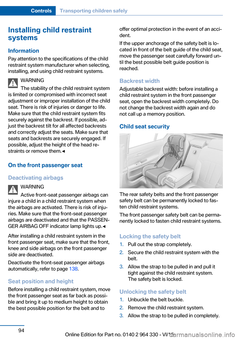
The rear safety belts and the front passenger
safety belt can be permanently locked to fas‐
ten child restraint systems.
The front passenger safety belt can be perma‐
nently locked to fasten child restraint systems.
Locking the safety belt
1.Pull out the strap completely.2.Secure the child restraint system with the
belt.3.Allow the strap to be pulled in and pull it
tight against the child restraint system.
The safety belt is locked.
Unlocking the safety belt
1.Unbuckle the belt buckle.2.Remove the child restraint system.3.Allow the strap to be pulled in completely.Seite 94ControlsTransporting children safely94
Online Edition for Part no. 0140 2 964 330 - VI/15
Page 95 of 314
LATCH child restraint systemLATCH: Lower Anchors and Tether for Chil‐
dren.
Information
Pay attention to the operating and safety infor‐
mation of the child restraint system manufac‐
turer when installing and using LATCH child
restraint fixing system.
Mounts for the lower LATCH anchors
General information
The lower anchors may be used to attach the
CRS to the vehicle seat up to a combined child
and CRS weight of 65 lb/30 kg when the child
is restrained by the internal harnesses.
Information WARNING
If the LATCH child restraint fixing sys‐
tems are not correctly engaged, the protective
effect of the LATCH child restraint fixing sys‐
tem can be limited. There is risk of injuries or
danger to life. Make sure that the lower an‐
chors are securely engaged and that the
LATCH child restraint fixing system fits se‐
curely against the backrest.◀
Position The corresponding symbol shows the
mounts for the lower LATCH anchors.
Seats equipped with lower anchors are
marked with a pair, 2, of LATCH sym‐
bols. It is not recommended to use the
inner lower anchors of standard outer
LATCH positions to fasten a child restraint system on the middle seat. Use the vehicle
seat belt instead for the middle seat.Before installing LATCH child
restraint systems
Pull the belt away from the area of the child re‐
straint system.
Without comfort seats in the rear:
Assembly of LATCH child restraint
systems1.Install child restraint system, see manufac‐
turer's information.2.Ensure that both LATCH anchors are prop‐
erly connected.
With comfort rear seats: Assembly of
LATCH child restraint fixing systems
1.Before mounting, adjust the seats to their
basic position, refer to page 80.2.For better accessibility, tilt the backrest
back slightly.3.Install child restraint system, see manufac‐
turer's information.4.Ensure that both LATCH anchors are prop‐
erly connected.5.After mounting, move the backrest back up
slightly so that the child restraint system
rests lightly against the backrest.
Child restraint fixing system with a
tether strap
Mounting points The respective symbol shows the an‐
chor for the upper retaining strap.
Seats with an upper Top Tether are
marked with this symbol. It can be found on
the rear seat backrest or the rear window shelf.
Seite 95Transporting children safelyControls95
Online Edition for Part no. 0140 2 964 330 - VI/15
Page 96 of 314
InformationCAUTION
The mounting points for the upper re‐
taining straps of child restraint systems are
only provided for these retaining straps. When
other objects are mounted, the anchors can be
damaged. There is risk of property damage.
Only mount child restraint systems to the up‐
per retaining straps.◀
Retaining strap guide WARNING
If the upper retaining strap is incorrectly
used for the child restraint system, the protec‐
tive effect can be reduced. There is risk of inju‐
ries. Make sure that the upper retaining strap is
not guided across sharp edges and without
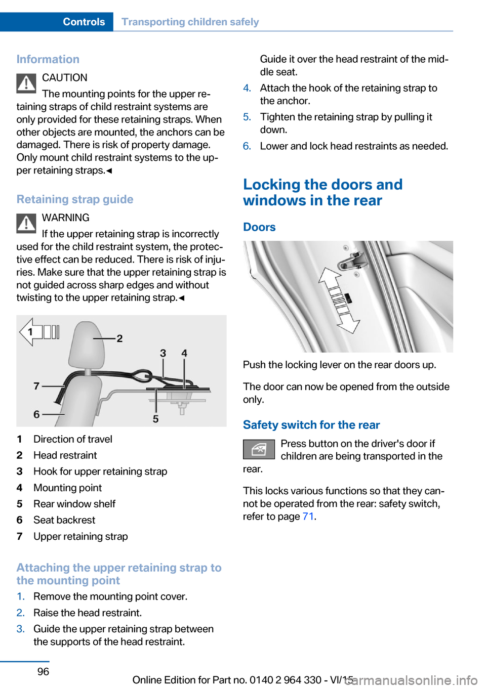
twisting to the upper retaining strap.◀1Direction of travel2Head restraint3Hook for upper retaining strap4Mounting point5Rear window shelf6Seat backrest7Upper retaining strap
Attaching the upper retaining strap to
the mounting point
1.Remove the mounting point cover.2.Raise the head restraint.3.Guide the upper retaining strap between
the supports of the head restraint.Guide it over the head restraint of the mid‐
dle seat.4.Attach the hook of the retaining strap to
the anchor.5.Tighten the retaining strap by pulling it
down.6.Lower and lock head restraints as needed.
Locking the doors and
windows in the rear
Doors
Push the locking lever on the rear doors up.
The door can now be opened from the outside
only.
Safety switch for the rear Press button on the driver's door if
children are being transported in the
rear.
This locks various functions so that they can‐
not be operated from the rear: safety switch,
refer to page 71.
Seite 96ControlsTransporting children safely96
Online Edition for Part no. 0140 2 964 330 - VI/15
Page 104 of 314
Switching on
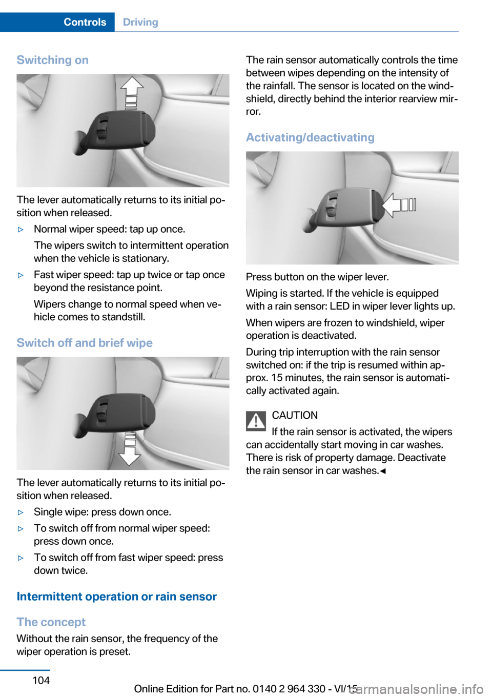
The lever automatically returns to its initial po‐
sition when released.
▷Normal wiper speed: tap up once.
The wipers switch to intermittent operation
when the vehicle is stationary.▷Fast wiper speed: tap up twice or tap once
beyond the resistance point.
Wipers change to normal speed when ve‐
hicle comes to standstill.
Switch off and brief wipe
The lever automatically returns to its initial po‐
sition when released.
▷Single wipe: press down once.▷To switch off from normal wiper speed:
press down once.▷To switch off from fast wiper speed: press
down twice.
Intermittent operation or rain sensor
The concept Without the rain sensor, the frequency of the
wiper operation is preset.
The rain sensor automatically controls the time
between wipes depending on the intensity of the rainfall. The sensor is located on the wind‐
shield, directly behind the interior rearview mir‐
ror.
Activating/deactivating
Press button on the wiper lever.
Wiping is started. If the vehicle is equipped
with a rain sensor: LED in wiper lever lights up.
When wipers are frozen to windshield, wiper
operation is deactivated.
During trip interruption with the rain sensor
switched on: if the trip is resumed within ap‐
prox. 15 minutes, the rain sensor is automati‐
cally activated again.
CAUTION
If the rain sensor is activated, the wipers
can accidentally start moving in car washes.
There is risk of property damage. Deactivate
the rain sensor in car washes.◀
Seite 104ControlsDriving104
Online Edition for Part no. 0140 2 964 330 - VI/15
Page 108 of 314
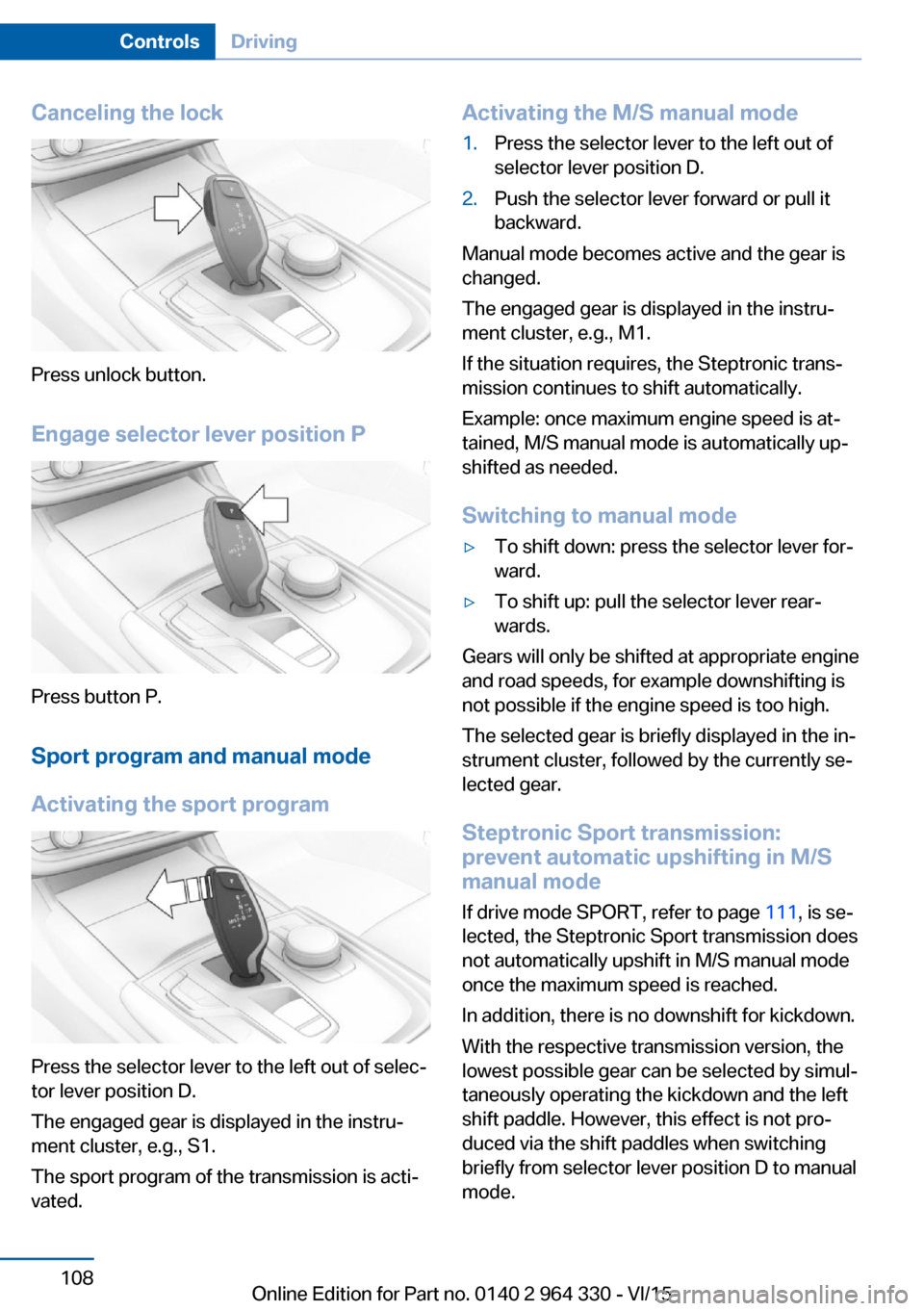
Canceling the lock
Press unlock button.Engage selector lever position P
Press button P.Sport program and manual mode
Activating the sport program
Press the selector lever to the left out of selec‐
tor lever position D.
The engaged gear is displayed in the instru‐
ment cluster, e.g., S1.
The sport program of the transmission is acti‐
vated.
Activating the M/S manual mode1.Press the selector lever to the left out of
selector lever position D.2.Push the selector lever forward or pull it
backward.
Manual mode becomes active and the gear is
changed.
The engaged gear is displayed in the instru‐
ment cluster, e.g., M1.
If the situation requires, the Steptronic trans‐
mission continues to shift automatically.
Example: once maximum engine speed is at‐
tained, M/S manual mode is automatically up‐
shifted as needed.
Switching to manual mode
▷To shift down: press the selector lever for‐
ward.▷To shift up: pull the selector lever rear‐
wards.
Gears will only be shifted at appropriate engine
and road speeds, for example downshifting is
not possible if the engine speed is too high.
The selected gear is briefly displayed in the in‐
strument cluster, followed by the currently se‐
lected gear.
Steptronic Sport transmission:
prevent automatic upshifting in M/S
manual mode
If drive mode SPORT, refer to page 111, is se‐
lected, the Steptronic Sport transmission does
not automatically upshift in M/S manual mode
once the maximum speed is reached.
In addition, there is no downshift for kickdown.
With the respective transmission version, the
lowest possible gear can be selected by simul‐
taneously operating the kickdown and the left
shift paddle. However, this effect is not pro‐
duced via the shift paddles when switching
briefly from selector lever position D to manual
mode.
Seite 108ControlsDriving108
Online Edition for Part no. 0140 2 964 330 - VI/15
Page 120 of 314
Gear shift indicatorThe conceptThe system recommends the most fuel effi‐
cient gear for the current driving situation.
General information
Depending on the vehicle's features and coun‐
try version of the vehicle, the gear shift indica‐
tor is active in the manual mode of the Step‐
tronic transmission.
Suggestions to shift gear up or down are dis‐
played in the instrument cluster.
On vehicles without a gear shift indicator, the
engaged gear is displayed.
DisplaysExampleDescriptionFuel efficient gear is set.Shift into fuel efficient gear.
Speed limit detection
The concept
Speed limit detection
Speed limit detection shows the current maxi‐
mum permitted speed in the instrument clus‐
ter. The camera in the area of the interior rear‐
view mirror detects traffic signs at the edge of
the road as well as variable overhead sign
posts. Traffic signs with extra symbols for wet
road conditions, etc. are also detected and
compared with the vehicle's onboard data,
such as for the rain sensor, and will be dis‐
played depending on the situation. The system
takes into account the information stored in
the navigation system and also displays speed
limits present on routes without signs.
Information WARNING
The system does not relieve from the
personal responsibility to correctly assess visi‐
bility and traffic situation. There is risk of an ac‐
cident. Adjust the driving style to the traffic
conditions. Watch traffic closely and actively
interfere in the respective situations.◀
Overview
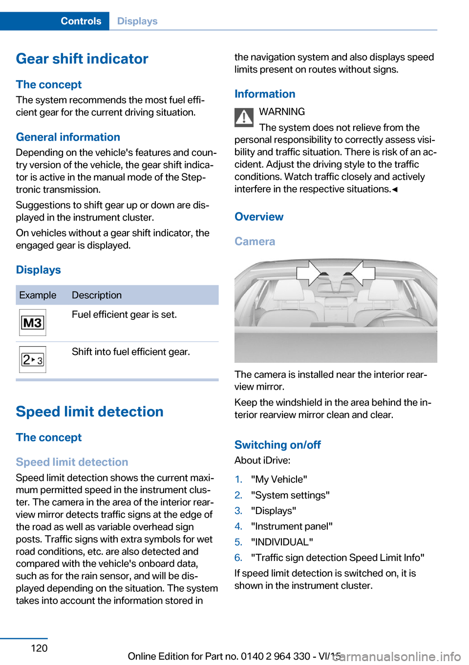
Camera
The camera is installed near the interior rear‐
view mirror.
Keep the windshield in the area behind the in‐
terior rearview mirror clean and clear.
Switching on/offAbout iDrive:
1."My Vehicle"2."System settings"3."Displays"4."Instrument panel"5."INDIVIDUAL"6."Traffic sign detection Speed Limit Info"
If speed limit detection is switched on, it is
shown in the instrument cluster.
Seite 120ControlsDisplays120
Online Edition for Part no. 0140 2 964 330 - VI/15