Dme BMW 740i 2001 E38 M62TU Engine Workshop Manual
[x] Cancel search | Manufacturer: BMW, Model Year: 2001, Model line: 740i, Model: BMW 740i 2001 E38Pages: 37, PDF Size: 3.9 MB
Page 5 of 37
5
BASIC FUNCTION OF BMW VANOS SYSTEMS
All BMW VANOS systems are operated through electric/hydraulic/mechanical control.
Electric Control: The engine control module is responsible for activating a VANOS sole-
noid valve based on DME program mapping. The activation parameters are influenced
by the following input signals:
• Engine speed
• Load (intake air mass)
• Engine temperature
• Camshaft position
• Oil temperature (MS 42.0 only)
Depending on the specific VANOS system, the solenoid valve is one of two types:
• Basic black/white (on/off) solenoid valve. Found on M50 TU and M52 engines.
• Variable position solenoid valve. Found on the M52 TU and M62 TU engines.
Hydraulic Control:The position of the solenoid valve directs the hydraulic flow of engine
oil. The controlled oil flow acts on the mechanical components of VANOS system to
position the camshaft.
Mechanical Control: The mechanical components of all VANOS systems operate under
the same principle. The controlled hydraulic engine oil flow is directed through advance
or retard activation oil ports. Each port exits into a sealed chamber on the opposite sides
of a control piston.
• The control piston on six cylinder engine systems (M50TU, M52 & M52TU) is con-
nected to a separate helical gear cup.
• The control piston on the M62TU VANOS system incorporates the helical gear.
In its default position the oil flow is directed to the rear surface of the piston. This pulls
the helical gear forward and maintains the retarded valve timing position.
When the oil flow is directed to the front surface of the piston, the oil pushesthe helical
gear in the opposite direction which rotates the matched helical gearing connected to the
camshaft.
The angled teeth of the helical gears cause thepushingmovement to be converted into
arotationalmovement. The rotational movement is added to the turning of the
camshaft providing the variable camshaft positioning.
Page 15 of 37
15
DME-ME 7.2 ENGINE MANAGEMENT SYSTEM
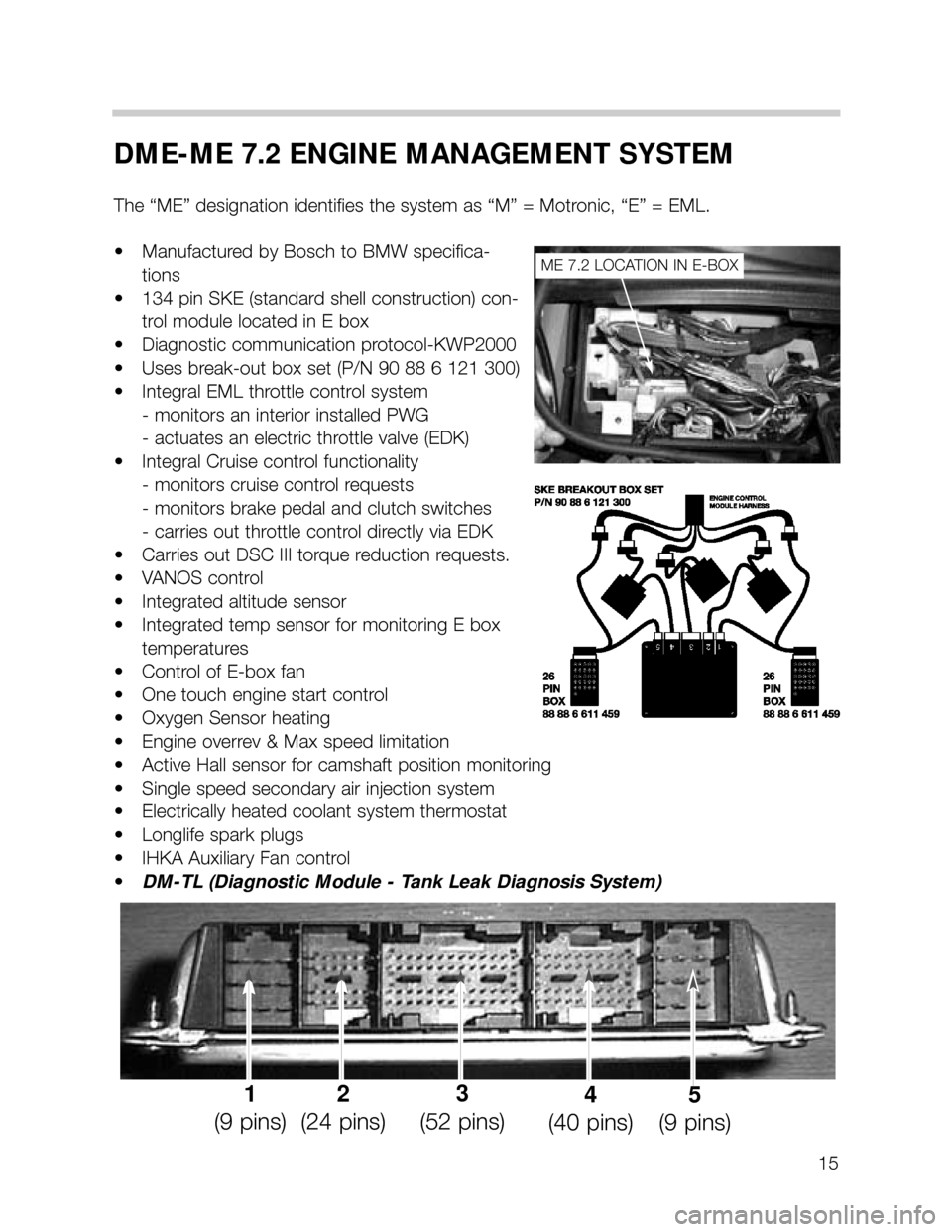
The “ME” designation identifies the system as “M” = Motronic, “E” = EML.
• Manufactured by Bosch to BMW specifica-
tions
• 134 pin SKE (standard shell construction) con-
trol module located in E box
• Diagnostic communication protocol-KWP2000
• Uses break-out box set (P/N 90 88 6 121 300)
• Integral EML throttle control system
- monitors an interior installed PWG
- actuates an electric throttle valve (EDK)
• Integral Cruise control functionality
- monitors cruise control requests
- monitors brake pedal and clutch switches
- carries out throttle control directly via EDK
• Carries out DSC III torque reduction requests.
• VANOS control
• Integrated altitude sensor
• Integrated temp sensor for monitoring E box
temperatures
• Control of E-box fan
• One touch engine start control
• Oxygen Sensor heating
• Engine overrev & Max speed limitation
• Active Hall sensor for camshaft position monitoring
• Single speed secondary air injection system
• Electrically heated coolant system thermostat
• Longlife spark plugs
• IHKA Auxiliary Fan control
•DM-TL (Diagnostic Module - Tank Leak Diagnosis System)
ME 7.2 LOCATION IN E-BOX
1
(9 pins)2
(24 pins)3
(52 pins)4
(40 pins)5
(9 pins)
Page 28 of 37
28
SECONDARY AIR INJECTION
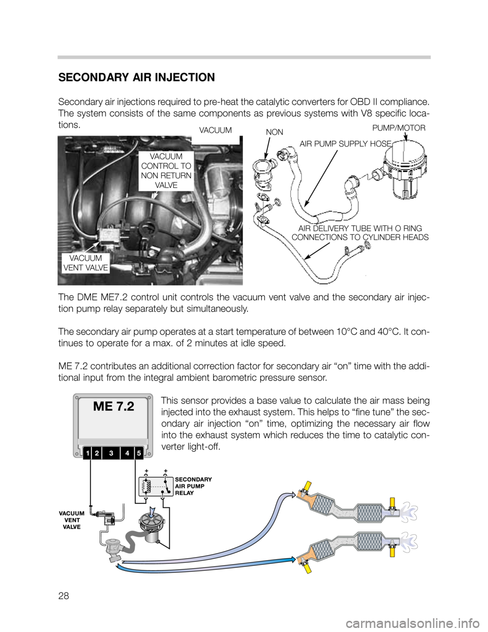
Secondary air injections required to pre-heat the catalytic converters for OBD II compliance.
The system consists of the same components as previous systems with V8 specific loca-
tions.
The DME ME7.2 control unit controls the vacuum vent valve and the secondary air injec-
tion pump relay separately but simultaneously.
The secondary air pump operates at a start temperature of between 10°C and 40°C. It con-
tinues to operate for a max. of 2 minutes at idle speed.
ME 7.2 contributes an additional correction factor for secondary air “on” time with the addi-
tional input from the integral ambient barometric pressure sensor.
This sensor provides a base value to calculate the air mass being
injected into the exhaust system. This helps to “fine tune” the sec-
ondary air injection “on” time, optimizing the necessary air flow
into the exhaust system which reduces the time to catalytic con-
verter light-off.
VACUUM
VACUUM
VENT VALVENONPUMP/MOTOR
AIR PUMP SUPPLY HOSE
AIR DELIVERY TUBE WITH O RING
CONNECTIONS TO CYLINDER HEADS
VACUUM
CONTROL TO
NON RETURN
VA LV E
Page 29 of 37
29
AUXILIARY FAN CONTROL
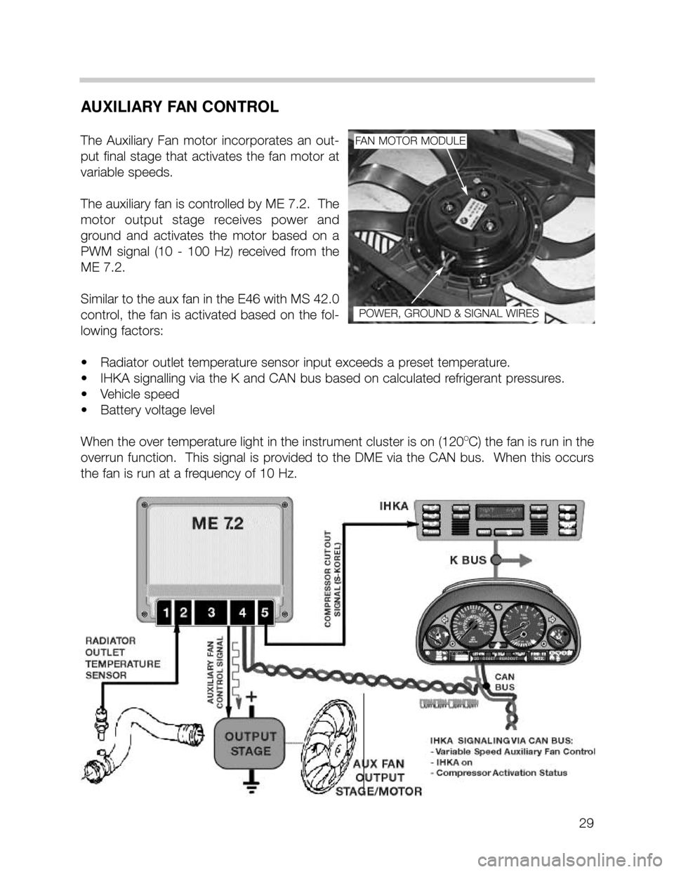
The Auxiliary Fan motor incorporates an out-
put final stage that activates the fan motor at
variable speeds.
The auxiliary fan is controlled by ME 7.2. The
motor output stage receives power and
ground and activates the motor based on a
PWM signal (10 - 100 Hz) received from the
ME 7.2.
Similar to the aux fan in the E46 with MS 42.0
control, the fan is activated based on the fol-
lowing factors:
• Radiator outlet temperature sensor input exceeds a preset temperature.
• IHKA signalling via the K and CAN bus based on calculated refrigerant pressures.
• Vehicle speed
• Battery voltage level
When the over temperature light in the instrument cluster is on (120
OC) the fan is run in the
overrun function. This signal is provided to the DME via the CAN bus. When this occurs
the fan is run at a frequency of 10 Hz.
FAN MOTOR MODULE
POWER, GROUND & SIGNAL WIRES
Page 32 of 37
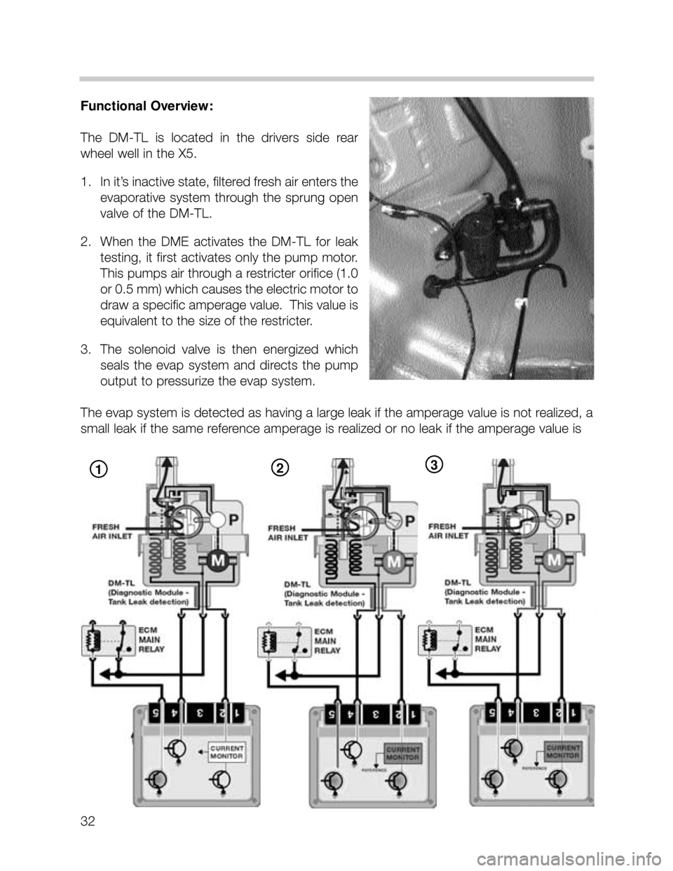
Functional Overview:
The DM-TL is located in the drivers side rear
wheel well in the X5.
1. In it’s inactive state, filtered fresh air enters the
evaporative system through the sprung open
valve of the DM-TL.
2. When the DME activates the DM-TL for leak
testing, it first activates only the pump motor.
This pumps air through a restricter orifice (1.0
or 0.5 mm) which causes the electric motor to
draw a specific amperage value. This value is
equivalent to the size of the restricter.
3. The solenoid valve is then energized which
seals the evap system and directs the pump
output to pressurize the evap system.
The evap system is detected as having a large leak if the amperage value is not realized, a
small leak if the same reference amperage is realized or no leak if the amperage value is
32
123
Page 34 of 37

LEAK DIAGNOSIS TEST PRECONDITIONS
The DME only initiates a leak diagnosis test every second time the criteria are met. The cri-
teria is as follows:
• Engine OFF with ignition switched OFF.
• Engine Control Module still in active state or what is known as “follow up mode” (Main
Relay energized, control module and DME components online for extended period after
key off).
• Prior to Engine/Ignition switch OFF condition, vehicle must have been driven for a min-
imum of 20 minutes.
• Prior to minimum 20 minute drive, the vehicle must have been OFF for a minimum of 5
hours.
• Fuel Tank Capacity must be between 15 and 85%(safe approximation between 1/4 -
3/4 of a tank).
• Ambient Air Temperature between -7
OC & 35OC(20OF & 95OF )
• Altitude < 2500m(8,202 feet).
• Battery Voltage between 11.5 and 14.5 Volts
When these criteria are satisfied every second time, the ECM will start the Fuel System Leak
Diagnosis Test. The test will typically be carried out once a day i.e. once after driving to
work in the morning, when driving home in the evening, the criteria are once again met but
the test is not initiated. The following morning, the test will run again.
34