sensor BMW 740IL 1996 E38 Level Control System Manual
[x] Cancel search | Manufacturer: BMW, Model Year: 1996, Model line: 740IL, Model: BMW 740IL 1996 E38Pages: 57, PDF Size: 1.89 MB
Page 31 of 57
31
Level Control Systems
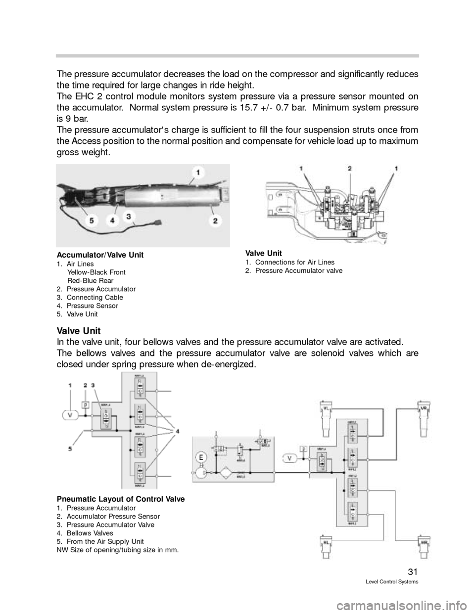
The pressure accumulator decreases the load on the compressor and significantly reduces
the time required for large changes in ride height.
The EHC 2 control module monitors system pressure via a pressure sensor mounted on
the accumulator. Normal system pressure is 15.7 +/- 0.7 bar. Minimum system pressure
is 9 bar.
The pressure accumulator's charge is sufficient to fill the four suspension struts once from
the Access position to the normal position and compensate for vehicle load up to maximum
gross weight.
Valve Unit
In the valve unit, four bellows valves and the pressure accumulator valve are activated.
The bellows valves and the pressure accumulator valve are solenoid valves which are
closed under spring pressure when de-energized.
Accumulator/Valve Unit
1. Air Lines
Yellow-Black Front
Red-Blue Rear
2. Pressure Accumulator
3. Connecting Cable
4. Pressure Sensor
5. Valve Unit
Valve Unit
1. Connections for Air Lines
2. Pressure Accumulator valve
Pneumatic Layout of Control Valve
1. Pressure Accumulator
2. Accumulator Pressure Sensor
3. Pressure Accumulator Valve
4. Bellows Valves
5. From the Air Supply Unit
NW Size of opening/tubing size in mm.
Page 32 of 57
32
Level Control Systems
Ride Height Sensor
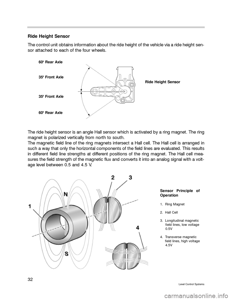
The control unit obtains information about the ride height of the vehicle via a ride height sen-
sor attached to each of the four wheels.
The ride height sensor is an angle Hall sensor which is activated by a ring magnet. The ring
magnet is polarized vertically from north to south.
The magnetic field line of the ring magnets intersect a Hall cell. The Hall cell is arranged in
such a way that only the horizontal components of the field lines are evaluated. This results
in different field line strengths at different positions of the ring magnet. The Hall cell mea-
sures the field strength of the magnetic flux and converts it into an analog signal with a volt-
age level between 0.5 and 4.5 V.
600Rear Axle
350Front Axle
350Front Axle
600Rear Axle
Ride Height Sensor
Sensor Principle of
Operation
1. Ring Magnet
2. Hall Cell
3. Longitudinal magnetic
field lines, low voltage
0.5V
4. Transverse magnetic
field lines, high voltage
4.5V
Page 33 of 57
33
Level Control Systems
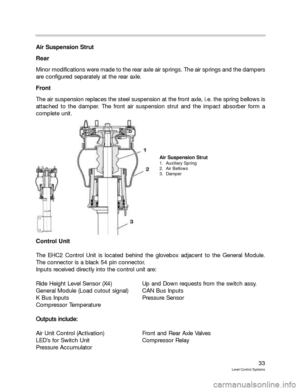
Air Suspension Strut
Rear
Minor modifications were made to the rear axle air springs. The air springs and the dampers
are configured separately at the rear axle.
Front
The air suspension replaces the steel suspension at the front axle, i.e. the spring bellows is
attached to the damper. The front air suspension strut and the impact absorber form a
complete unit.
Control Unit
The EHC2 Control Unit is located behind the glovebox adjacent to the General Module.
The connector is a black 54 pin connector.
Inputs received directly into the control unit are:
Ride Height Level Sensor (X4) Up and Down requests from the switch assy.
General Module (Load cutout signal) CAN Bus Inputs
K Bus Inputs Pressure Sensor
Compressor Temperature
O Ou
ut
tp
pu
ut
ts
s
i
in
nc
cl
lu
ud
de
e:
:
Air Unit Control (Activation) Front and Rear Axle Valves
LED’s for Switch Unit Compressor Relay
Pressure Accumulator
Air Suspension Strut
1. Auxiliary Spring
2. Air Bellows
3. Damper
Page 41 of 57
41
Level Control Systems
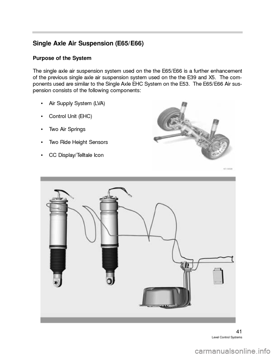
Single Axle Air Suspension (E65/E66)
Purpose of the System
The single axle air suspension system used on the the E65/E66 is a further enhancement
of the previous single axle air suspension system used on the the E39 and X5. The com-
ponents used are similar to the Single Axle EHC System on the E53. The E65/E66 Air sus-
pension consists of the following components:
Air Supply System (LVA)
Control Unit (EHC)
Two Air Springs
Two Ride Height Sensors
CC Display/Telltale Icon
Page 46 of 57
46
Level Control Systems
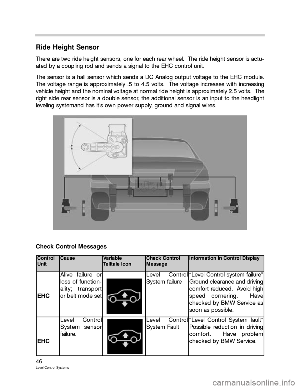
Ride Height Sensor
There are two ride height sensors, one for each rear wheel. The ride height sensor is actu-
ated by a coupling rod and sends a signal to the EHC control unit.
The sensor is a hall sensor which sends a DC Analog output voltage to the EHC module.
The voltage range is approximately .5 to 4.5 volts. The voltage increases with increasing
vehicle height and the nominal voltage at normal ride height is approximately 2.5 volts. The
right side rear sensor is a double sensor, the additional sensor is an input to the headlight
leveling systemand has it’s own power supply, ground and signal wires.
Check Control Messages
Control
UnitCauseVariable
Telltale IconCheck Control
MessageInformation in Control Display
EHC
Alive failure or
loss of function-
ality; transport
or belt mode setLevel Control
System failure“Level Control system failure”
Ground clearance and driving
comfort reduced. Avoid high
speed cornering. Have
checked by BMW Service as
soon as possible.
EHC
Level Control
System sensor
failure.Level Control
System Fault“Level Control System fault”
Possible reduction in driving
comfort. Have problem
checked by BMW Service.
Page 51 of 57
51
Level Control Systems
Kerb (Curb) Mode
The Kerb mode prevents the inclination caused by the vehicle mounting an obstacle with
ine wheel from being compensated. Compensation would cause a renewed inclination of
the vehicle and result in a renewed control operation after the vehicle comes off the obsta-
cle.
The Kerb Mode is activated when the height difference between the left and right sides of
the vehicle is > 32mm for the E65/E66 with single axle air suspension and >24mm for the
E39/E53 with single axle air suspension and lasts longer than 0.9s. Twisting (also over both
axles) > 45mm must occur for the E53 with twin axle air suspension.
There must be no speed signal present. The system switches from single wheel control to
axle control.
The Kerb mode is quit when the difference between the left and right sides of the vehicle is
< 28mm for the single axle air suspension and lasts longer than 0.9s when the speed is
greater than > 1km/h.
If the system switches from Kerb mode to Sleep mode, this status is stored in the
EEPROM.
If the vehicle is loaded or unloaded in Kerb mode, the mean value of the axle is calculated
by the control unit. The value is calculated in the control unit from the changes in ride level
of the spring travel on the left and right sides.
A change in ride level is initiated if the mean value of compression or rebound at the axle is
outside the tolerance band of +/- 10mm. The left and right sides of the vehicle are raised
or lowered in parallel. The height difference between the two sides is maintained.
Curve
Since rolling motions have a direct impact on the measured ride level, an unwanted control
operation would be initiated during longer instances of cornering with an appropriate roll
angle in spite of the slow filtering of the Drive mode. The control operations during corner-
ing would cause displacement of the air volume from the outer side to the inner side of the
curve. Once the curve is completed, this would produce an inclination which would result
in a further control operation. The Curve mode prevents this control operation whereby
when cornering is recognized slow filtering is stopped and a potential control operation that
has started is terminated.
The Curve mode is activated for the E65/E66 single axle EHC and for the E53 twin axle
suspension for a lateral acceleration of > 2m/s
2and deactivated at < 1.5 m/s2.
The lateral acceleration is recorded by the rotation rate sensor.
Page 56 of 57
56
Level Control Systems
Review Questions
1. The EHC control module on the E65/E66 is connected to the Bus.
2. List the operating modes that are specific to the E65/E66 Air Suspension System:
3. Why is the accumulator needed on the dual axle EHC system?
4. List the components specific to the Dual Axle EHC system:
5. Which 2 Buses system are connected to the EHC control module on the Dual Axle EHC
system?
6. What components are replaceable on the LVA?
7. What are the 3 possible ride height setting on the Dual Axle EHC system?
8. What type of sensor is used for ride height measurement?