BMW 740LI 2014 Owners Manual
Manufacturer: BMW, Model Year: 2014, Model line: 740LI, Model: BMW 740LI 2014Pages: 251, PDF Size: 5.75 MB
Page 171 of 251
Danger of burns
Only hold the hot lighter by its knob; oth‐
erwise, there is the danger of getting burned.
Switch off the ignition and take the remote
control with you when leaving the vehicle so
that children cannot use the lighter and burn
themselves.◀
Replace the cover after use
Reinsert the lighter or socket cover after
use, otherwise objects may get into the lighter
socket or fixture and cause a short circuit.◀
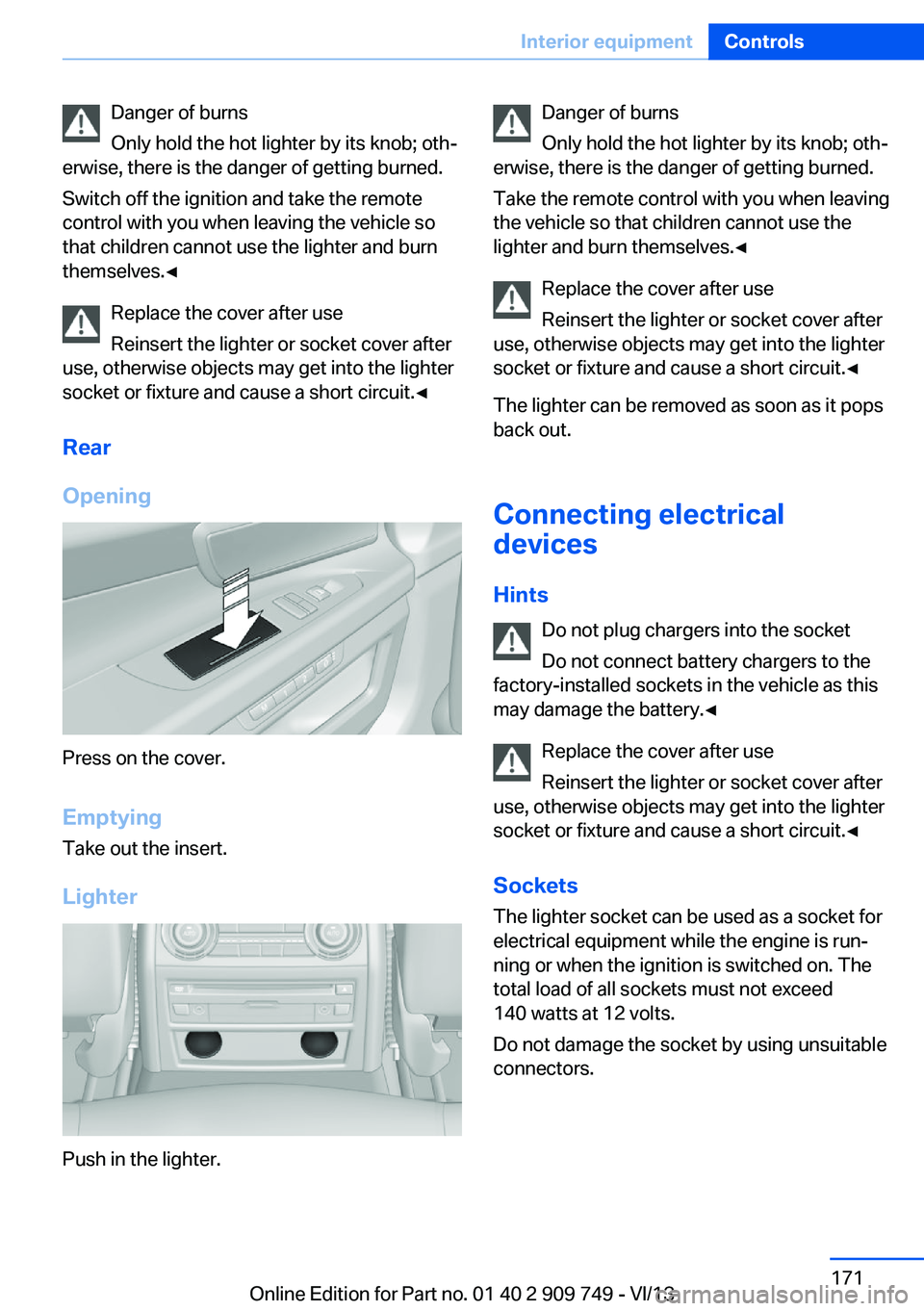
Rear
Opening
Press on the cover.
Emptying Take out the insert.
Lighter
Push in the lighter.
Danger of burns
Only hold the hot lighter by its knob; oth‐
erwise, there is the danger of getting burned.
Take the remote control with you when leaving
the vehicle so that children cannot use the
lighter and burn themselves.◀
Replace the cover after use
Reinsert the lighter or socket cover after
use, otherwise objects may get into the lighter
socket or fixture and cause a short circuit.◀
The lighter can be removed as soon as it pops
back out.
Connecting electrical
devices
Hints Do not plug chargers into the socket
Do not connect battery chargers to the
factory-installed sockets in the vehicle as this
may damage the battery.◀
Replace the cover after use
Reinsert the lighter or socket cover after
use, otherwise objects may get into the lighter
socket or fixture and cause a short circuit.◀
Sockets
The lighter socket can be used as a socket for
electrical equipment while the engine is run‐
ning or when the ignition is switched on. The
total load of all sockets must not exceed
140 watts at 12 volts.
Do not damage the socket by using unsuitable
connectors.Seite 171Interior equipmentControls171
Online Edition for Part no. 01 40 2 909 749 - VI/13
Page 172 of 251
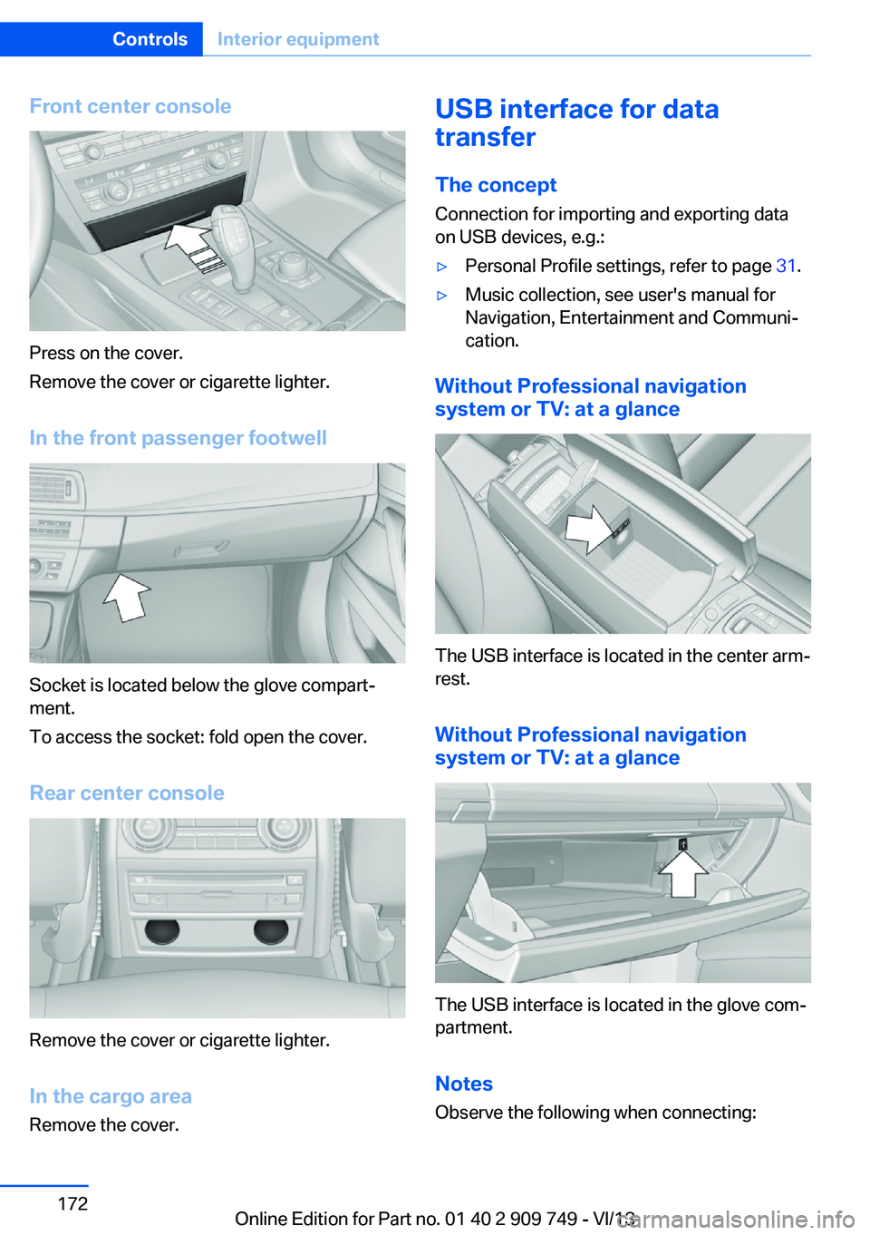
Front center console
Press on the cover.
Remove the cover or cigarette lighter.
In the front passenger footwell
Socket is located below the glove compart‐
ment.
To access the socket: fold open the cover.
Rear center console
Remove the cover or cigarette lighter.
In the cargo area Remove the cover.
USB interface for data
transfer
The concept Connection for importing and exporting data
on USB devices, e.g.:▷Personal Profile settings, refer to page 31.▷Music collection, see user's manual for
Navigation, Entertainment and Communi‐
cation.
Without Professional navigation
system or TV: at a glance
The USB interface is located in the center arm‐
rest.
Without Professional navigation
system or TV: at a glance
The USB interface is located in the glove com‐
partment.
Notes
Observe the following when connecting:
Seite 172ControlsInterior equipment172
Online Edition for Part no. 01 40 2 909 749 - VI/13
Page 173 of 251
▷Do not use force when plugging the con‐
nector into the USB interface.▷Do not connect devices such as fans or
lamps to the USB interface.▷Do not connect USB hard drives.▷Do not use the USB interface to recharge
external devices.
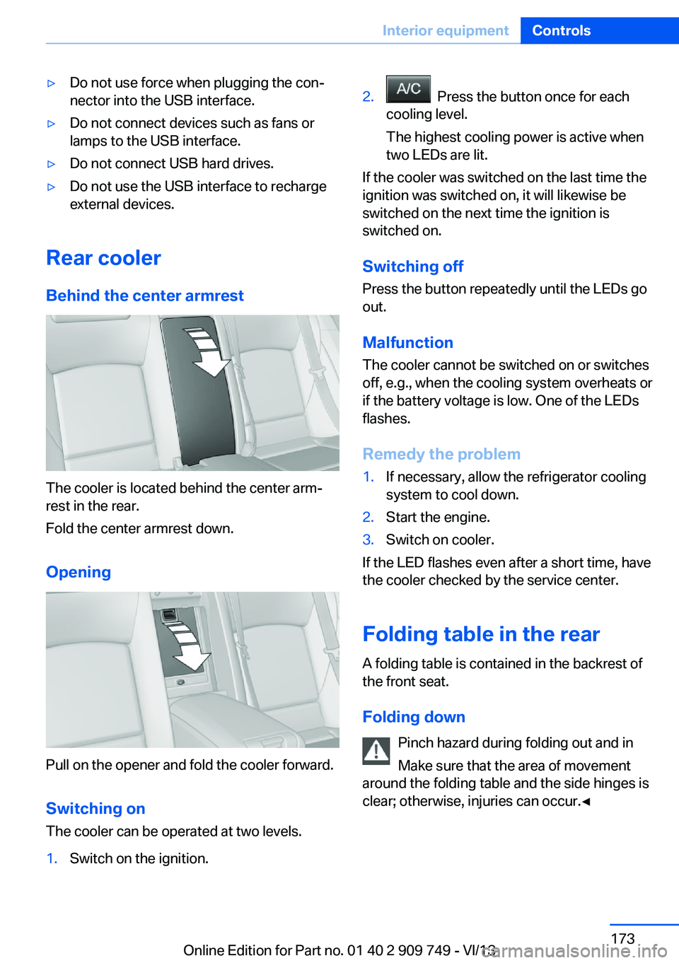
Rear cooler
Behind the center armrest
The cooler is located behind the center arm‐
rest in the rear.
Fold the center armrest down.
Opening
Pull on the opener and fold the cooler forward. Switching onThe cooler can be operated at two levels.
1.Switch on the ignition.2. Press the button once for each
cooling level.
The highest cooling power is active when
two LEDs are lit.
If the cooler was switched on the last time the
ignition was switched on, it will likewise be
switched on the next time the ignition is
switched on.
Switching off
Press the button repeatedly until the LEDs go
out.
Malfunction
The cooler cannot be switched on or switches
off, e.g., when the cooling system overheats or
if the battery voltage is low. One of the LEDs
flashes.
Remedy the problem
1.If necessary, allow the refrigerator cooling
system to cool down.2.Start the engine.3.Switch on cooler.
If the LED flashes even after a short time, have
the cooler checked by the service center.
Folding table in the rear
A folding table is contained in the backrest of
the front seat.
Folding down Pinch hazard during folding out and in
Make sure that the area of movement
around the folding table and the side hinges is
clear; otherwise, injuries can occur.◀
Seite 173Interior equipmentControls173
Online Edition for Part no. 01 40 2 909 749 - VI/13
Page 174 of 251
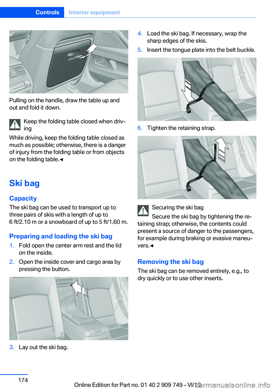
Pulling on the handle, draw the table up and
out and fold it down.
Keep the folding table closed when driv‐
ing
While driving, keep the folding table closed as
much as possible; otherwise, there is a danger
of injury from the folding table or from objects
on the folding table.◀
Ski bag
Capacity The ski bag can be used to transport up to
three pairs of skis with a length of up to
6 ft/2.10 m or a snowboard of up to 5 ft/1.60 m.
Preparing and loading the ski bag
1.Fold open the center arm rest and the lid
on the inside.2.Open the inside cover and cargo area by
pressing the button.3.Lay out the ski bag.4.Load the ski bag. If necessary, wrap the
sharp edges of the skis.5.Insert the tongue plate into the belt buckle.6.Tighten the retaining strap.
Securing the ski bag
Secure the ski bag by tightening the re‐
taining strap; otherwise, the contents could
present a source of danger to the passengers,
for example during braking or evasive maneu‐
vers.◀
Removing the ski bag The ski bag can be removed entirely, e.g., to
dry quickly or to use other inserts.
Seite 174ControlsInterior equipment174
Online Edition for Part no. 01 40 2 909 749 - VI/13
Page 175 of 251
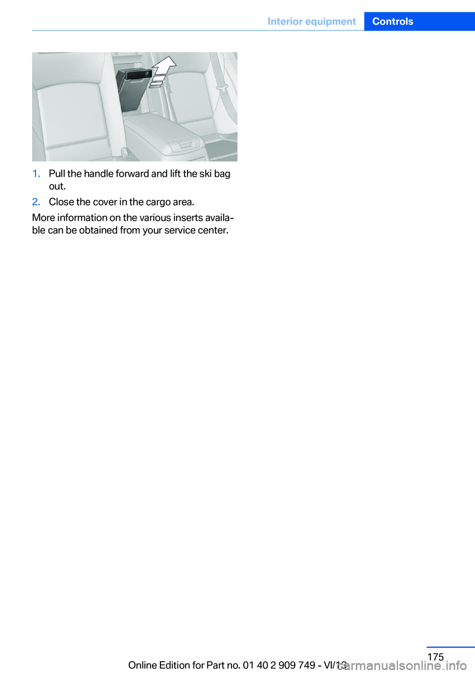
1.Pull the handle forward and lift the ski bag
out.2.Close the cover in the cargo area.
More information on the various inserts availa‐
ble can be obtained from your service center.
Seite 175Interior equipmentControls175
Online Edition for Part no. 01 40 2 909 749 - VI/13
Page 176 of 251
Storage compartmentsVehicle equipmentAll standard, country-specific and optional
equipment that is offered in the model series is
described in this chapter. Therefore, equip‐
ment is also described that is not available in a
vehicle, e. g., because of the selected optional
equipment or country variant. This also applies
for safety-related functions and systems.
Notes No loose objects in the passenger com‐
partment
Do not stow any objects in the passenger
compartment without securing them; other‐
wise, they may present a danger to occupants
for instance during braking and avoidance ma‐
neuvers.◀
Do not place anti-slip mats on the dash‐
board
Do not place anti-slip mats on the dashboard.
The mat materials could damage the dash‐
board.◀
Storage compartments
The following storage compartments are avail‐
able in the vehicle interior:▷Glove compartment on the driver's and
front passenger side, refer to page 176.▷Storage compartment in the center arm‐
rest, refer to page 177, in the front and
rear.▷Compartments in the doors.▷Pockets on the backrests of the front
seats.▷Net in the front passenger footwell.Glove compartment
Front passenger side
Note Close the glove compartment again im‐
mediately
Close the glove compartment immediately af‐
ter use while driving; otherwise, injury may oc‐
cur during accidents.◀
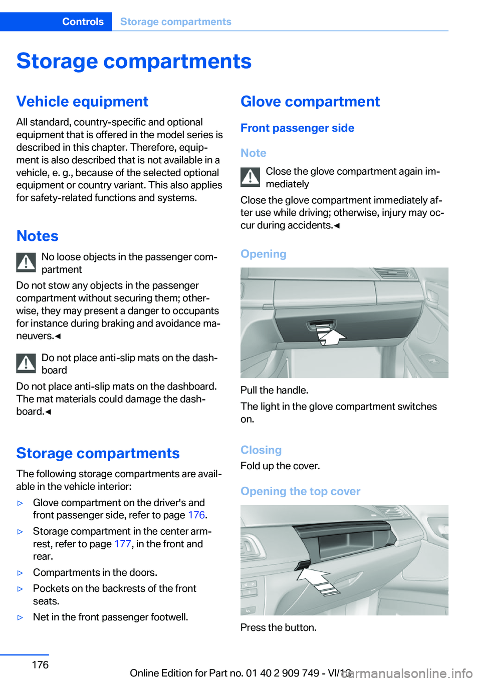
Opening
Pull the handle.
The light in the glove compartment switches
on.
ClosingFold up the cover.
Opening the top cover
Press the button.
Seite 176ControlsStorage compartments176
Online Edition for Part no. 01 40 2 909 749 - VI/13
Page 177 of 251
The top cover opens automatically.Closing the top cover
Press the cover closed.
Driver's side
Note Close the glove compartment again im‐
mediately
Close the glove compartment immediately af‐ ter use while driving; otherwise, injury may oc‐
cur during accidents.◀
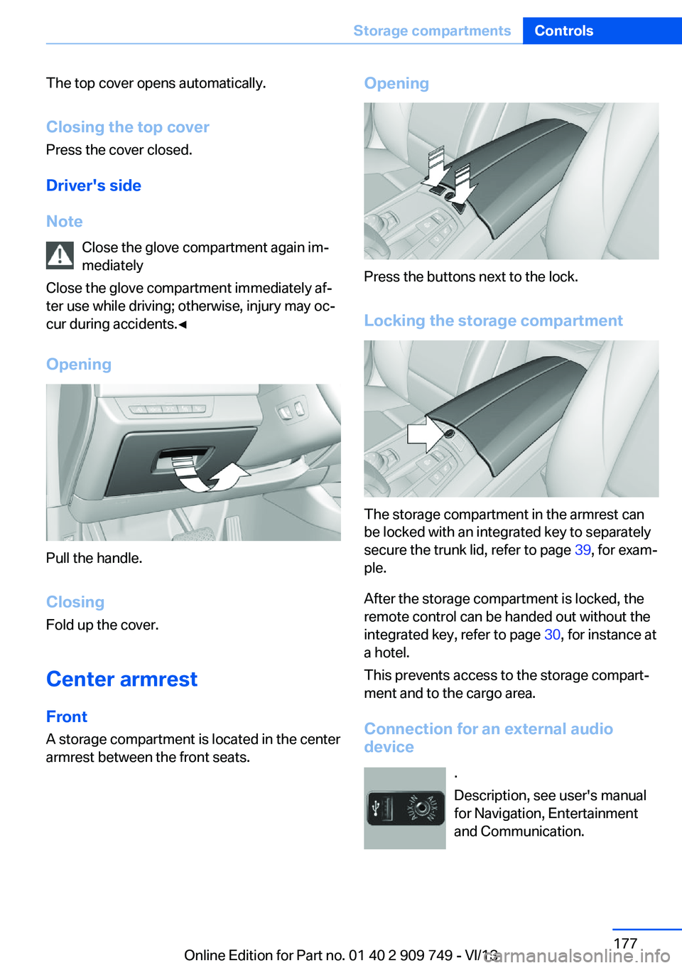
Opening
Pull the handle.
ClosingFold up the cover.
Center armrest
Front A storage compartment is located in the center
armrest between the front seats.
Opening
Press the buttons next to the lock.
Locking the storage compartment
The storage compartment in the armrest can
be locked with an integrated key to separately
secure the trunk lid, refer to page 39, for exam‐
ple.
After the storage compartment is locked, the
remote control can be handed out without the
integrated key, refer to page 30, for instance at
a hotel.
This prevents access to the storage compart‐
ment and to the cargo area.
Connection for an external audio
device
.
Description, see user's manual
for Navigation, Entertainment
and Communication.
Seite 177Storage compartmentsControls177
Online Edition for Part no. 01 40 2 909 749 - VI/13
Page 178 of 251
RearA storage compartment is located in the center
armrest between the seats.
Opening
Depending on the equipment in your vehicle,
the button is in the depression at the front of
the center armrest or on top of the center arm‐ rest.
Cupholders
Hints Shatter-proof containers and no hot
drinks
Use light and shatter-proof containers and do
not transport hot drinks. Otherwise, there is
the increased danger of injury in an accident.◀
Unsuitable containers
Do not forcefully push unsuitable con‐
tainers into the cupholders. This may result in
damage.◀
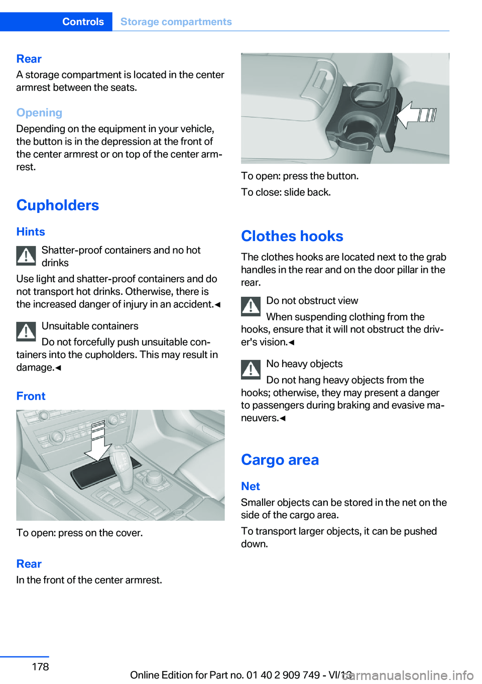
Front
To open: press on the cover.
Rear In the front of the center armrest.
To open: press the button.
To close: slide back.
Clothes hooks
The clothes hooks are located next to the grab
handles in the rear and on the door pillar in the
rear.
Do not obstruct view
When suspending clothing from the
hooks, ensure that it will not obstruct the driv‐
er's vision.◀
No heavy objects
Do not hang heavy objects from the
hooks; otherwise, they may present a danger
to passengers during braking and evasive ma‐
neuvers.◀
Cargo area Net
Smaller objects can be stored in the net on the
side of the cargo area.
To transport larger objects, it can be pushed
down.
Seite 178ControlsStorage compartments178
Online Edition for Part no. 01 40 2 909 749 - VI/13
Page 179 of 251
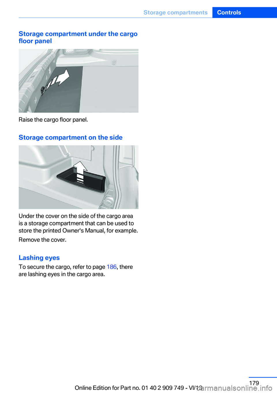
Storage compartment under the cargofloor panel
Raise the cargo floor panel.
Storage compartment on the side
Under the cover on the side of the cargo area
is a storage compartment that can be used to
store the printed Owner's Manual, for example.
Remove the cover.
Lashing eyes To secure the cargo, refer to page 186, there
are lashing eyes in the cargo area.
Seite 179Storage compartmentsControls179
Online Edition for Part no. 01 40 2 909 749 - VI/13
Page 180 of 251

Online Edition for Part no. 01 40 2 909 749 - VI/13