check engine BMW 750I XDRIVE 2014 User Guide
[x] Cancel search | Manufacturer: BMW, Model Year: 2014, Model line: 750I XDRIVE, Model: BMW 750I XDRIVE 2014Pages: 251, PDF Size: 5.75 MB
Page 129 of 251
Integral Active SteeringThe concept
Integral Active Steering is a combination of Ac‐
tive Steering and rear axle steering.
Active Steering varies the steering angle of the
wheels in relation to the steering wheel move‐
ment as a function of the speed.
At speeds up to approx. 37 mph/60 km/h, e.g.,
in curves, the steering angle is increased, i.e.,
steering becomes more direct.
The rear axle steering acts to increase maneu‐
verability by turning the rear wheels slightly in
a direction opposite to the front wheels.
At higher speeds, the steering angle is increas‐
ingly reduced.
The rear wheels are turned to the same angle
as the front wheels.
In critical situations, Integral Active Steering
can specifically steer the front and rear wheels
to stabilize the vehicle before the driver inter‐
venes, e.g., when braking where road condi‐
tions differ on the left and right sides of the ve‐
hicle.
InitializingIn rare cases, it may become necessary to initi‐
alize the Integral Active Steering.
The warning lamp lights up. A Check
Control message is displayed.1.With the engine running, turn the steering
wheel all the way to the left and right sev‐
eral times in a uniform manner until the
warning lamp disappears.2.Have the system checked if the warning
lamp does not go out after moving the
steering wheel approx. 6 times or if the
steering wheel is at an angle.Using snow chains
Note When snow chains are in use, refer to
page 209, rear wheel steering is deactivated.
Programs The system offers several different programs.
The programs can be selected via the Driving
Dynamics Control, refer to page 130.
SPORT
Consistently sporty tuning of the Integral Ac‐
tive Steering for greater driving agility.
COMFORT Balanced tuning between the COMFORT+ and
SPORT programs.
COMFORT+
Consistently comfort-oriented tuning of the In‐
tegral Active Steering for optimal traveling
comfort.
Malfunction
In the event of a malfunction, the steering
wheel must be turned further, while the vehicle
responds more sensitively to steering wheel
movements in the higher speed range.
The stability-enhancing intervention may be
deactivated.
Proceed cautiously and drive defensively.
Have the system checked.
Self-leveling suspension The concept
The self-leveling suspension keeps the vehicle height and ground clearance constant. The
height of the vehicle at the rear axle is main‐
tained at a predefined level under all load con‐
ditions.Seite 129Driving stability control systemsControls129
Online Edition for Part no. 01 40 2 909 749 - VI/13
Page 145 of 251
PDC Park Distance ControlThe concept
PDC supports you when parking. Objects that
you are approaching slowly in front of or be‐
hind your vehicle are indicated by:▷Signal tones.▷Visual display.
General information
Measurements are made by ultrasound sen‐
sors in the bumpers.
The range is approx. 6 ft/2 m.
An acoustic warning is first given:
▷By the front sensors and the two rear cor‐
ner sensors at approx. 24 in/60 cm.▷By the rear middle sensors at approx.
5 ft/1.50 m.
Notes
Check the traffic situation as well
PDC cannot serve as a substitute for the
driver's personal judgment of the traffic situa‐
tion. Check the traffic situation around the ve‐
hicle with your own eyes. Otherwise, an acci‐
dent could result from road users or objects
located outside of the PDC detection range.
Loud noises from outside and inside the vehi‐ cle may prevent you from hearing the PDC's
signal tone.◀
Avoid driving quickly with PDC
Avoid approaching an object quickly.
Avoid driving away quickly while PDC is not yet
active.
For technical reasons, the system may other‐
wise be too late in issuing a warning.◀
At a glance
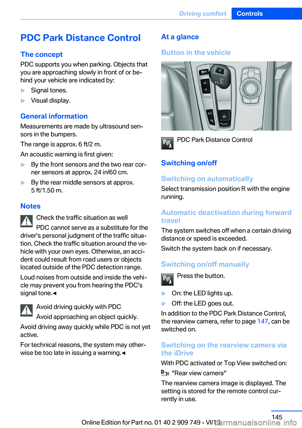
Button in the vehicle
PDC Park Distance Control
Switching on/off
Switching on automatically Select transmission position R with the engine
running.
Automatic deactivation during forward
travel
The system switches off when a certain driving
distance or speed is exceeded.
Switch the system back on if necessary.
Switching on/off manually Press the button.
▷On: the LED lights up.▷Off: the LED goes out.
In addition to the PDC Park Distance Control,
the rearview camera, refer to page 147, can be
switched on.
Switching on the rearview camera viathe iDrive
With PDC activated or Top View switched on:
"Rear view camera"
The rearview camera image is displayed. The
setting is stored for the remote control cur‐
rently in use.
Seite 145Driving comfortControls145
Online Edition for Part no. 01 40 2 909 749 - VI/13
Page 147 of 251
▷Due to other ultrasound sources, e.g.,
sweeping machines, high pressure steam
cleaners or neon lights.
Malfunction
A Check Control message is displayed.
The range of the sensors is shown as a shaded
area on the Control Display.
PDC has failed. Have the system checked.
To ensure full operability:
▷Keep the sensors clean and free of ice.▷When using high-pressure washers, do not
spray the sensors for long periods and
maintain a distance of at least 12 in/30 cm.
Surround View
The concept Surround View comprises various camera as‐
sistance systems that help the driver when
parking, maneuvering, and at complex exits
and intersections.
▷Rearview camera, refer to page 147▷Side View, refer to page 149.▷Top View, refer to page 151.
Backup camera
The concept
The backup camera provides assistance in
parking and maneuvering backwards. The area
behind the vehicle is shown on the Control
Display.
Hints Check the traffic situation as well
Check the traffic situation around the ve‐
hicle with your own eyes. Otherwise, an acci‐
dent could result from road users or objects lo‐
cated outside the picture area of the backup
camera.◀
At a glance
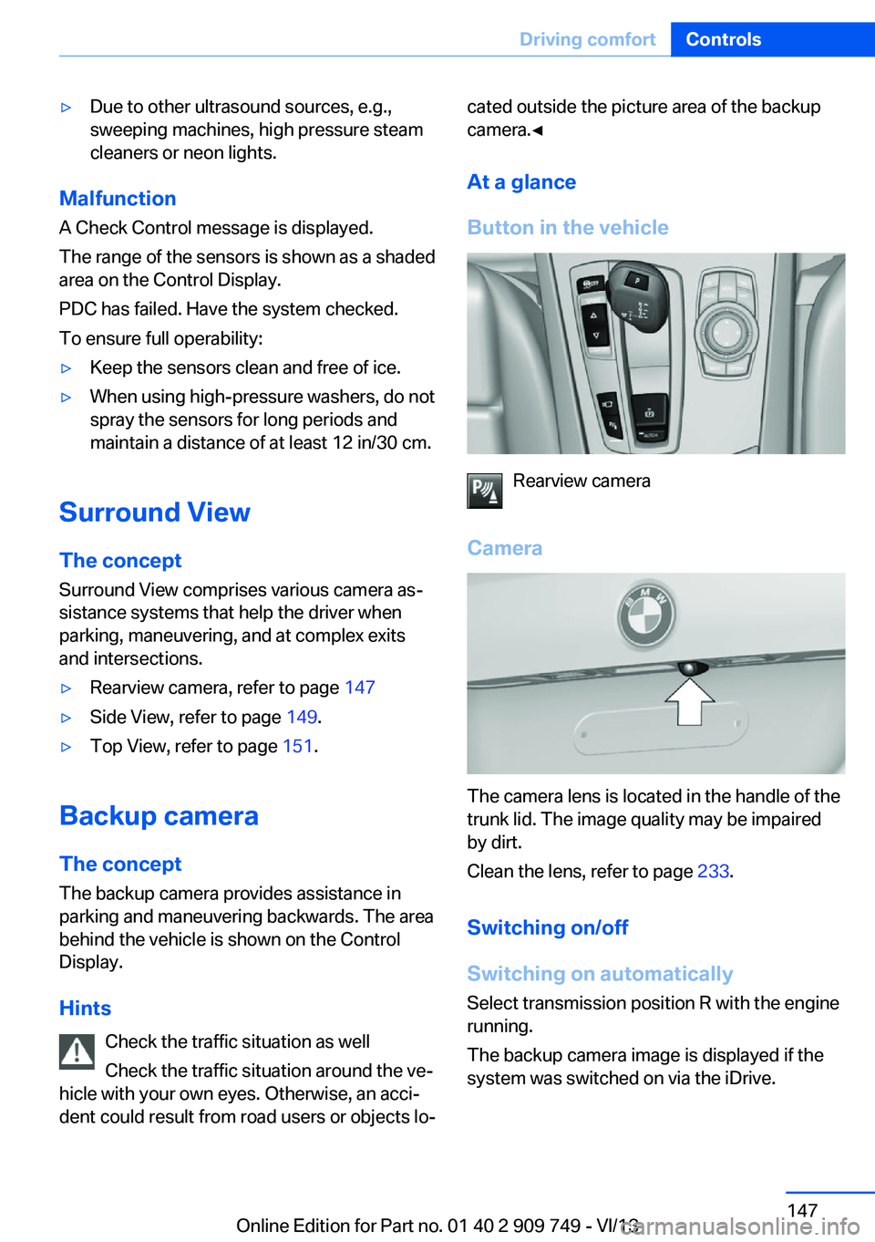
Button in the vehicle
Rearview camera
Camera
The camera lens is located in the handle of the
trunk lid. The image quality may be impaired
by dirt.
Clean the lens, refer to page 233.
Switching on/off
Switching on automatically Select transmission position R with the engine
running.
The backup camera image is displayed if the
system was switched on via the iDrive.
Seite 147Driving comfortControls147
Online Edition for Part no. 01 40 2 909 749 - VI/13
Page 151 of 251
System limits
The cameras capture a maximum range of
330 ft/100 m.
Top View
The concept Top View assists you in parking and maneu‐
vering. The area around the doors and the road
area around the vehicle are shown on the Con‐
trol Display for this purpose.
General information
The image is captured by two cameras integrated in the exterior mirrors and by the
backup camera.
The range is at least 7 ft/2 m to the side and
rear.
In this way, obstacles up to the height of the
exterior mirrors are detected early.
Notes Check the traffic situation as well
Check the traffic situation around the ve‐
hicle with your own eyes. Otherwise, an acci‐
dent could result from road users or objects lo‐
cated outside the picture area of the
cameras.◀
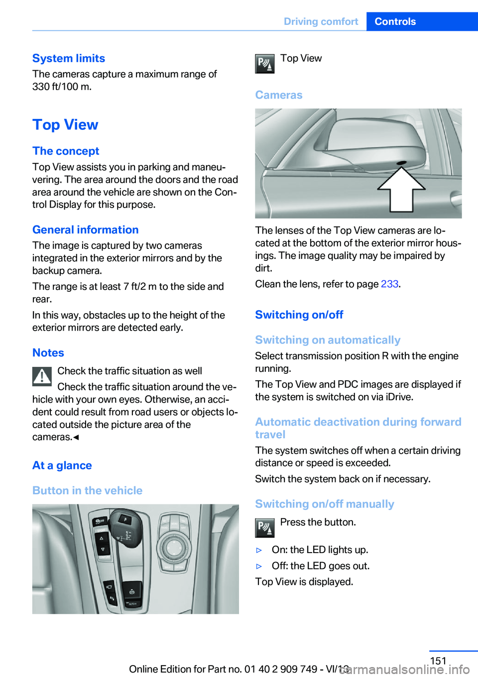
At a glance
Button in the vehicleTop View
Cameras
The lenses of the Top View cameras are lo‐
cated at the bottom of the exterior mirror hous‐
ings. The image quality may be impaired by
dirt.
Clean the lens, refer to page 233.
Switching on/off
Switching on automatically Select transmission position R with the engine
running.
The Top View and PDC images are displayed if
the system is switched on via iDrive.
Automatic deactivation during forward
travel
The system switches off when a certain driving
distance or speed is exceeded.
Switch the system back on if necessary.
Switching on/off manually Press the button.
▷On: the LED lights up.▷Off: the LED goes out.
Top View is displayed.
Seite 151Driving comfortControls151
Online Edition for Part no. 01 40 2 909 749 - VI/13
Page 173 of 251
▷Do not use force when plugging the con‐
nector into the USB interface.▷Do not connect devices such as fans or
lamps to the USB interface.▷Do not connect USB hard drives.▷Do not use the USB interface to recharge
external devices.
Rear cooler
Behind the center armrest
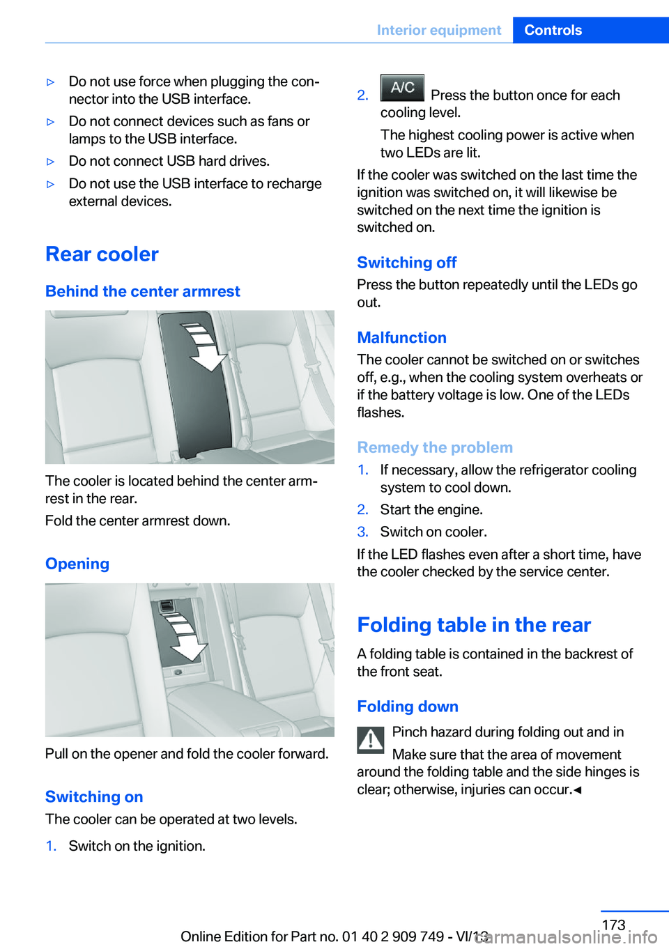
The cooler is located behind the center arm‐
rest in the rear.
Fold the center armrest down.
Opening
Pull on the opener and fold the cooler forward. Switching onThe cooler can be operated at two levels.
1.Switch on the ignition.2. Press the button once for each
cooling level.
The highest cooling power is active when
two LEDs are lit.
If the cooler was switched on the last time the
ignition was switched on, it will likewise be
switched on the next time the ignition is
switched on.
Switching off
Press the button repeatedly until the LEDs go
out.
Malfunction
The cooler cannot be switched on or switches
off, e.g., when the cooling system overheats or
if the battery voltage is low. One of the LEDs
flashes.
Remedy the problem
1.If necessary, allow the refrigerator cooling
system to cool down.2.Start the engine.3.Switch on cooler.
If the LED flashes even after a short time, have
the cooler checked by the service center.
Folding table in the rear
A folding table is contained in the backrest of
the front seat.
Folding down Pinch hazard during folding out and in
Make sure that the area of movement
around the folding table and the side hinges is
clear; otherwise, injuries can occur.◀
Seite 173Interior equipmentControls173
Online Edition for Part no. 01 40 2 909 749 - VI/13
Page 188 of 251
Saving fuelVehicle equipmentAll standard, country-specific and optional
equipment that is offered in the model series is
described in this chapter. Therefore, equip‐
ment is also described that is not available in a
vehicle, e. g., because of the selected optional
equipment or country variant. This also applies
for safety-related functions and systems.
General information Your vehicle contains advanced technology for
the reduction of fuel consumption and emis‐
sions.
Fuel consumption depends on a number of dif‐
ferent factors.
The implementation of certain measures, driv‐
ing style and regular maintenance can have an
influence on fuel consumption and on the envi‐
ronmental impact.
Remove unnecessary cargoAdditional weight increases fuel consumption.
Remove attached parts
following use
Remove auxiliary mirrors, roof or rear luggage
racks which are no longer required following
use.
Attached parts on the vehicle impair the aero‐
dynamics and increase the fuel consumption.Close the windows and glass
sunroof
Driving with the glass sunroof and windows
open results in increased air resistance and
raises fuel consumption.
Tires General information
Tires can affect fuel consumption values in
various ways, for instance fuel consumption
can be influenced by the size of the tires.
Check the tire inflation pressure
regularly
Check and, if necessary, correct the tire infla‐
tion pressure at least twice a month and before
starting on a long trip.
Low tire inflation pressure increases rolling re‐
sistance and thus raises fuel consumption and
tire wear.
Drive away without delay Do not wait for the engine to warm-up while
the vehicle remains stationary. Start driving
right away, but at moderate engine speeds.
This is the fastest way for the cold engine to
reach its operating temperature.
Look well ahead when
driving
Avoid unnecessary acceleration and braking.
By maintaining a suitable distance to the vehi‐
cle driving ahead of you.
Driving smoothly and looking ahead reduces
fuel consumption.Seite 188Driving tipsSaving fuel188
Online Edition for Part no. 01 40 2 909 749 - VI/13
Page 212 of 251
Engine oilVehicle equipment
All standard, country-specific and optional
equipment that is offered in the model series is
described in this chapter. Therefore, equip‐
ment is also described that is not available in a
vehicle, e. g., because of the selected optional
equipment or country variant. This also applies
for safety-related functions and systems.
General information The engine oil consumption is dependent on
the driving style and driving conditions. When
a sporty driving style is used, the engine oil
consumption, for example, is clearly higher.
Therefore, regularly check the engine oil level
after refueling.
Checking the oil level
electronically
Status display
The concept The oil level is monitored electronically during
driving and shown on the Control Display.
If the oil level reaches the minimum level, a
check control message is displayed.
Requirements Depending on the previous displays, the status
display is displayed when the engine is running
or after the vehicle has been driven for at least
30 minutes.
Displaying the oil level1."Vehicle Info"2."Vehicle status"3. "Engine oil level"
Oil level display messages
Different messages appear on the display de‐
pending on the oil level. Pay attention to these
messages.
If oil level is too low, immediately add 1 US
quart/liter of oil.
Take care not to add too much engine oil.
Too much engine oil
Have the vehicle checked immediately;
otherwise, surplus oil can lead to engine dam‐
age.◀
Detailed measurement
The concept
In the detailed measurement the oil level is
checked and displayed via a scale.
During the measurement, the idle speed is in‐
creased somewhat.
General information
A detailed measurement is only possible with
certain engines.
Requirements
▷Automatic transmission: selector lever in
transmission position N or P and accelera‐
tor not depressed.▷Vehicle is on a level road and the engine is
running at operating temperature.
Performing a detailed measurement
In order to perform a detailed measurement of
the engine oil level:
1."Vehicle Info"2."Vehicle status"Seite 212MobilityEngine oil212
Online Edition for Part no. 01 40 2 909 749 - VI/13
Page 213 of 251
3. "Measure engine oil level"4."Start measurement"
The oil level is checked and displayed via a
scale.
Duration: approx. 1 minute.
Adding engine oil 760i/Li: open/close flap
When the flap is closed, it must latch
Filler neck
When the indicator lights up in the instrument
cluster, add 1 US quart/liter of engine oil within
the next 125 miles/200 km.
Protect children
Keep oil, grease, etc., out of reach of chil‐
dren and heed the warnings on the containers
to prevent health risks.◀
Oil types for refilling
Hints No oil additives
Oil additives may lead to engine dam‐
age.◀
Viscosity grades for engine oils
When selecting an engine oil, ensure that
the engine oil belongs to one of the viscosity
grades SAE 0W-40, SAE 0W-30, SAE 5W-40,
and SAE 5W-30 or malfunctions or engine
damage may occur.◀
The engine oil quality is critical for the life of
the engine.
Some types of oils in some cases are not avail‐
able in all countries.
Approved oil typesGasoline engineBMW High Performance SAE 5W-30.BMW Longlife-01.BMW Longlife-01 FE.
Additional information about the approved
types of oils can be requested from the service
center.
Alternative oil types If the approved engine oils are not available, up
to 1 US quart/liter of an oil with the following
specification can be added:
Gasoline engineAPI SM or superior grade specification.
Oil change
An oil change should be carried out by your
service center only.
Seite 213Engine oilMobility213
Online Edition for Part no. 01 40 2 909 749 - VI/13
Page 215 of 251
CoolantVehicle equipmentAll standard, country-specific and optional
equipment that is offered in the model series is
described in this chapter. Therefore, equip‐
ment is also described that is not available in a
vehicle, e. g., because of the selected optional
equipment or country variant. This also applies
for safety-related functions and systems.
General information Danger of burns from hot engine
Do not open the cooling system while
the engine is hot; otherwise, escaping coolant may cause burns.◀
Suitable additives
Only use suitable additives; otherwise,
engine damage may occur. The additives are
harmful to your health.◀
Coolant consists of water and additives.
Not all commercially available additives are
suitable for your vehicle. Ask your service cen‐
ter for suitable additives.
Coolant level
If there is no Min. and Max. mark in the filler
neck of the coolant reservoir, have the coolant
level checked if necessary by your service cen‐
ter and add coolant as needed.
Note Depending on the engine installation, the cool‐
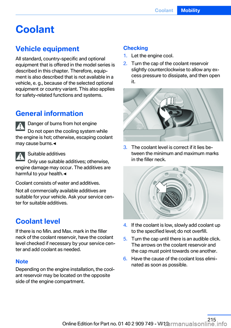
ant reservoir may be located on the opposite side of the engine compartment.Checking1.Let the engine cool.2.Turn the cap of the coolant reservoir
slightly counterclockwise to allow any ex‐
cess pressure to dissipate, and then open
it.3.The coolant level is correct if it lies be‐
tween the minimum and maximum marks
in the filler neck.4.If the coolant is low, slowly add coolant up
to the specified level; do not overfill.5.Turn the cap until there is an audible click.
The arrows on the coolant reservoir and
the cap must point towards one another.6.Have the cause of the coolant loss elimi‐
nated as soon as possible.Seite 215CoolantMobility215
Online Edition for Part no. 01 40 2 909 749 - VI/13
Page 216 of 251
MaintenanceVehicle equipment
All standard, country-specific and optional
equipment that is offered in the model series is
described in this chapter. Therefore, equip‐
ment is also described that is not available in a
vehicle, e. g., because of the selected optional
equipment or country variant. This also applies
for safety-related functions and systems.
BMW Maintenance System The maintenance system directs you to re‐
quired maintenance measures and thereby
supports you in maintaining road safety and
the operational reliability of the vehicle.
Condition Based Service
CBS
Sensors and special algorithms take into ac‐
count the driving conditions of your vehicle.
Based on this, Condition Based Service deter‐
mines the maintenance requirements.
The system makes it possible to adapt the
amount of maintenance you need to your user
profile.
Details on the service requirements, refer to
page 87, can be displayed on the Control Dis‐
play.
Service data in the remote control
Information on the required maintenance is
continuously stored in the remote control.
Your service center will read out this data and
suggest the right array of service procedures
for your vehicle.
Therefore, hand your service specialist the re‐
mote control with which the vehicle was driven
most recently.Storage periods
Storage periods during which the vehicle bat‐
tery was disconnected are not taken into ac‐
count.
If this occurs, have a service center update the
time-dependent maintenance procedures,
such as checking brake fluid and, if necessary,
changing the engine oil and the microfilter/
activated-charcoal filter.
Service history Perform maintenance work at the service cen‐
ter and have them recorded in the vehicle data.
The entries are like a service booklet of the
documentation of regular maintenance.
Displaying entered maintenance work on the
Control Display, refer to page 88.
Service and Warranty
Information Booklet for US
models and Warranty and
Service Guide Booklet for
Canadian models
Please consult your Service and Warranty In‐
formation Booklet for US models and Warranty
and Service Guide Booklet for Canadian mod‐
els for additional information on service re‐
quirements.
Maintenance and repair should be performed
by your service center. Make sure to have reg‐
ular maintenance procedures recorded in the
vehicle's Service and Warranty Information
Booklet for US models, and in the Warranty
and Service Guide Booklet for Canadian mod‐
els. These entries are proof of regular mainte‐
nance.Seite 216MobilityMaintenance216
Online Edition for Part no. 01 40 2 909 749 - VI/13