high BMW 750IL 1989 E32 Level Control System Manual
[x] Cancel search | Manufacturer: BMW, Model Year: 1989, Model line: 750il, Model: BMW 750il 1989 E32Pages: 57, PDF Size: 1.89 MB
Page 3 of 57
3
Level Control Systems
Level Control Systems
Purpose of the System
The primary function of Level Control Systems is to maintain the height of the vehicle as
closely as possible to a predetermined level under all load conditions.
This constant level allows the suspension system to maintain the alignment geometry.
Camber and Toe in are minimally affected when the ride height is consistent. In addition,
the headlight range stays consistent throughout the various operating conditions.
The Level Control System is designed to operate in the event of static changes such as
when passengers are entering or exiting the vehicle or quasi-static such as s when the fuel
tank is emptying while driving.
The Level Control System come in various configurations such as hydraulic (hydropneu-
matic) or pneumatic only systems.
Hydropneumatic systems use high pressure hydraulic fluid which is dampened by a gas
cushion from a nitrogen charged accumulator. These system use and electro-hydraulic
pump or an engine driven piston pump. These systems are installed as follows:
Hydropneumatic Level Control System with electro-hydraulic pump- This
type of system is used on the early 5 Series vehicles (E12 and E28), the 6 Series
(E24) and the early 7 Series (E23). This system uses an electric motor, pump and
an expansion tank which is connected by hydraulic lines to the rear spring struts.
The rear spring struts are also connected to a pair of pressure accumulators which
are “Nitrogen Charged”. There is a control switch which mounted on the rear axle
which monitors the position of the stabilizer bar. Changes in ride height are detect-
ed and the system is regulated to maintain the correct level. During prolonged dyna-
mic movements during acceleration and braking, the level control system is disabled
by an acceleration sensor (mercury switch) and brake light input to the hydraulic
control unit.
Hydropneumatic Level Control System with engine driven piston pump- This
system can be found on the 7 Series (E32 and E38) and the 5 Series Touring (E34).
This configuration is similar in operation to the previous system with a few changes.
There hydraulic pressure now comes from an engine driven piston pump. This
pump is mounted in tandem with the power steering (radial type) pump. The pres-
surized fluid is sent to a control valve which distributes the fluid to the rear spring
struts and pressure accumulators. The control valve is attached to the rear sway
bar by a lever, changes in ride height will move the lever which will influence fluid flow
to the spring struts.
The next generation of BMW Level Control Systems evolved into pneumatic only systems
which are referred to as EHC. EHC will be discussed later in this module.
Page 11 of 57

11
Level Control Systems
LAD Module
With a high pressure applied to the control piston,
the flow resistance is high and the damping force
will be stiff.
The load dependent module is a control valve
that regulates the flow of oil between the strut
and the pressure reservoir.
The control piston in the (LAD) moves in rela-
tion to the pressure applied from the pump.
This movement will regulate the tension on the
inner spring of the module. With only a low
pressure applied, a small amount of tension
will be applied to the spring. Little flow resis-
tance will be developed between the strut and
pressure reservoir. The damping force is soft.
Page 17 of 57
17
Level Control Systems
Air Springs
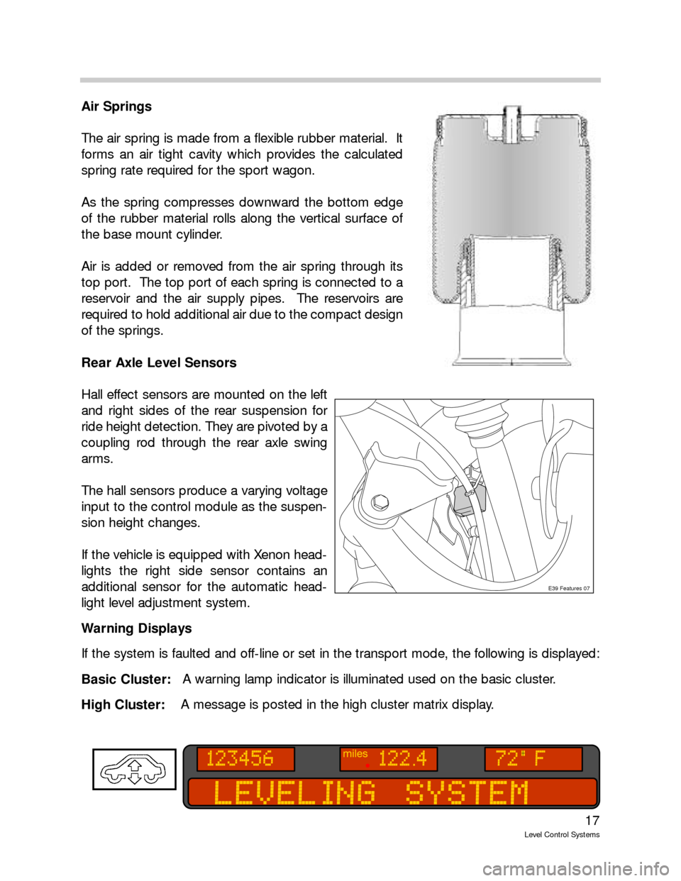
The air spring is made from a flexible rubber material. It
forms an air tight cavity which provides the calculated
spring rate required for the sport wagon.
As the spring compresses downward the bottom edge
of the rubber material rolls along the vertical surface of
the base mount cylinder.
Air is added or removed from the air spring through its
top port. The top port of each spring is connected to a
reservoir and the air supply pipes. The reservoirs are
required to hold additional air due to the compact design
of the springs.
Rear Axle Level Sensors
Hall effect sensors are mounted on the left
and right sides of the rear suspension for
ride height detection. They are pivoted by a
coupling rod through the rear axle swing
arms.
The hall sensors produce a varying voltage
input to the control module as the suspen-
sion height changes.
If the vehicle is equipped with Xenon head-
lights the right side sensor contains an
additional sensor for the automatic head-
light level adjustment system.
Warning Displays
If the system is faulted and off-line or set in the transport mode, the following is displayed:
Basic Cluster:A warning lamp indicator is illuminated used on the basic cluster.
High Cluster: A message is posted in the high cluster matrix display.
E39 Features 07
Page 23 of 57
23
Level Control Systems
Special Operating Modes
Assembly Line Mode (New control module)
The assembly line mode refers to control module manufacturing. New control modules
are stored in a deactivated state. The control programming is not active and must first
be ZCS encoded.
After installing a replacement control module, it must be coded using the DIS or MoDiC.
The instrument cluster fault display will remain illuminated until the control module is
coded.
Transport Mode
The vehicle rolls off the factory assembly line with the EHC control module in the trans-
port mode. The transport mode inflates the air springs to a higher position (approx.
30mm higher) than the normal mode in order to avoid damage during transit.
The system will not respond to any inputs that would alter the height of the vehicle. The
fault indicator (base cluster) is illuminated or instrument cluster matrix display (high clus-
ter) provides the message “Leveling System” to draw attention to the transport mode
setting.
The Service Functions section of the diagnosis program is used to activate/deactivate
the transport mode. Once the transport mode is deactivated, check the vehicle Ride
Height Offset making sure the vehicle rear axle height is to specification.
Control Interrupts
Cornering
To prevent unnecessary suspension adjustments while driving through corners, a “control
interrupt” is built into the system. Above 30MPH the control module monitors the left/right
ride height sensors for a difference of 30mm. Exceeding this difference will put the system
into a control interrupt and no adjustment will take place. The control interrupt last for a
duration of 5 minutes.
Vehicle Lifting
The ride height control is interrupted when the vehicle is raised on a lift or with a jack. The
system monitors the ride height sensor inputs and when the height limit of 90 mm is
exceeded, the control is switched OFF until the vehicle is lowered again.
Page 29 of 57
29
Level Control Systems
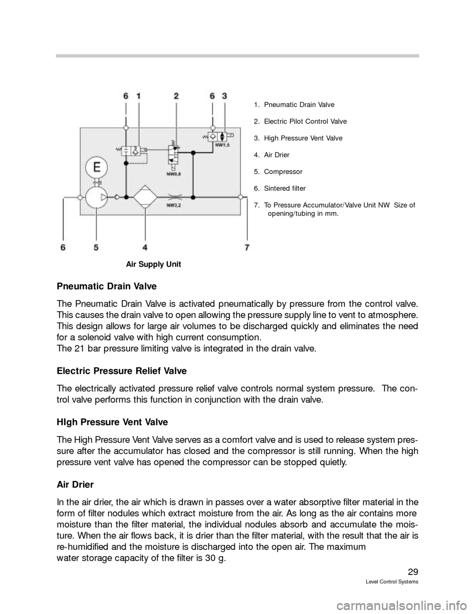
Pneumatic Drain Valve
The Pneumatic Drain Valve is activated pneumatically by pressure from the control valve.
This causes the drain valve to open allowing the pressure supply line to vent to atmosphere.
This design allows for large air volumes to be discharged quickly and eliminates the need
for a solenoid valve with high current consumption.
The 21 bar pressure limiting valve is integrated in the drain valve.
Electric Pressure Relief Valve
The electrically activated pressure relief valve controls normal system pressure. The con-
trol valve performs this function in conjunction with the drain valve.
HIgh Pressure Vent Valve
The High Pressure Vent Valve serves as a comfort valve and is used to release system pres-
sure after the accumulator has closed and the compressor is still running. When the high
pressure vent valve has opened the compressor can be stopped quietly.
Air Drier
In the air drier, the air which is drawn in passes over a water absorptive filter material in the
form of filter nodules which extract moisture from the air. As long as the air contains more
moisture than the filter material, the individual nodules absorb and accumulate the mois-
ture. When the air flows back, it is drier than the filter material, with the result that the air is
re-humidified and the moisture is discharged into the open air. The maximum
water storage capacity of the filter is 30 g.
1. Pneumatic Drain Valve
2. Electric Pilot Control Valve
3. High Pressure Vent Valve
4. Air Drier
5. Compressor
6. Sintered filter
7. To Pressure Accumulator/Valve Unit NW Size of
opening/tubing in mm.
Air Supply Unit
Page 32 of 57
32
Level Control Systems
Ride Height Sensor
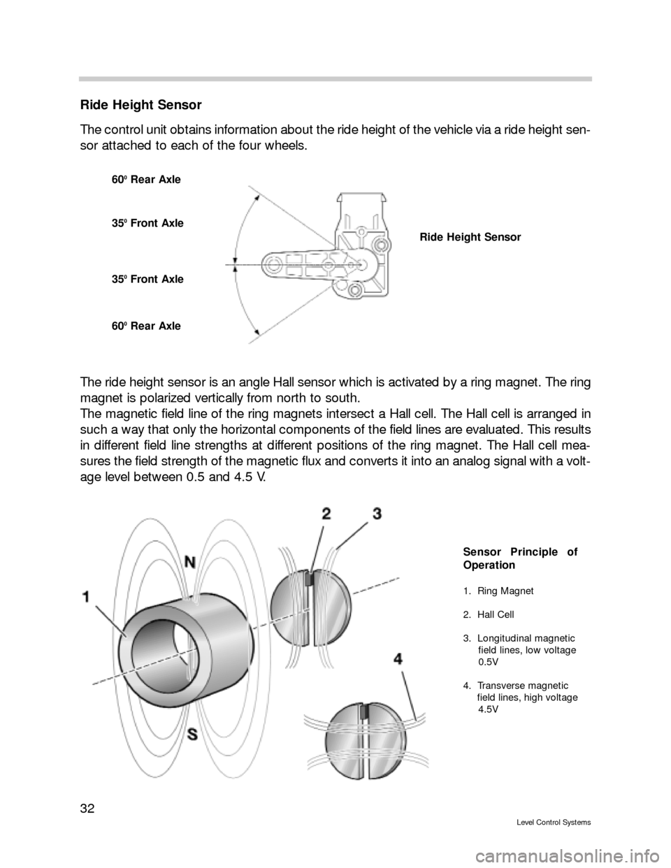
The control unit obtains information about the ride height of the vehicle via a ride height sen-
sor attached to each of the four wheels.
The ride height sensor is an angle Hall sensor which is activated by a ring magnet. The ring
magnet is polarized vertically from north to south.
The magnetic field line of the ring magnets intersect a Hall cell. The Hall cell is arranged in
such a way that only the horizontal components of the field lines are evaluated. This results
in different field line strengths at different positions of the ring magnet. The Hall cell mea-
sures the field strength of the magnetic flux and converts it into an analog signal with a volt-
age level between 0.5 and 4.5 V.
600Rear Axle
350Front Axle
350Front Axle
600Rear Axle
Ride Height Sensor
Sensor Principle of
Operation
1. Ring Magnet
2. Hall Cell
3. Longitudinal magnetic
field lines, low voltage
0.5V
4. Transverse magnetic
field lines, high voltage
4.5V
Page 35 of 57
35
Level Control Systems
Principle of Operation
Ride Height Control Operations
In addition to the automatic ride-height control system for payload compensation, the dri-
ver can set three different vehicle ride heights.
Off-road (+25 mm), high ground clearance to a max. speed of 50 km/h
Standard (0 mm), normal ride level
Access (-35 mm), for entry and exit, loading and unloading to a max. speed of 35 km/h
or can be activated in Standard mode at road speeds < 25 km/h
The various heights are selected by scroll rocker. Light emitting diodes indicate the present
ride height setting.
Ride height can be adjusted from terminal 15 and with the doors closed. The hood and tail-
gate may be open.
The system also controls inclination automatically, like the single axle air suspension.
All control operations are executed without stopping at intermediate levels. The vehicle is
configured pneumatically in such a way that the front and rear axles can be lowered in par-
allel in any load situation. Depending on the load situation, either the front axle or the rear
axle is slightly quicker. On account of the different control speeds, a difference in height
between the two axles is possible during all control operations. If a max. permissible thresh-
old is exceeded, the quicker axle is stopped briefly.
The various levels can be preselected while travelling. Changeover between ride levels is
effected at the speed threshold values defined in the control unit. The control unit monitors
the change-over.
As soon as the driver sets a new target ride level by pressing a button or when a change-
over is initiated automatically by a specific driving condition, the LED for the current ride
level remains lit and the LED for the target ride level begins to flash.
When the new level is reached, the LED for the previous level goes out and the LED for the
new level reached stays lit permanently.
Page 37 of 57
37
Level Control Systems
In addition to the LED indicator, the following text messages can
be displayed in the instrument cluster:
T TR
RA
AI
IL
LE
ER
R
M
MO
OD
DE
E
A coupled trailer is identified via the trailer connector. To avoid damaging the trailer and
the vehicle, changes of vehicle level are generally avoided. The standard level is "frozen."
If the trailer is coupled at a level other than the Standard level, the vehicle ride level is
not changed to Standard unless a button is pressed or the speed threshold for auto-
matic change-over is reached. The standard level is then "frozen" until the trailer con-
nector is disconnected.
R RI
ID
DE
E
H
HE
EI
IG
GH
HT
T
C
CO
ON
NT
TR
RO
OL
L
I
IN
NA
AC
CT
TI
IV
VE
E
Faults in the system and on the control unit which are only identified by the instrument
cluster, e.g. control unit disconnected
R RI
ID
DE
E
H
HE
EI
IG
GH
HT
T
C
CO
ON
NT
TR
RO
OL
L
I
IN
NA
AC
CT
TI
IV
VE
E
+
+
M
MA
AX
X.
.
6
60
0
k
km
m/
/h
h
For safety-critical faults (vehicle is too high or at inclination)
Control Modes
Sleep mode
If the vehicle is parked, it enters Sleep mode after 16 minutes. No further control opera-
tions are executed. A "watch dog" wakes up the control unit for a few minutes every 6
hours (wakeup mode) in order to compensate for possible inclination of the vehicle. (Vehicle
height may only be corrected once as air supply unit only operates with engine running.)
Wake-up
In wake-up mode, the control unit is woken up for a set period of time in order to com-
pensate for possible inclination of the vehicle. Inclination of the vehicle can be caused by
large temperature differences or by minor leaks. Adjustments to the front and rear axles
ensure that the vehicle is visually level. To minimize power consumption, the vehicle is low-
ered only. The nominal level of the lowest wheel serves as the nominal level for all other
wheels. The lowest nominal level to which the vehicle is lowered is the Access level (-35
mm).
Exception:if the vehicle is parked at Access level, the vehicle is lowered to max. -50 mm
in wake-up mode. If the vehicle is parked for a prolonged period of time and there is a leak
in the system, further loss of pressure does not produce a change of ride level since the
weight of the body is born by the auxiliary suspension and the residual tire pressure.
Advance /Overrun
When the vehicle is woken out of sleep mode by the load-cutout signal (VA), it normally
enters advance / overrun mode. Since the engine is not (no longer) running in this mode,
however, there are restrictions on the control operations that can be performed in order to
conserve the battery. Ride level compensation is restricted to tolerance ranges of 20 mm
and 25 mm in the up and down directions respectively. This serves to reduce the frequen-
cy of control operations.
Page 38 of 57
38
Level Control Systems
All control operations in advance / overrun mode are executed as long as pressure is avail-
able in the accumulator. When the accumulator is empty and the engine is turned off, con-
trol operations are directly driven by the compressor. User-activated changes of ride level
and filling of the accumulator are not possible.
Terminal 15
As soon as the ignition is turned on (terminal 15), the user is allowed to lower the ride level
as required.
However, it is still not possible to raise the ride level or fill the accumulator.
Ride level is compensated outside a narrow tolerance range of 10 mm upwards and 10 mm
downwards.
Engine "on"
Ride level compensation, raising and lowering the vehicle's ride height as well as filling the
accumulator are permitted when the engine is running. The compressor also starts up dur-
ing every control operation.
Ride level is still compensated outside the narrow tolerance range of ±10 mm.
As long as the vehicle is stationary, high speed filtered ride level signals are used to detect
a change of load. This allows the system to react immediately to changes in ride level.
As soon as the vehicle is travelling, it changes over to low speed filtered ride-level signals.
The system no longer reacts to bump movements caused by road surface unevenness. A
mean value is formed over a prolonged period of time, i.e. payload is only altered by the
progressive emptying of the fuel tank.
The high speed filter is not used until the vehicle is stationary again and a lid is opened. If
no lid is opened, the vehicle logically cannot be loaded or unloaded.
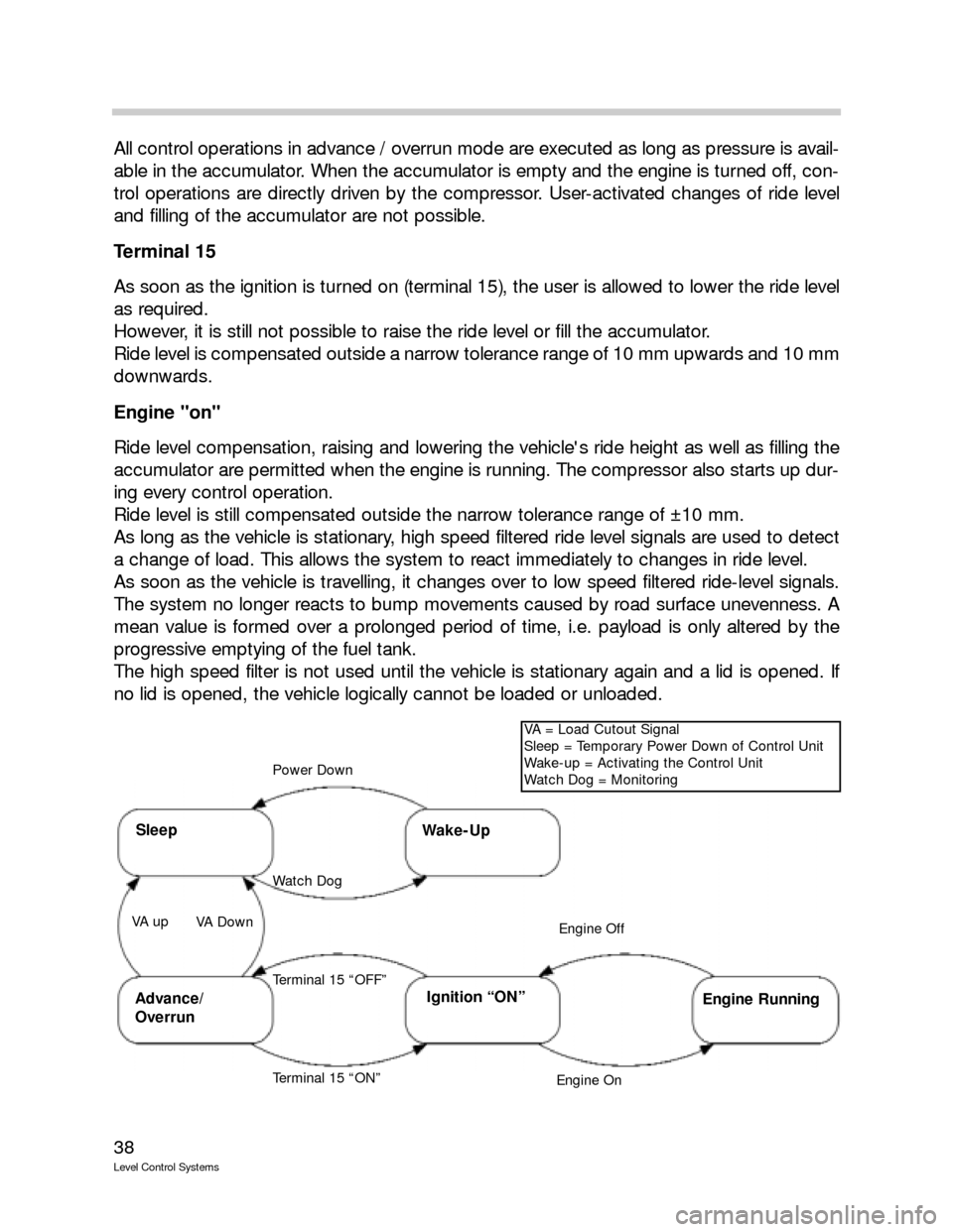
SleepWake-Up
Power Down
Watch Dog
Ignition “ON”Advance/
Overrun
VA = Load Cutout Signal
Sleep = Temporary Power Down of Control Unit
Wake-up = Activating the Control Unit
Watch Dog = Monitoring
Engine Off
Engine On
Engine Running
Terminal 15 “ON” VA up
VA Down
Terminal 15 “OFF”
Page 46 of 57
46
Level Control Systems
Ride Height Sensor
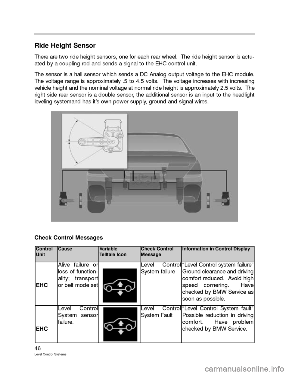
There are two ride height sensors, one for each rear wheel. The ride height sensor is actu-
ated by a coupling rod and sends a signal to the EHC control unit.
The sensor is a hall sensor which sends a DC Analog output voltage to the EHC module.
The voltage range is approximately .5 to 4.5 volts. The voltage increases with increasing
vehicle height and the nominal voltage at normal ride height is approximately 2.5 volts. The
right side rear sensor is a double sensor, the additional sensor is an input to the headlight
leveling systemand has it’s own power supply, ground and signal wires.
Check Control Messages
Control
UnitCauseVariable
Telltale IconCheck Control
MessageInformation in Control Display
EHC
Alive failure or
loss of function-
ality; transport
or belt mode setLevel Control
System failure“Level Control system failure”
Ground clearance and driving
comfort reduced. Avoid high
speed cornering. Have
checked by BMW Service as
soon as possible.
EHC
Level Control
System sensor
failure.Level Control
System Fault“Level Control System fault”
Possible reduction in driving
comfort. Have problem
checked by BMW Service.