rear entertainment BMW 760i 2005 E65 User Guide
[x] Cancel search | Manufacturer: BMW, Model Year: 2005, Model line: 760i, Model: BMW 760i 2005 E65Pages: 239, PDF Size: 8.03 MB
Page 55 of 239
Controls
53Reference
At a glance
Driving tips
Communications
Navigation
Entertainment
Mobility
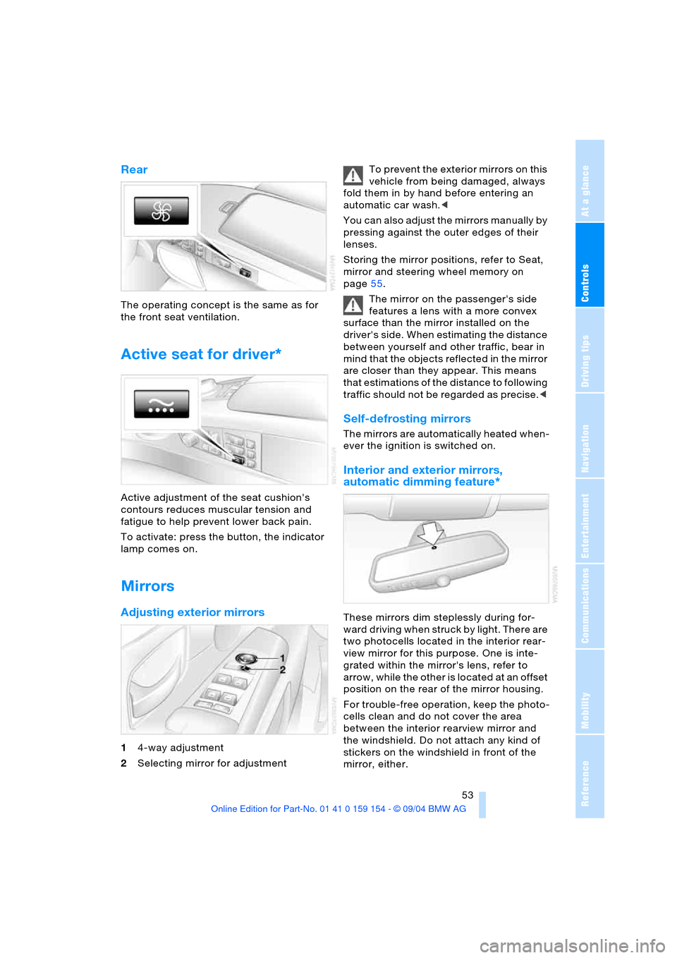
Rear
The operating concept is the same as for
the front seat ventilation.
Active seat for driver*
Active adjustment of the seat cushion's
contours reduces muscular tension and
fatigue to help prevent lower back pain.
To activate: press the button, the indicator
lamp comes on.
Mirrors
Adjusting exterior mirrors
14-way adjustment
2Selecting mirror for adjustment To prevent the exterior mirrors on this
vehicle from being damaged, always
fold them in by hand before entering an
automatic car wash.<
You can also adjust the mirrors manually by
pressing against the outer edges of their
lenses.
Storing the mirror positions, refer to Seat,
mirror and steering wheel memory on
page55.
The mirror on the passenger's side
features a lens with a more convex
surface than the mirror installed on the
driver's side. When estimating the distance
between yourself and other traffic, bear in
mind that the objects reflected in the mirror
are closer than they appear. This means
that estimations of the distance to following
traffic should not be regarded as precise.<
Self-defrosting mirrors
The mirrors are automatically heated when-
ever the ignition is switched on.
Interior and exterior mirrors,
automatic dimming feature*
These mirrors dim steplessly during for-
ward driving when struck by light. There are
two photocells located in the interior rear-
view mirror for this purpose. One is inte-
grated within the mirror's lens, refer to
arrow, while the other is located at an offset
position on the rear of the mirror housing.
For trouble-free operation, keep the photo-
cells clean and do not cover the area
between the interior rearview mirror and
the windshield. Do not attach any kind of
stickers on the windshield in front of the
mirror, either.
Page 57 of 239
Controls
55Reference
At a glance
Driving tips
Communications
Navigation
Entertainment
Mobility
Hold refer to Automatic Hold on
page65.
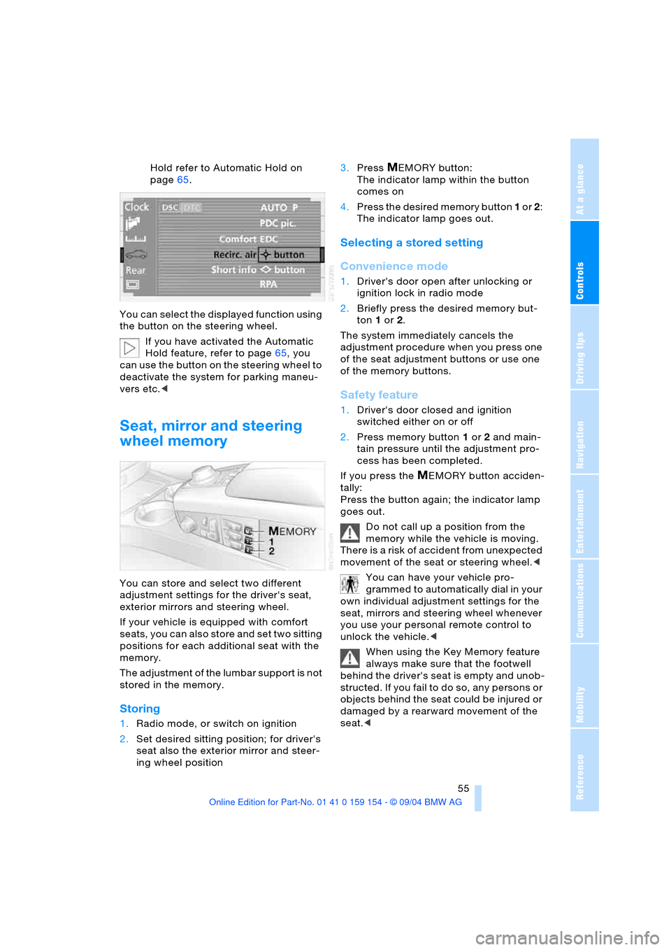
You can select the displayed function using
the button on the steering wheel.
If you have activated the Automatic
Hold feature, refer to page65, you
can use the button on the steering wheel to
deactivate the system for parking maneu-
vers etc.<
Seat, mirror and steering
wheel memory
You can store and select two different
adjustment settings for the driver's seat,
exterior mirrors and steering wheel.
If your vehicle is equipped with comfort
seats, you can also store and set two sitting
positions for each additional seat with the
memory.
The adjustment of the lumbar support is not
stored in the memory.
Storing
1.Radio mode, or switch on ignition
2.Set desired sitting position; for driver's
seat also the exterior mirror and steer-
ing wheel position 3.Press
MEMORY button:
The indicator lamp within the button
comes on
4.Press the desired memory button 1 or 2:
The indicator lamp goes out.
Selecting a stored setting
Convenience mode
1.Driver's door open after unlocking or
ignition lock in radio mode
2.Briefly press the desired memory but-
ton 1 or2.
The system immediately cancels the
adjustment procedure when you press one
of the seat adjustment buttons or use one
of the memory buttons.
Safety feature
1.Driver's door closed and ignition
switched either on or off
2.Press memory button 1 or2 and main-
tain pressure until the adjustment pro-
cess has been completed.
If you press the
MEMORY button acciden-
tally:
Press the button again; the indicator lamp
goes out.
Do not call up a position from the
memory while the vehicle is moving.
There is a risk of accident from unexpected
movement of the seat or steering wheel.<
You can have your vehicle pro-
grammed to automatically dial in your
own individual adjustment settings for the
seat, mirrors and steering wheel whenever
you use your personal remote control to
unlock the vehicle.<
When using the Key Memory feature
always make sure that the footwell
behind the driver's seat is empty and unob-
structed. If you fail to do so, any persons or
objects behind the seat could be injured or
damaged by a rearward movement of the
seat.<
Page 61 of 239
Controls
59Reference
At a glance
Driving tips
Communications
Navigation
Entertainment
Mobility
child restraint system and the affected
vehicle safety-belt system checked and,
if necessary, replaced. Only have corre-
sponding work carried out by a BMW cen-
ter or a workshop that uses personnel
trained in accordance with BMW require-
ments.<
Commercially-available child-restraint sys-
tems are designed to be secured with a lap
belt or with the lap belt portion of a combi-
nation lap/shoulder belt. Improperly or
inadequately installed restraint systems
can increase the risk of injury to children.
Always read and follow the instructions that
come with the system.
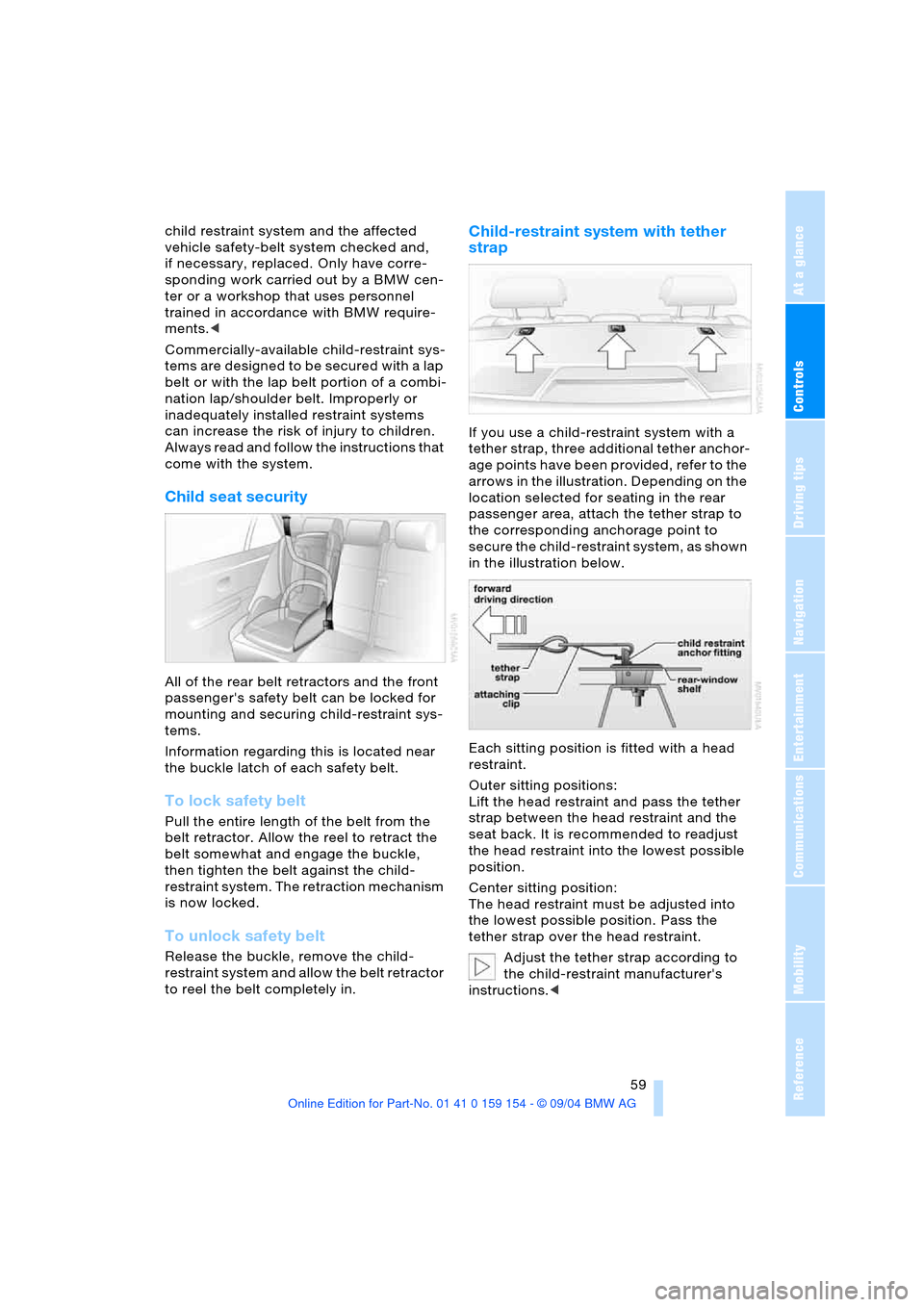
Child seat security
All of the rear belt retractors and the front
passenger's safety belt can be locked for
mounting and securing child-restraint sys-
tems.
Information regarding this is located near
the buckle latch of each safety belt.
To lock safety belt
Pull the entire length of the belt from the
belt retractor. Allow the reel to retract the
belt somewhat and engage the buckle,
then tighten the belt against the child-
restraint system. The retraction mechanism
is now locked.
To unlock safety belt
Release the buckle, remove the child-
restraint system and allow the belt retractor
to reel the belt completely in.
Child-restraint system with tether
strap
If you use a child-restraint system with a
tether strap, three additional tether anchor-
age points have been provided, refer to the
arrows in the illustration. Depending on the
location selected for seating in the rear
passenger area, attach the tether strap to
the corresponding anchorage point to
secure the child-restraint system, as shown
in the illustration below.
Each sitting position is fitted with a head
restraint.
Outer sitting positions:
Lift the head restraint and pass the tether
strap between the head restraint and the
seat back. It is recommended to readjust
the head restraint into the lowest possible
position.
Center sitting position:
The head restraint must be adjusted into
the lowest possible position. Pass the
tether strap over the head restraint.
Adjust the tether strap according to
the child-restraint manufacturer's
instructions.<
Page 63 of 239
Controls
61Reference
At a glance
Driving tips
Communications
Navigation
Entertainment
Mobility
The door can now be opened from the out-
side only.
Safety switch for power windows
and rear seats
If the vehicle is equipped with power seats
in the rear, return these to their standard
adjustment setting before using a child-
restraint system, refer to page49.
Always press the safety switch for the
power windows, refer to page44, when
children are in the rear of the vehicle.
This switch also disables the power rear
seat adjustment.
Incorrect or unsupervised adjustment
of the power seats in the rear could
lead to injuries or damage to the child-
restraint system.<
Page 69 of 239
Controls
67Reference
At a glance
Driving tips
Communications
Navigation
Entertainment
Mobility
What you will need
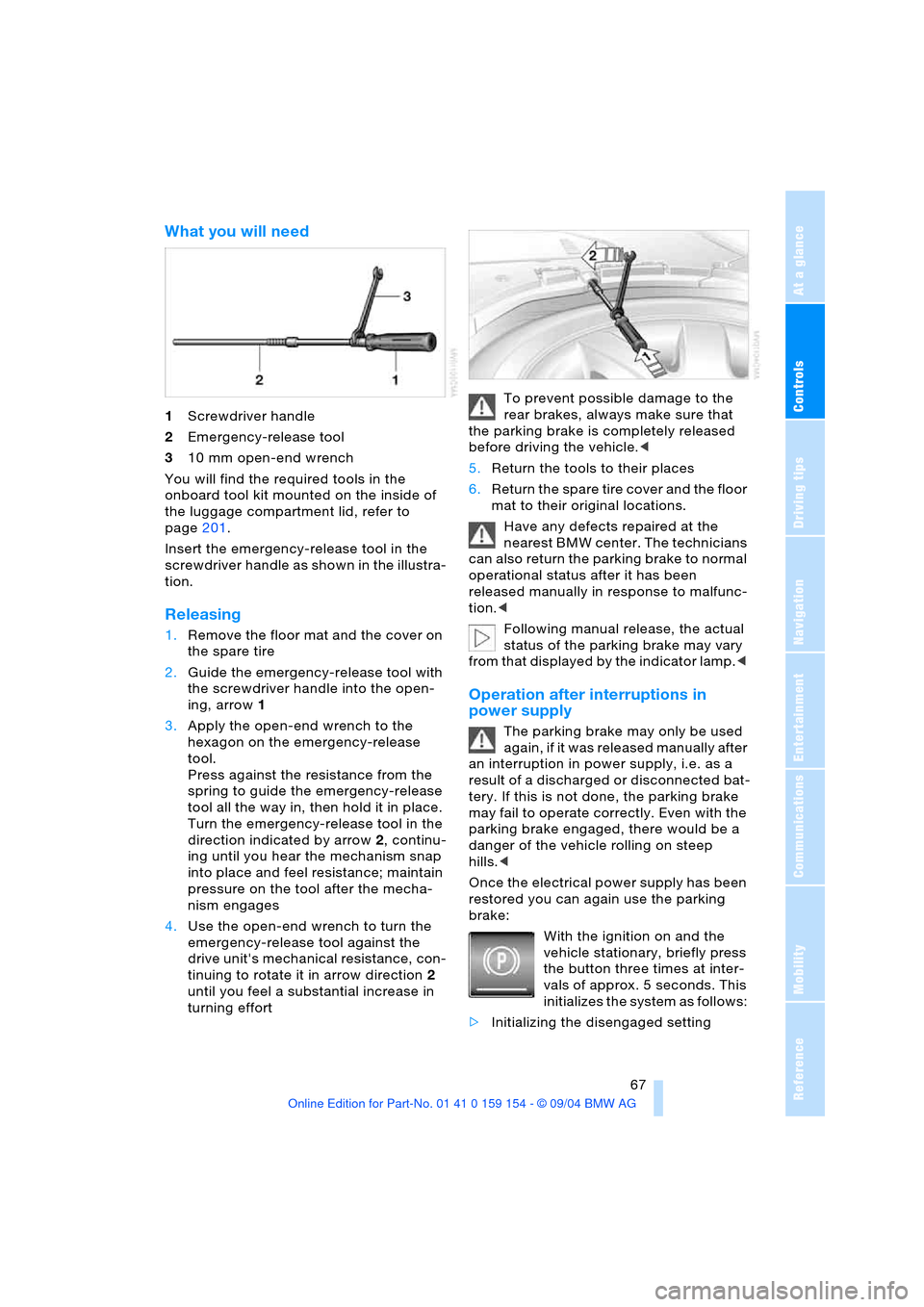
1Screwdriver handle
2Emergency-release tool
310 mm open-end wrench
You will find the required tools in the
onboard tool kit mounted on the inside of
the luggage compartment lid, refer to
page201.
Insert the emergency-release tool in the
screwdriver handle as shown in the illustra-
tion.
Releasing
1.Remove the floor mat and the cover on
the spare tire
2.Guide the emergency-release tool with
the screwdriver handle into the open-
ing, arrow1
3.Apply the open-end wrench to the
hexagon on the emergency-release
tool.
Press against the resistance from the
spring to guide the emergency-release
tool all the way in, then hold it in place.
Turn the emergency-release tool in the
direction indicated by arrow2, continu-
ing until you hear the mechanism snap
into place and feel resistance; maintain
pressure on the tool after the mecha-
nism engages
4.Use the open-end wrench to turn the
emergency-release tool against the
drive unit's mechanical resistance, con-
tinuing to rotate it in arrow direction2
until you feel a substantial increase in
turning effortTo prevent possible damage to the
rear brakes, always make sure that
the parking brake is completely released
before driving the vehicle.<
5.Return the tools to their places
6.Return the spare tire cover and the floor
mat to their original locations.
Have any defects repaired at the
nearest BMW center. The technicians
can also return the parking brake to normal
operational status after it has been
released manually in response to malfunc-
tion.<
Following manual release, the actual
status of the parking brake may vary
from that displayed by the indicator lamp.<
Operation after interruptions in
power supply
The parking brake may only be used
again, if it was released manually after
an interruption in power supply, i.e. as a
r esu lt o f a dis ch ar ged or d isc on ne cte d bat -
tery. If this is not done, the parking brake
may fail to operate correctly. Even with the
parking brake engaged, there would be a
danger of the vehicle rolling on steep
hills.<
Once the electrical power supply has been
restored you can again use the parking
brake:
With the ignition on and the
vehicle stationary, briefly press
the button three times at inter-
vals of approx. 5 seconds. This
initializes the system as follows:
>Initializing the disengaged setting
Page 71 of 239
Controls
69Reference
At a glance
Driving tips
Communications
Navigation
Entertainment
Mobility
>Park P:
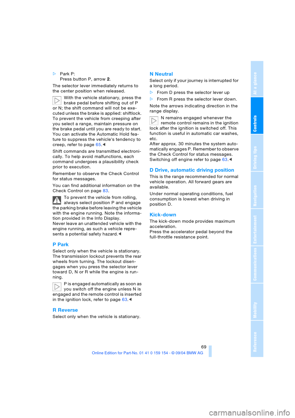
Press button P, arrow2.
The selector lever immediately returns to
the center position when released.
With the vehicle stationary, press the
brake pedal before shifting out of P
or N; the shift command will not be exe-
cuted unless the brake is applied: shiftlock.
To prevent the vehicle from creeping after
you select a range, maintain pressure on
the brake pedal until you are ready to start.
You can activate the Automatic Hold fea-
ture to suppress the vehicle's tendency to
creep, refer to page65.<
Shift commands are transmitted electroni-
cally. To help avoid malfunctions, each
command undergoes a plausibility check
prior to execution.
Remember to observe the Check Control
for status messages.
You can find additional information on the
Check Control on page83.
To prevent the vehicle from rolling,
always select position P and engage
the parking brake before leaving the vehicle
with the engine running. Note the informa-
tion provided in the Info Display.
Never leave an unattended vehicle with the
engine running, as such a vehicle repre-
sents a potential safety hazard.<
P Park
Select only when the vehicle is stationary.
The transmission lockout prevents the rear
wheels from turning. The lockout disen-
gages when you press the selector lever
toward D, N or R while the engine is run-
ning.
P is engaged automatically as soon as
you switch off the engine unless N is
engaged and the remote control is inserted
in the ignition lock, refer to page63.<
R Reverse
Select only when the vehicle is stationary.
N Neutral
Select only if your journey is interrupted for
a long period.
>From D press the selector lever up
>From R press the selector lever down.
Note the arrows indicating direction in the
range display.
N remains engaged whenever the
remote control remains in the ignition
lock after the ignition is switched off. This
function is useful in automatic car washes,
etc.
After approx. 30 minutes the system auto-
matically engages P. Remember to observe
the Check Control for status messages.
Switching off engine refer to page63.<
D Drive, automatic driving position
This is the range recommended for normal
vehicle operation. All forward gears are
available.
Under normal operating conditions, fuel
consumption is lowest when driving in
position D.
Kick-down
The kick-down mode provides maximum
acceleration.
Press the accelerator pedal beyond the
full-throttle resistance point.
Page 93 of 239
Controls
91Reference
At a glance
Driving tips
Communications
Navigation
Entertainment
Mobility
Technology for comfort, convenience
and safety
PDC Park Distance Control*
The concept
The PDC assists you when you are parking.
Signal tones indicate the current distance
to an object behind or in front of your vehi-
cle. Four ultrasonic sensors in both the
bumpers monitor the distance to the near-
est object. The sensors at the front and at
the two rear corners have a range of
approx. 2 ft/60 cm; the rear middle sensors
have approx. 5 ft/1.50 m.
PDC is a parking aid that can indicate
objects when they are approached
slowly, as is usually the case when parking.
Avoid approaching an object at high speed,
as otherwise the physical circumstances
would mean that the system warning was
too late.<
Automatic function
Whenever the ignition is on the system
automatically assumes operational status
after a few seconds each time you engage
the transmission position R.
Wait this short period before revers-
ing.<
Switching on manually
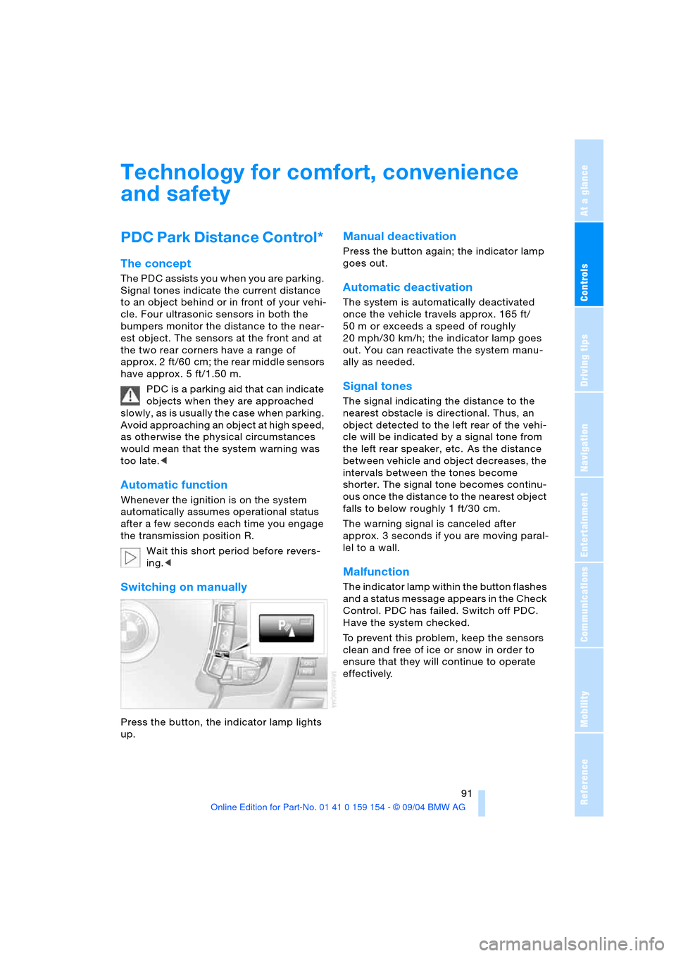
Press the button, the indicator lamp lights
up.
Manual deactivation
Press the button again; the indicator lamp
goes out.
Automatic deactivation
The system is automatically deactivated
once the vehicle travels approx. 165 ft/
50 m or exceeds a speed of roughly
20 mph/30 km/h; the indicator lamp goes
out. You can reactivate the system manu-
ally as needed.
Signal tones
The signal indicating the distance to the
nearest obstacle is directional. Thus, an
object detected to the left rear of the vehi-
cle will be indicated by a signal tone from
the left rear speaker, etc. As the distance
between vehicle and object decreases, the
intervals between the tones become
shorter. The signal tone becomes continu-
ous once the distance to the nearest object
falls to below roughly 1 ft/30 cm.
The warning signal is canceled after
approx. 3 seconds if you are moving paral-
lel to a wall.
Malfunction
The indicator lamp within the button flashes
and a status message appears in the Check
Control. PDC has failed. Switch off PDC.
Have the system checked.
To prevent this problem, keep the sensors
clean and free of ice or snow in order to
ensure that they will continue to operate
effectively.
Page 95 of 239
Controls
93Reference
At a glance
Driving tips
Communications
Navigation
Entertainment
Mobility
EBV Electronic brake-force
distribution
EBV controls the brake system's applica-
tion pressure at the rear wheels to ensure
stable deceleration.
DSC Dynamic Stability Control
The system optimizes vehicle stability dur-
ing acceleration and when starting from a
full stop, as well as optimizing traction.
The system recognizes any tendency for
the vehicle to assume an unstable attitude
such as oversteer or understeer; it then
counteracts this tendency with a combina-
tion of graduated reductions in engine
torque and selective braking intervention at
individual wheels. DSC provides optimized
stability within the limits defined by the
laws of physics.
The DSC is operational every time you start
the engine. DSC contains the functions
DTC Dynamic Traction Control and DBC
Dynamic Brake Control.
Indicator lamp
The indicator lamp goes out shortly
after the engine starts.
The indicator lamp flashes:
DSC controls the drive and braking forces.
The indicator lamp stays lit:
DSC has been switched off using the Con-
trol Center.
Activating DTC Dynamic Traction
Control
In particular driving situations, in deep
snow, for example, DTC ensures the maxi-
mum forward momentum. The gain in for-
ward momentum in these situations
involves a reduction in vehicle stability.
DTC is active up to 45 mph/70 km/h.You may find it useful to briefly activate
DTC under the following special circum-
stances:
>When rocking the vehicle and starting
off in deep snow or on loose road sur-
faces
>When ascending snow-covered hills,
and when driving in deep or on hard-
packed snow
>When driving with snow chains.
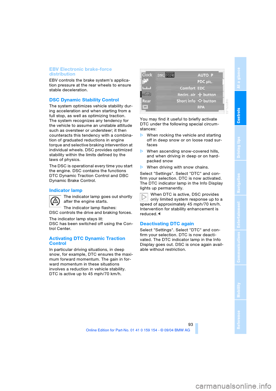
Select "Settings". Select "DTC" and con-
firm your selection. DTC is now activated.
The DTC indicator lamp in the Info Display
lights up permanently.
When DTC is active, DSC provides
only limited system response up to a
speed of approximately 45 mph/70 km/h.
Intervention for stability enhancement is
reduced.<
Deactivating DTC again
Select "Settings". Select "DTC" and con-
firm your selection. DTC is now deacti-
vated. The DTC indicator lamp in the Info
Display goes out. DSC is once again avail-
able without restriction.
Page 97 of 239
Controls
95Reference
At a glance
Driving tips
Communications
Navigation
Entertainment
Mobility
Have the system checked as soon as pos-
sible.
Display of the previously described
malfunction on Canadian models.
Dynamic Drive
The concept
Dynamic Drive minimizes body roll and
optimizes vehicle stability during cornering
and evasive maneuvers.
Active stabilizers at the front and rear axles
form the basis for Dynamic Drive. Suspen-
sion compliance adapts to suit driving con-
ditions, varying from performance-oriented
during cornering to smooth and comfort-
oriented when the vehicle is proceeding in
a straight line.
The system assumes operational status
each time you start the engine.
Driving with Dynamic Drive
During vehicle operation, the system con-
tinuously runs through closed-loop control
cycles lasting only fractions of a second.
Malfunction
The warning lamp lights up, accom-
panied by a status message in the
Check Control. Please take note of
the additional information on the Control
Display. A malfunction has occurred in the
system. Have the system checked as soon
as possible.
If the Dynamic Drive system switches
off in response to malfunction, please
remember to adapt your speed accord-
ingly, especially in curves.
The suspension will be noticeably softer
and the vehicle will display a greater ten-
dency to tilt during cornering and in cross-
winds.
If a Check Control message stating that you
should stop appears in addition to the red
symbol, stop immediately and switch off
the engine. In this case the oil level in the
reservoir may have dropped below the min-imum, possibly owing to a leak in the
hydraulic system.
Please observe the additional instructions
provided on the Control Display.<
EDC Electronic Damping
Control*
The suspension responds to changes in
factors such as road surface, or operating
conditions such as steering and braking, by
adapting to the new conditions within frac-
tions of a second.
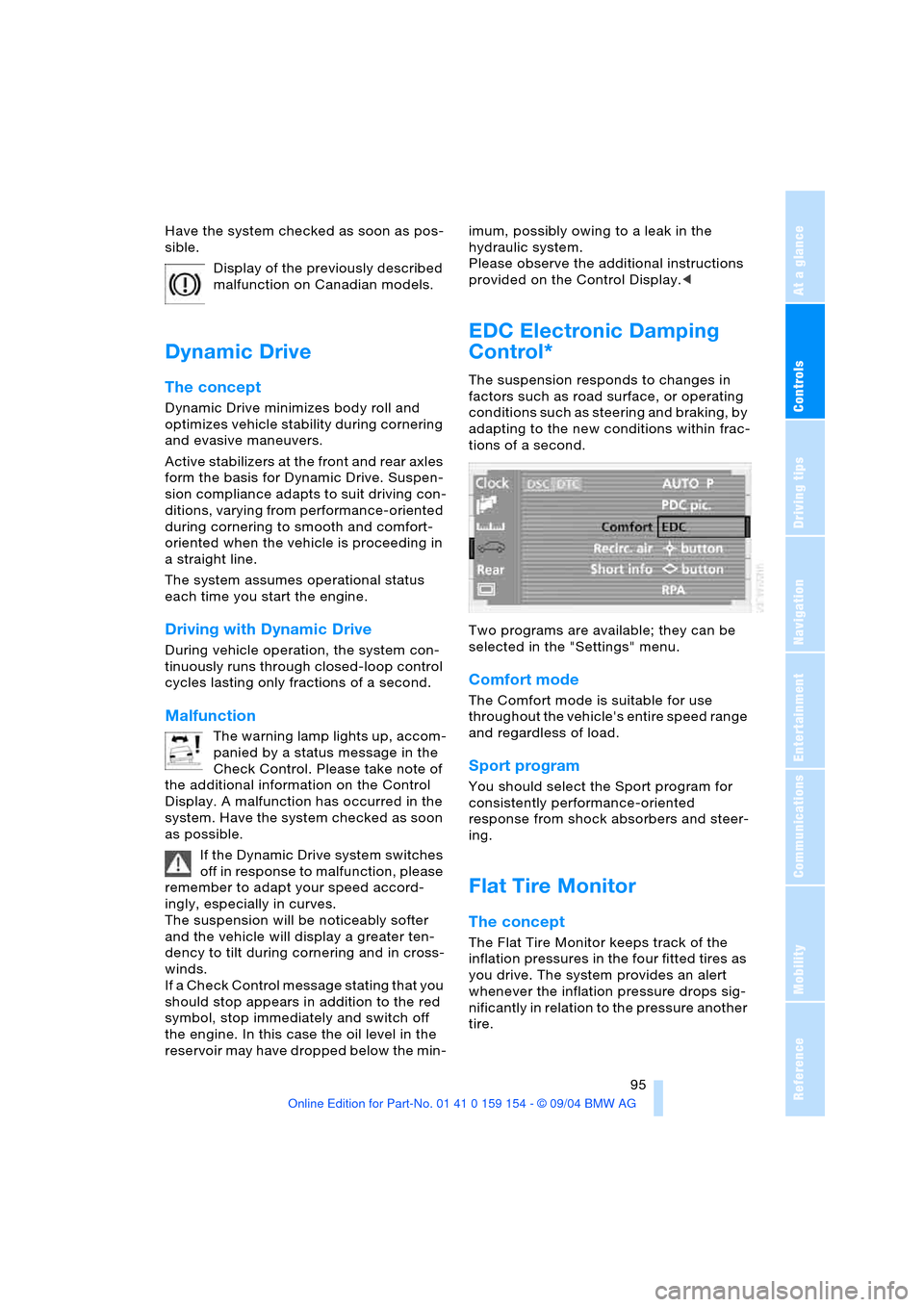
Two programs are available; they can be
selected in the "Settings" menu.
Comfort mode
The Comfort mode is suitable for use
throughout the vehicle's entire speed range
and regardless of load.
Sport program
You should select the Sport program for
consistently performance-oriented
response from shock absorbers and steer-
ing.
Flat Tire Monitor
The concept
The Flat Tire Monitor keeps track of the
inflation pressures in the four fitted tires as
you drive. The system provides an alert
whenever the inflation pressure drops sig-
nificantly in relation to the pressure another
tire.
Page 99 of 239
Controls
97Reference
At a glance
Driving tips
Communications
Navigation
Entertainment
Mobility
Vehicles with run-flat tires:
1.Cautiously reduce the vehicle speed to
below 50 mph/80 km/h. Avoid sudden
braking and steering maneuvers. Do not
exceed a vehicle speed of 50 mph/80
km/h
Due to the reinforcement on the
side walls of the run-flat tires,
inflation pressure loss can not usually
be recognized from the outside, refer to
Run-flat tires on page206.<
2.To continue driving, comply with the
instructions for driving with damaged
tires on page206.
Malfunction
The indicator lamp lights up yellow,
accompanied by a status message
in the Check Control. The Flat Tire
Monitor has malfunctioned or failed. Have
the system checked as soon as possible.
Self-leveling suspension*
Malfunction
A Check Control message appear-
ing together with this symbol indi-
cates a malfunction in the self-level-
ing suspension. Please take note of the
additional information on the Control Dis-
play.
Stop and inspect the vehicle. If the rear of
the vehicle is visibly lower than the front,
possibly accompanied by a tilt noticeable
when you compare the left rear with the
right rear, please respond by immediately
proceeding to the nearest BMW center.
Drive with appropriate caution in the mean-
time. The vehicle has reduced ground
clearance and driving comfort may be
noticeably reduced. Even if the attitude of
the vehicle is normal, you should consult
the nearest BMW center if the warning
lamp indicates a system fault.
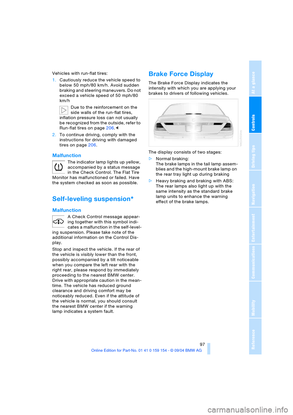
Brake Force Display
The Brake Force Display indicates the
intensity with which you are applying your
brakes to drivers of following vehicles.
The display consists of two stages:
>Normal braking:
The brake lamps in the tail lamp assem-
blies and the high-mount brake lamp on
the rear tray light up during braking
>Heavy braking and braking with ABS:
The rear lamps also light up with the
same intensity as the standard brake
lamp units to enhance the warning
effect of the brake lamps.