engine BMW ACTIVE HYBRID 7 2013 F04 Owner's Guide
[x] Cancel search | Manufacturer: BMW, Model Year: 2013, Model line: ACTIVE HYBRID 7, Model: BMW ACTIVE HYBRID 7 2013 F04Pages: 253, PDF Size: 5.01 MB
Page 85 of 253

After the wipers are folded back down, the
wiper system must be reactivated.
Fold the wipers back down
Before switching the ignition on, fold the
wipers back down to the windshield; other‐
wise, the wipers may become damaged when
they are switched on.◀1.Switch on the ignition.2.Press the wiper levers down. The wipers
move to their resting position and are
ready for operation.
Washer fluid
General information Antifreeze for washer fluid
Antifreeze is flammable and can cause
injury if it is used incorrectly.
Therefore, keep it away from sources of igni‐
tion.
Only keep it in the closed original container
and inaccessible to children.
Follow the notes and instructions on the con‐
tainer.
United States: The washer fluid mixture ratio is
regulated by the U.S. EPA and many individual
states; do not exceed the allowable washer
fluid dilution ratios limits that apply. Follow the
usage instructions on the washer fluid con‐
tainer. Use BMW’s Windshield Washer Con‐
centrate or the equivalent.◀
Washer fluid reservoir Adding washer fluid
Only add washer fluid when the engine is
cool, and then close the cover completely to
avoid contact between the washer fluid and
hot engine parts.
Otherwise, there is the danger of fire and a risk
to personal safety if the fluid is spilled.◀
All washer nozzles are supplied from one res‐
ervoir.
Fill with a mixture of windshield washer con‐
centrate and tap water and – if required – with a
washer antifreeze, according to the manufac‐
turer's recommendations.
Mix the washer fluid before adding to maintain
the correct mixing ratio.
Do not add windshield washer concentrate and
antifreeze undiluted and do not fill with pure
water; this could damage the wiper system.
Do not mix window washer concentrates of dif‐
ferent manufacturers, because otherwise it can
result in clogging of the windshield washer
nozzles.
For the capacity, refer to technical data.
Automatic transmission with
Steptronic
Transmission positions
D Drive, automatic position
Position for normal vehicle operation. All for‐
ward gears are available.
R is Reverse
Select only when the vehicle is stationary.
N is NeutralUse in automatic car washes, for example. The
vehicle can roll.
Seite 81DrivingControls81
Online Edition for Part no. 01 40 2 909 774 - VI/13
Page 86 of 253
When the ignition is switched off, refer to
page 70, position P is engaged automatically.
P Park Select only when the vehicle is stationary. The
drive wheels are blocked.
P is engaged automatically:▷After deactivating drive readiness when the
vehicle is in radio ready state, refer to
page 70, or when the ignition is switched
off, refer to page 70, and when position R
or D is engaged.▷With the ignition is off, if position N is en‐
gaged.▷If the safety belt is unbuckled, the driver's
door is opened, and the brake pedal is not
pressed while the vehicle is stationary and
transmission position R or D is engaged.
Before exiting the vehicle, make sure that posi‐
tion P of the automatic transmission is en‐
gaged. Otherwise, the vehicle may begin to
roll.
Kickdown
Kickdown is used to achieve maximum driving
performance. Press on the gas pedal beyond
the resistance point at the full throttle position.
Engaging the transmission position
▷Transmission position P can only be disen‐
gaged if the engine is running and the
brake pedal is pressed.▷With the vehicle stationary, press on the
brake pedal before shifting out of P or N;
otherwise, the shift command will not be
executed: shift lock.
Depress the brake until you start
driving
To prevent the vehicle from creeping after
you select a driving position, maintain
pressure on the brake pedal until you are
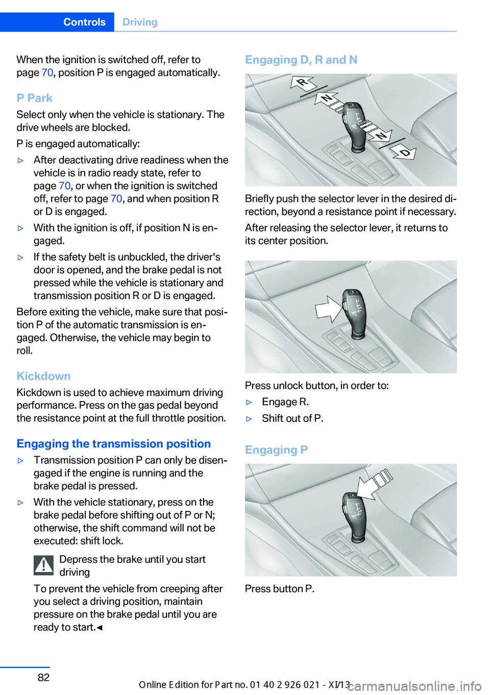
ready to start.◀Engaging D, R and N
Briefly push the selector lever in the desired di‐
rection, beyond a resistance point if necessary.
After releasing the selector lever, it returns to
its center position.
Press unlock button, in order to:
▷Engage R.▷Shift out of P.
Engaging P
Press button P.
Seite 82ControlsDriving82
Online Edition for Part no. 01 40 2 909 774 - VI/13
Page 87 of 253
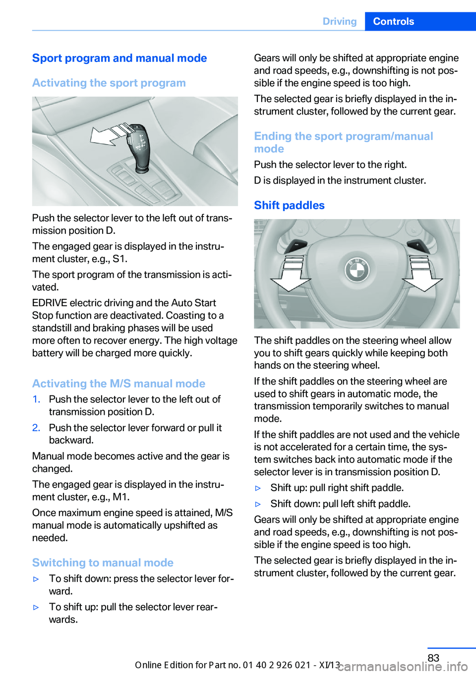
Sport program and manual mode
Activating the sport program
Push the selector lever to the left out of trans‐
mission position D.
The engaged gear is displayed in the instru‐
ment cluster, e.g., S1.
The sport program of the transmission is acti‐
vated.
EDRIVE electric driving and the Auto Start
Stop function are deactivated. Coasting to a
standstill and braking phases will be used
more often to recover energy. The high voltage
battery will be charged more quickly.
Activating the M/S manual mode
1.Push the selector lever to the left out of
transmission position D.2.Push the selector lever forward or pull it
backward.
Manual mode becomes active and the gear is
changed.
The engaged gear is displayed in the instru‐
ment cluster, e.g., M1.
Once maximum engine speed is attained, M/S
manual mode is automatically upshifted as
needed.
Switching to manual mode
▷To shift down: press the selector lever for‐
ward.▷To shift up: pull the selector lever rear‐
wards.Gears will only be shifted at appropriate engine
and road speeds, e.g., downshifting is not pos‐
sible if the engine speed is too high.
The selected gear is briefly displayed in the in‐
strument cluster, followed by the current gear.
Ending the sport program/manual
mode
Push the selector lever to the right.
D is displayed in the instrument cluster.
Shift paddles
The shift paddles on the steering wheel allow
you to shift gears quickly while keeping both
hands on the steering wheel.
If the shift paddles on the steering wheel are
used to shift gears in automatic mode, the
transmission temporarily switches to manual
mode.
If the shift paddles are not used and the vehicle
is not accelerated for a certain time, the sys‐
tem switches back into automatic mode if the
selector lever is in transmission position D.
▷Shift up: pull right shift paddle.▷Shift down: pull left shift paddle.
Gears will only be shifted at appropriate engine
and road speeds, e.g., downshifting is not pos‐
sible if the engine speed is too high.
The selected gear is briefly displayed in the in‐
strument cluster, followed by the current gear.
Seite 83DrivingControls83
Online Edition for Part no. 01 40 2 909 774 - VI/13
Page 90 of 253
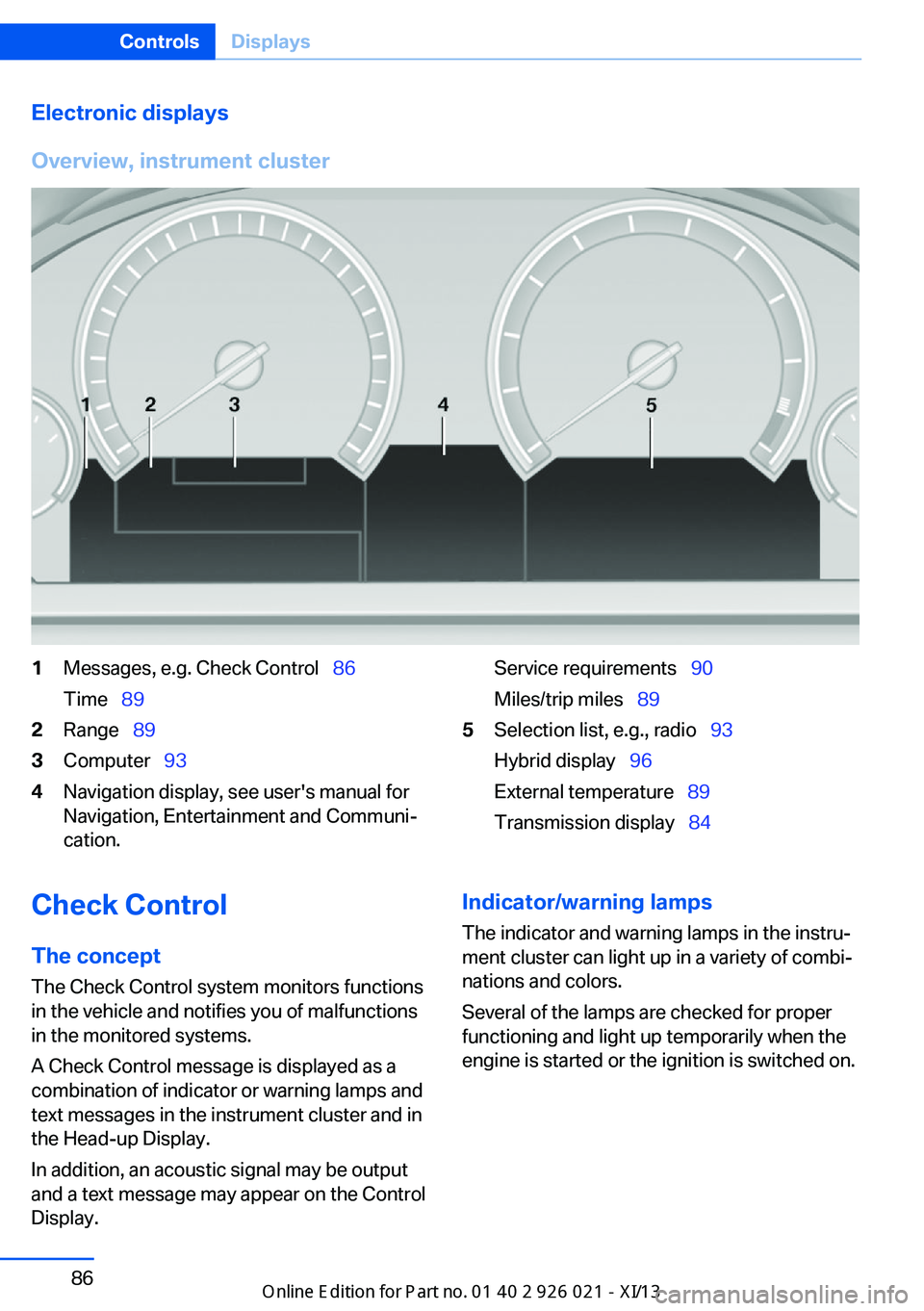
Electronic displays
Overview, instrument cluster1Messages, e.g. Check Control 86
Time 892Range 893Computer 934Navigation display, see user's manual for
Navigation, Entertainment and Communi‐
cation.Service requirements 90
Miles/trip miles 895Selection list, e.g., radio 93
Hybrid display 96
External temperature 89
Transmission display 84Check Control
The concept The Check Control system monitors functions
in the vehicle and notifies you of malfunctions
in the monitored systems.
A Check Control message is displayed as a
combination of indicator or warning lamps and
text messages in the instrument cluster and in
the Head-up Display.
In addition, an acoustic signal may be output
and a text message may appear on the Control Display.Indicator/warning lamps
The indicator and warning lamps in the instru‐
ment cluster can light up in a variety of combi‐
nations and colors.
Several of the lamps are checked for proper
functioning and light up temporarily when the
engine is started or the ignition is switched on.Seite 86ControlsDisplays86
Online Edition for Part no. 01 40 2 909 774 - VI/13
Page 91 of 253
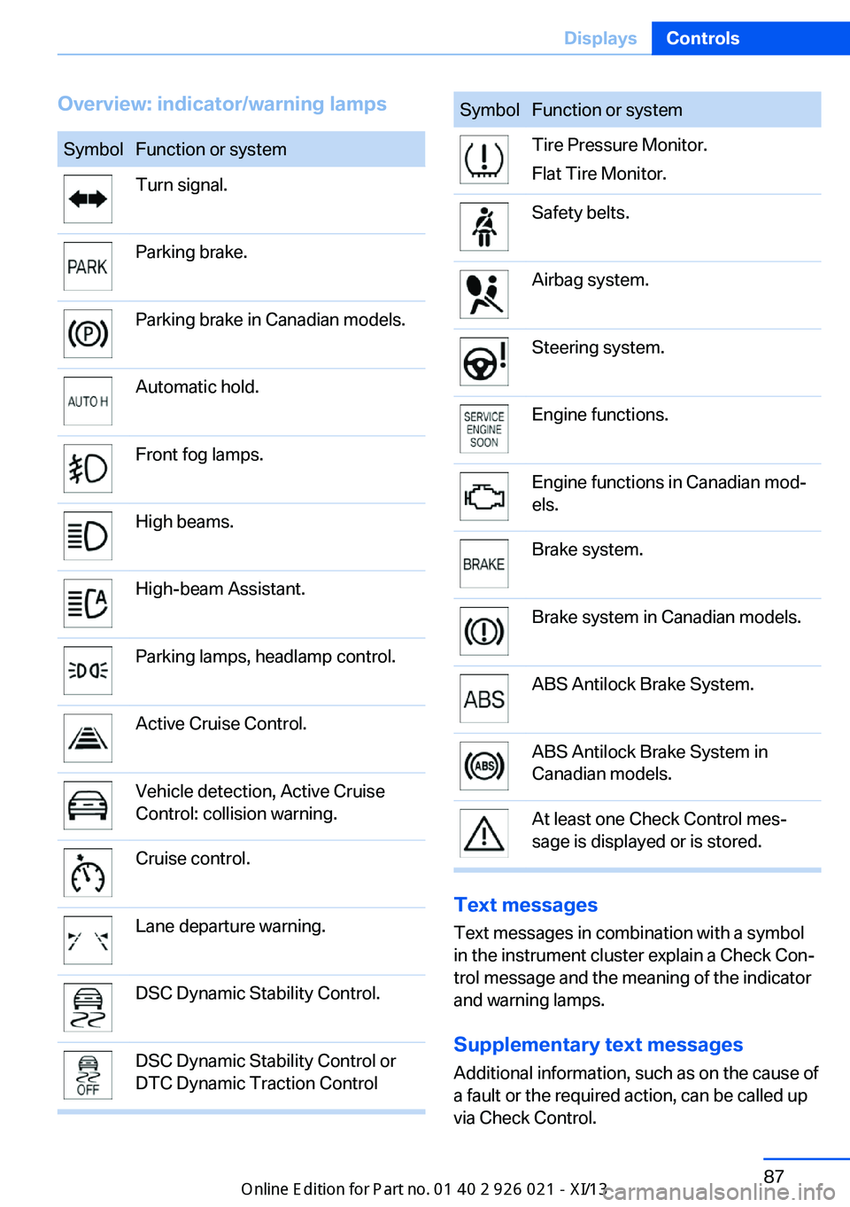
Overview: indicator/warning lampsSymbolFunction or systemTurn signal.Parking brake.Parking brake in Canadian models.Automatic hold.Front fog lamps.High beams.High-beam Assistant.Parking lamps, headlamp control.Active Cruise Control.Vehicle detection, Active Cruise
Control: collision warning.Cruise control.Lane departure warning.DSC Dynamic Stability Control.DSC Dynamic Stability Control or
DTC Dynamic Traction ControlSymbolFunction or systemTire Pressure Monitor.
Flat Tire Monitor.Safety belts.Airbag system.Steering system.Engine functions.Engine functions in Canadian mod‐
els.Brake system.Brake system in Canadian models.ABS Antilock Brake System.ABS Antilock Brake System in
Canadian models.At least one Check Control mes‐
sage is displayed or is stored.
Text messages
Text messages in combination with a symbol
in the instrument cluster explain a Check Con‐ trol message and the meaning of the indicator
and warning lamps.
Supplementary text messages
Additional information, such as on the cause of
a fault or the required action, can be called up
via Check Control.
Seite 87DisplaysControls87
Online Edition for Part no. 01 40 2 909 774 - VI/13
Page 92 of 253
The supplementary text of urgent messages is
automatically displayed on the Control Display.
Symbols
Depending on the Check Control message, the
following functions can be selected.▷ "Owner's Manual"
Display additional information about the
Check Control message in the Integrated
Owner's Manual.▷ "Service request"
Contact the service partner.▷ "Roadside Assistance"
Contact Roadside Assistance.
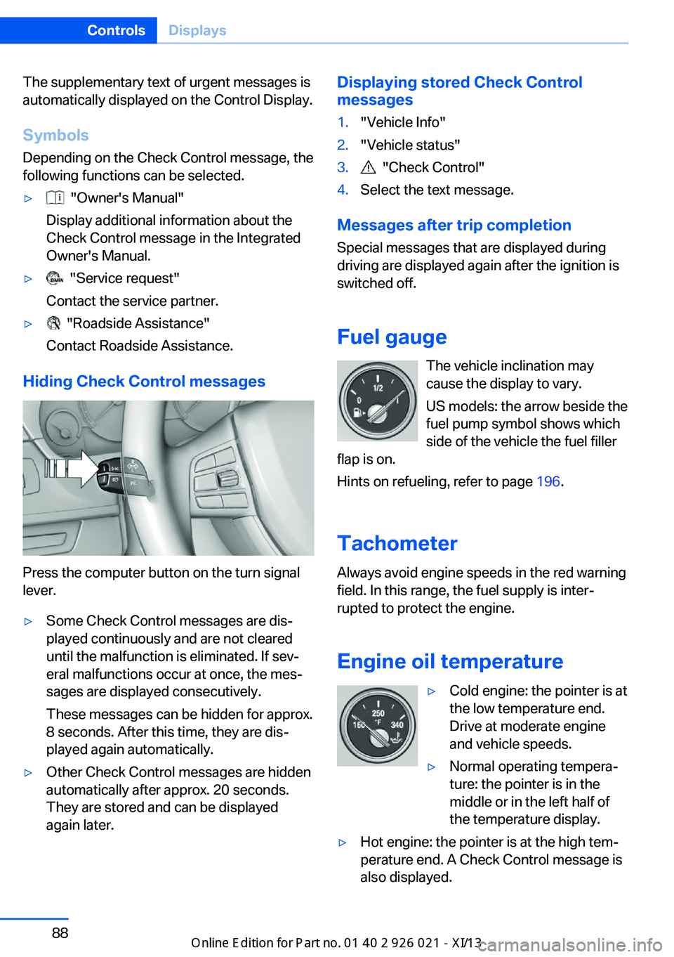
Hiding Check Control messages
Press the computer button on the turn signal
lever.
▷Some Check Control messages are dis‐
played continuously and are not cleared
until the malfunction is eliminated. If sev‐
eral malfunctions occur at once, the mes‐
sages are displayed consecutively.
These messages can be hidden for approx.
8 seconds. After this time, they are dis‐
played again automatically.▷Other Check Control messages are hidden
automatically after approx. 20 seconds.
They are stored and can be displayed
again later.Displaying stored Check Control
messages1."Vehicle Info"2."Vehicle status"3. "Check Control"4.Select the text message.
Messages after trip completion
Special messages that are displayed during
driving are displayed again after the ignition is
switched off.
Fuel gauge The vehicle inclination may
cause the display to vary.
US models: the arrow beside the
fuel pump symbol shows which
side of the vehicle the fuel filler
flap is on.
Hints on refueling, refer to page 196.
Tachometer
Always avoid engine speeds in the red warning
field. In this range, the fuel supply is inter‐
rupted to protect the engine.
Engine oil temperature
▷Cold engine: the pointer is at
the low temperature end.
Drive at moderate engine
and vehicle speeds.▷Normal operating tempera‐
ture: the pointer is in the
middle or in the left half of
the temperature display.▷Hot engine: the pointer is at the high tem‐
perature end. A Check Control message is
also displayed.Seite 88ControlsDisplays88
Online Edition for Part no. 01 40 2 909 774 - VI/13
Page 93 of 253
Coolant temperatureIf the coolant along with the engine becomes
too hot, a Check Control message is displayed.
Check the coolant level, refer to page 210.
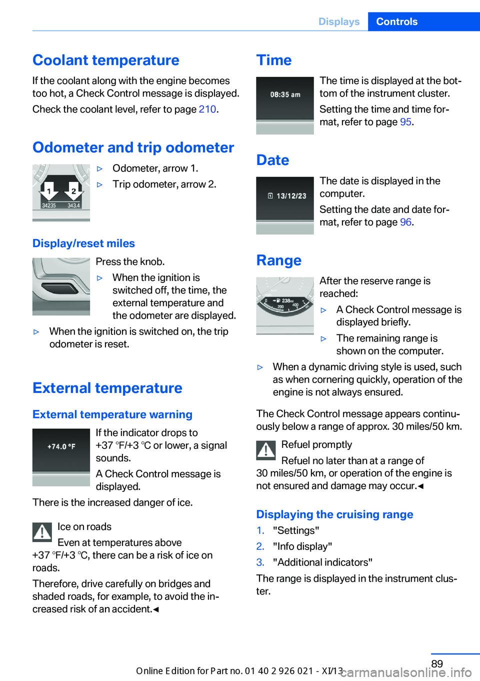
Odometer and trip odometer▷Odometer, arrow 1.▷Trip odometer, arrow 2.
Display/reset miles Press the knob.
▷When the ignition is
switched off, the time, the
external temperature and
the odometer are displayed.▷When the ignition is switched on, the trip
odometer is reset.
External temperature
External temperature warning If the indicator drops to
+37 ℉/+3 ℃ or lower, a signal
sounds.
A Check Control message is displayed.
There is the increased danger of ice.
Ice on roads
Even at temperatures above
+37 ℉/+3 ℃, there can be a risk of ice on
roads.
Therefore, drive carefully on bridges and
shaded roads, for example, to avoid the in‐
creased risk of an accident.◀
Time
The time is displayed at the bot‐
tom of the instrument cluster.
Setting the time and time for‐
mat, refer to page 95.
Date The date is displayed in the
computer.
Setting the date and date for‐
mat, refer to page 96.
Range After the reserve range isreached:▷A Check Control message is
displayed briefly.▷The remaining range is
shown on the computer.▷When a dynamic driving style is used, such
as when cornering quickly, operation of the
engine is not always ensured.
The Check Control message appears continu‐
ously below a range of approx. 30 miles/50 km.
Refuel promptly
Refuel no later than at a range of
30 miles/50 km, or operation of the engine is
not ensured and damage may occur.◀
Displaying the cruising range
1."Settings"2."Info display"3."Additional indicators"
The range is displayed in the instrument clus‐
ter.
Seite 89DisplaysControls89
Online Edition for Part no. 01 40 2 909 774 - VI/13
Page 98 of 253
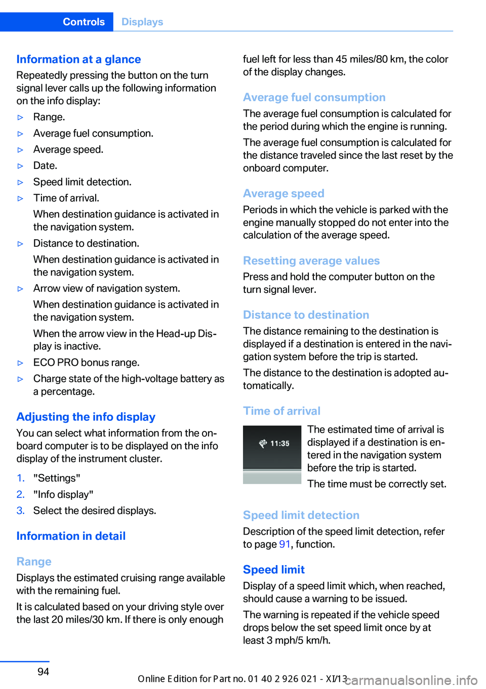
Information at a glanceRepeatedly pressing the button on the turn
signal lever calls up the following information
on the info display:▷Range.▷Average fuel consumption.▷Average speed.▷Date.▷Speed limit detection.▷Time of arrival.
When destination guidance is activated in
the navigation system.▷Distance to destination.
When destination guidance is activated in
the navigation system.▷Arrow view of navigation system.
When destination guidance is activated in
the navigation system.
When the arrow view in the Head-up Dis‐
play is inactive.▷ECO PRO bonus range.▷Charge state of the high-voltage battery as
a percentage.
Adjusting the info display
You can select what information from the on‐
board computer is to be displayed on the info
display of the instrument cluster.
1."Settings"2."Info display"3.Select the desired displays.
Information in detail
Range
Displays the estimated cruising range available
with the remaining fuel.
It is calculated based on your driving style over
the last 20 miles/30 km. If there is only enough
fuel left for less than 45 miles/80 km, the color
of the display changes.
Average fuel consumption
The average fuel consumption is calculated for
the period during which the engine is running.
The average fuel consumption is calculated for
the distance traveled since the last reset by the
onboard computer.
Average speed
Periods in which the vehicle is parked with the
engine manually stopped do not enter into the
calculation of the average speed.
Resetting average values
Press and hold the computer button on the
turn signal lever.
Distance to destination
The distance remaining to the destination is
displayed if a destination is entered in the navi‐
gation system before the trip is started.
The distance to the destination is adopted au‐
tomatically.
Time of arrival The estimated time of arrival is
displayed if a destination is en‐
tered in the navigation system
before the trip is started.
The time must be correctly set.
Speed limit detection Description of the speed limit detection, refer
to page 91, function.
Speed limit Display of a speed limit which, when reached,
should cause a warning to be issued.
The warning is repeated if the vehicle speed
drops below the set speed limit once by at
least 3 mph/5 km/h.Seite 94ControlsDisplays94
Online Edition for Part no. 01 40 2 909 774 - VI/13
Page 101 of 253
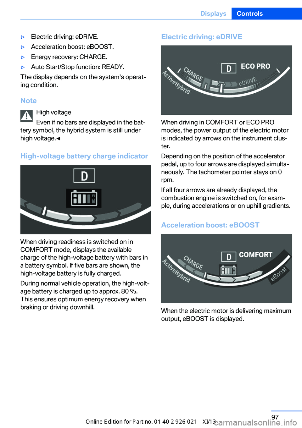
▷Electric driving: eDRIVE.▷Acceleration boost: eBOOST.▷Energy recovery: CHARGE.▷Auto Start/Stop function: READY.
The display depends on the system's operat‐
ing condition.
Note High voltage
Even if no bars are displayed in the bat‐
tery symbol, the hybrid system is still under high voltage.◀
High-voltage battery charge indicator
When driving readiness is switched on in
COMFORT mode, displays the available
charge of the high-voltage battery with bars in
a battery symbol. If five bars are shown, the
high-voltage battery is fully charged.
During normal vehicle operation, the high-volt‐
age battery is charged up to approx. 80 %.
This ensures optimum energy recovery when
braking or driving downhill.
Electric driving: eDRIVE
When driving in COMFORT or ECO PRO
modes, the power output of the electric motor
is indicated by arrows on the instrument clus‐
ter.
Depending on the position of the accelerator
pedal, up to four arrows are displayed simulta‐
neously. The tachometer pointer stays on 0
rpm.
If all four arrows are already displayed, the
combustion engine is switched on, for exam‐
ple, during accelerations or on uphill gradients.
Acceleration boost: eBOOST
When the electric motor is delivering maximum
output, eBOOST is displayed.
Seite 97DisplaysControls97
Online Edition for Part no. 01 40 2 909 774 - VI/13
Page 102 of 253
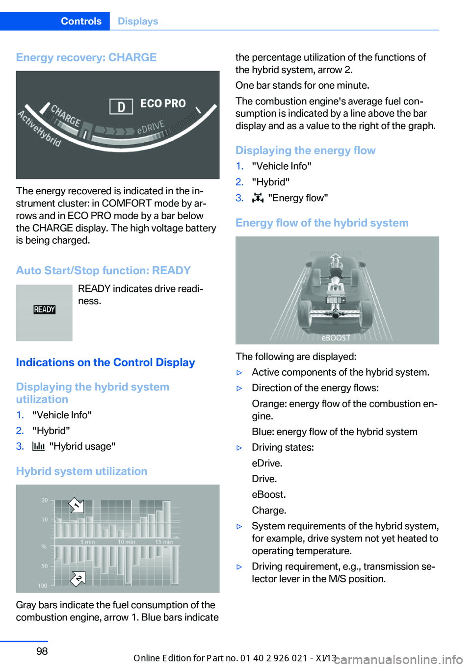
Energy recovery: CHARGE
The energy recovered is indicated in the in‐
strument cluster: in COMFORT mode by ar‐
rows and in ECO PRO mode by a bar below
the CHARGE display. The high voltage battery
is being charged.
Auto Start/Stop function: READY READY indicates drive readi‐
ness.
Indications on the Control Display Displaying the hybrid system
utilization
1."Vehicle Info"2."Hybrid"3. "Hybrid usage"
Hybrid system utilization
Gray bars indicate the fuel consumption of the
combustion engine, arrow 1. Blue bars indicate
the percentage utilization of the functions of
the hybrid system, arrow 2.
One bar stands for one minute.
The combustion engine's average fuel con‐
sumption is indicated by a line above the bar
display and as a value to the right of the graph.
Displaying the energy flow1."Vehicle Info"2."Hybrid"3. "Energy flow"
Energy flow of the hybrid system
The following are displayed:
▷Active components of the hybrid system.▷Direction of the energy flows:
Orange: energy flow of the combustion en‐
gine.
Blue: energy flow of the hybrid system▷Driving states:
eDrive.
Drive.
eBoost.
Charge.▷System requirements of the hybrid system,
for example, drive system not yet heated to
operating temperature.▷Driving requirement, e.g., transmission se‐
lector lever in the M/S position.Seite 98ControlsDisplays98
Online Edition for Part no. 01 40 2 909 774 - VI/13