ECU BMW ACTIVE HYBRID 7 2013 F04 Owner's Manual
[x] Cancel search | Manufacturer: BMW, Model Year: 2013, Model line: ACTIVE HYBRID 7, Model: BMW ACTIVE HYBRID 7 2013 F04Pages: 253, PDF Size: 5.01 MB
Page 30 of 253
Executing functions using short
commands
Functions on the main menu can be performed
directly by means of short commands, nearly
irrespective of which menu item is currently
selected, e.g., ›Vehicle status‹.
List of short commands of the voice activation
system, see Navigation, Entertainment, Com‐
munication Owner's Manual.
Help dialog for the voice activation
system
Calling up help dialog: ›Help‹
Additional commands for the help dialog:▷›Help with examples‹: information about the
current operating options and the most im‐
portant commands for them are an‐
nounced.▷›Help with voice activation‹: information
about the principle of operation for the
voice activation system is announced.
Example: playing back a CD
Via the main menu The commands of the menu items are spoken
just as they are selected via the controller.
1.Switch on the Entertainment sound output
if necessary.2. Press the button on the steering
wheel.3.›Multimedia‹
The medium last played is played back.4.›C D‹5.›C D drive‹6.›Track ...‹, e.g., CD track 4.Via short command
Playback of the CD can also be started via a
short command.1.Switch on the Entertainment sound output
if necessary.2. Press the button on the steering
wheel.3.›C D drive track ...‹, e.g., CD track 4.
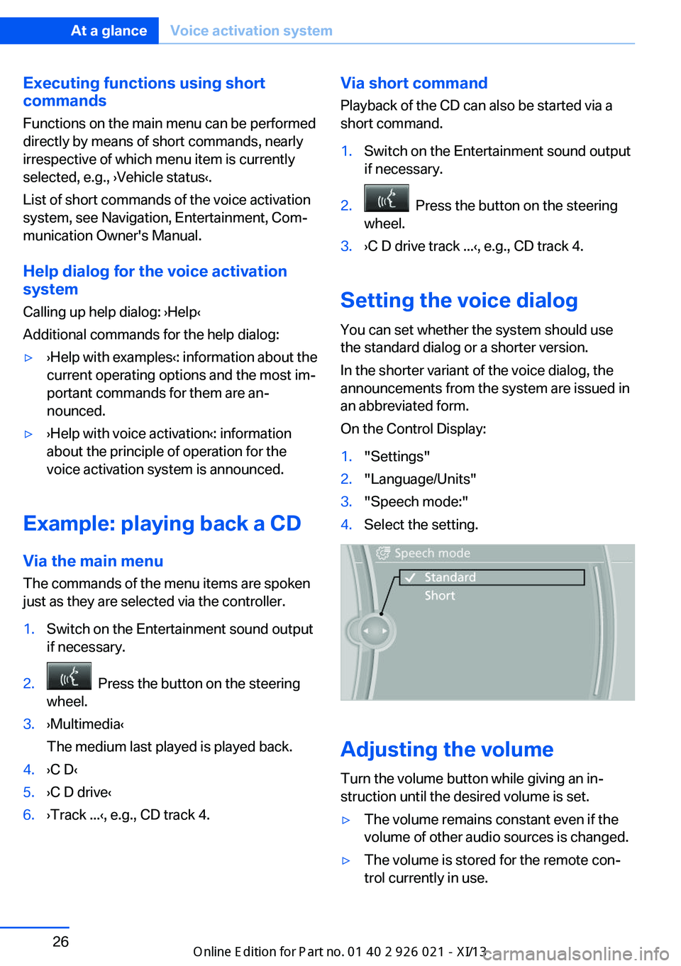
Setting the voice dialog
You can set whether the system should use
the standard dialog or a shorter version.
In the shorter variant of the voice dialog, the
announcements from the system are issued in
an abbreviated form.
On the Control Display:
1."Settings"2."Language/Units"3."Speech mode:"4.Select the setting.
Adjusting the volume
Turn the volume button while giving an in‐
struction until the desired volume is set.
▷The volume remains constant even if the
volume of other audio sources is changed.▷The volume is stored for the remote con‐
trol currently in use.Seite 26At a glanceVoice activation system26
Online Edition for Part no. 01 40 2 909 774 - VI/13
Page 33 of 253
Context help - Owner's Manual to the
temporarily selected function
The relevant information can be opened di‐
rectly.
Opening via the iDrive
To move directly from the application on the
Control Display to the options menu:1. Press the button or move the control‐
ler to the right repeatedly until the
"Options" menu is displayed.2."Display Owner's Manual"
Opening when a Check Control
message is displayed
Directly from the Check Control message on
the Control Display:
"Display Owner's Manual"
Changing between a function and the
Owner's Manual
To change from a function, e.g., radio, to the
Owner's Manual on the Control Display and to
switch between the two displays:
1. Press the button or move the control‐
ler to the right repeatedly until the
"Options" menu is displayed.2."Display Owner's Manual"3.Select the desired page in the Owner's
Manual.4. Press the button again to return to
the function displayed last.5. Press the button to return to the page
of the Owner's Manual displayed last.
To switch back and forth repeatedly between
the function displayed last and the page of the
Owner's Manual displayed last, repeat steps 4
and 5. This opens a new panel every time.
Programmable memory buttons
General information
The Owner's Manual can be stored on the pro‐
grammable memory buttons and called up di‐
rectly.
Storing1."Owner's Manual" Select via the iDrive.2. Press the desired button for more
than 2 seconds.
Executing
Press the button.
The Owner's Manual is displayed im‐
mediately.
Seite 29Integrated Owner's Manual in the vehicleAt a glance29
Online Edition for Part no. 01 40 2 909 774 - VI/13
Page 38 of 253
Opening and closingVehicle equipment
All standard, country-specific and optional
equipment that is offered in the model series is
described in this chapter. Therefore, equip‐
ment is also described that is not available in a
vehicle, e. g., because of the selected optional
equipment or country variant. This also applies
for safety-related functions and systems.
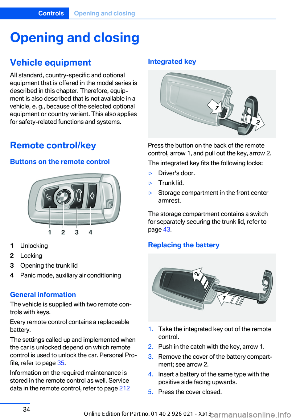
Remote control/key Buttons on the remote control1Unlocking2Locking3Opening the trunk lid4Panic mode, auxiliary air conditioning
General information
The vehicle is supplied with two remote con‐
trols with keys.
Every remote control contains a replaceable
battery.
The settings called up and implemented when
the car is unlocked depend on which remote
control is used to unlock the car. Personal Pro‐
file, refer to page 35.
Information on the required maintenance is
stored in the remote control as well. Service
data in the remote control, refer to page 212
Integrated key
Press the button on the back of the remote
control, arrow 1, and pull out the key, arrow 2.
The integrated key fits the following locks:
▷Driver's door.▷Trunk lid.▷Storage compartment in the front center
armrest.
The storage compartment contains a switch
for separately securing the trunk lid, refer to
page 43.
Replacing the battery
1.Take the integrated key out of the remote
control.2.Push in the catch with the key, arrow 1.3.Remove the cover of the battery compart‐
ment; see arrow 2.4.Insert a battery of the same type with the
positive side facing upwards.5.Press the cover closed.Seite 34ControlsOpening and closing34
Online Edition for Part no. 01 40 2 909 774 - VI/13
Page 40 of 253
Called up profile is assigned to the remote
control being used at the time.
Renaming profiles1."Settings"2."Profiles"
The current profile is selected.3.Open "Options".4."Rename current profile"
Resetting profiles The settings of the active profile are reset to
their default values.
1."Settings"2."Profiles"
The current profile is selected.3.Open "Options".4."Reset current profile"
Importing profiles
Existing settings and contacts are overwritten
with the imported profile.
1."Settings"2."Profiles"3."Import profile"4.BMW Online: "BMW Online"
USB interface, refer to page 171: "USB
device"
Exporting profiles
Most settings of the active profile and the
saved contacts can be exported.
This can be helpful for securing and retrieving
personal settings, before delivering the vehicle
to a workshop for example.
1."Settings"2."Profiles"3."Export profile"4.BMW Online: "BMW Online"USB interface, refer to page 171: "USB
device"
Using the guest profile
The guest profile can be used to make individ‐
ual settings without affecting the three Per‐
sonal Profiles.
This can be useful for drivers who are using
the vehicle temporarily and do not have their
own profile.
1."Settings"2."Profiles"
The current profile is selected.3.Open "Guest".4.Create the settings.
Note: the guest profile cannot be renamed.
Display profile list during start
The profile list can be displayed during each
start for selecting the desired profile.
1."Settings"2."Profiles"3.Open "Options".4."Display user list at startup"
Personal Profile settings
The following functions and settings can be
stored in a profile.
▷Collision warning: warning time.▷Exterior mirror position.▷CD/Multimedia: audio source listened to
last.▷Unlocking/locking of the vehicle: settings.▷Driving Dynamics Control: sport program.▷Driver's seat position: automatic retrieval
after unlocking.▷Programmable memory buttons: assign‐
ment.▷Head-up Display: selection, brightness,
position and rotation of the display.Seite 36ControlsOpening and closing36
Online Edition for Part no. 01 40 2 909 774 - VI/13
Page 44 of 253
Opening and closing: from
the inside
Locking and unlocking
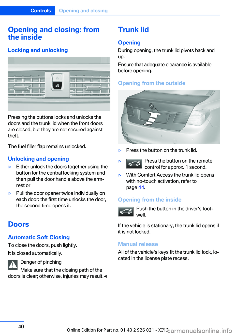
Pressing the buttons locks and unlocks the
doors and the trunk lid when the front doors
are closed, but they are not secured against
theft.
The fuel filler flap remains unlocked.
Unlocking and opening
▷Either unlock the doors together using the
button for the central locking system and
then pull the door handle above the arm‐
rest or▷Pull the door opener twice individually on
each door: the first time unlocks the door,
the second time opens it.
Doors
Automatic Soft Closing
To close the doors, push lightly.
It is closed automatically.
Danger of pinching
Make sure that the closing path of the
doors is clear; otherwise, injuries may result.◀
Trunk lid
Opening
During opening, the trunk lid pivots back and
up.
Ensure that adequate clearance is available
before opening.
Opening from the outside▷Press the button on the trunk lid.▷Press the button on the remote
control for approx. 1 second.▷With Comfort Access the trunk lid opens
with no-touch activation, refer to
page 44.
Opening from the inside
Push the button in the driver's foot‐
well.
If the vehicle is stationary, the trunk lid opens if
it is not locked.
Manual release All of the vehicle's keys fit the trunk lid lock, lo‐
cated in the license plate recess.
Seite 40ControlsOpening and closing40
Online Edition for Part no. 01 40 2 909 774 - VI/13
Page 47 of 253
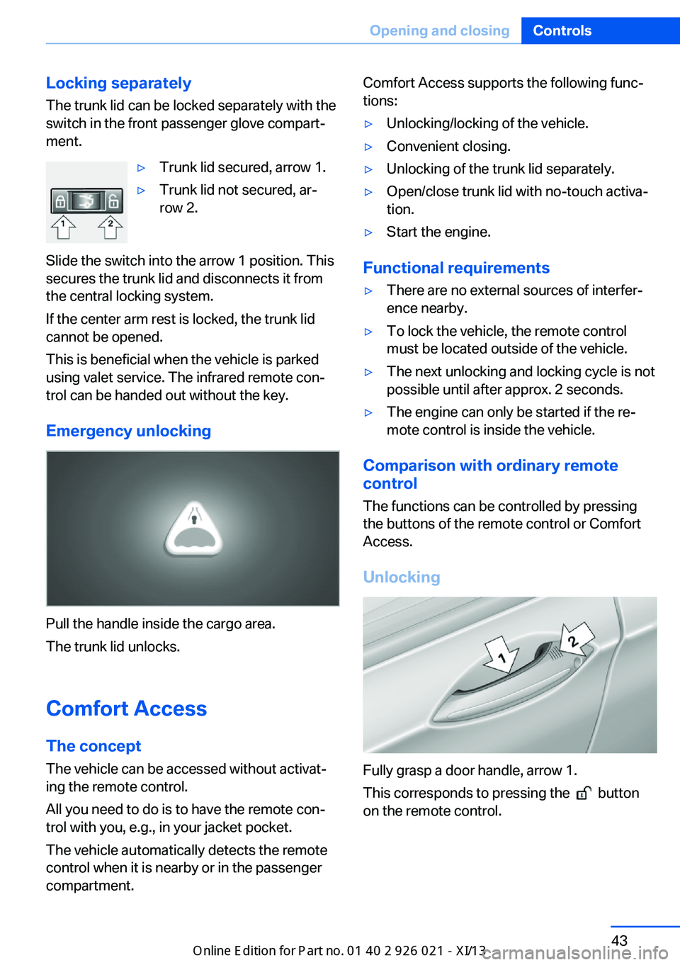
Locking separatelyThe trunk lid can be locked separately with theswitch in the front passenger glove compart‐
ment.▷Trunk lid secured, arrow 1.▷Trunk lid not secured, ar‐
row 2.
Slide the switch into the arrow 1 position. This
secures the trunk lid and disconnects it from
the central locking system.
If the center arm rest is locked, the trunk lid
cannot be opened.
This is beneficial when the vehicle is parked
using valet service. The infrared remote con‐
trol can be handed out without the key.
Emergency unlocking
Pull the handle inside the cargo area.
The trunk lid unlocks.
Comfort Access
The concept The vehicle can be accessed without activat‐
ing the remote control.
All you need to do is to have the remote con‐ trol with you, e.g., in your jacket pocket.
The vehicle automatically detects the remote
control when it is nearby or in the passenger
compartment.
Comfort Access supports the following func‐
tions:▷Unlocking/locking of the vehicle.▷Convenient closing.▷Unlocking of the trunk lid separately.▷Open/close trunk lid with no-touch activa‐
tion.▷Start the engine.
Functional requirements
▷There are no external sources of interfer‐
ence nearby.▷To lock the vehicle, the remote control
must be located outside of the vehicle.▷The next unlocking and locking cycle is not
possible until after approx. 2 seconds.▷The engine can only be started if the re‐
mote control is inside the vehicle.
Comparison with ordinary remote
control
The functions can be controlled by pressing the buttons of the remote control or Comfort
Access.
Unlocking
Fully grasp a door handle, arrow 1.
This corresponds to pressing the
button
on the remote control.
Seite 43Opening and closingControls43
Online Edition for Part no. 01 40 2 909 774 - VI/13
Page 53 of 253
▷Opening and closing of the rear windows
using the switches in the rear.▷Operation of the roller sunblinds using the
switches in the rear.▷Adjustment of the power rear seats.▷Adjustment of the power head restraints in
the rear.
Switching on and off
Press the button.
The LED lights up if the safety func‐
tion is switched on.
Safety switch for rear operation
Press the safety switch when transport‐
ing children in the rear; otherwise, injury may
result if the windows are closed without super‐
vision.◀
Roller sunblinds
General information
The safety switch in the driver's door can be
used to prevent children, for example, from op‐
erating the roller blinds using the switches in
the rear.
Press the safety switch in the driver's door.
The LED lights up if the safety function is
switched on.
If you are no longer able to move the roller
blinds after having activated them consecu‐
tively a number of times, the system is blocked
for a limited time to prevent overheating. Let
the system cool.
The roller sunblinds cannot be moved at low
interior temperatures.
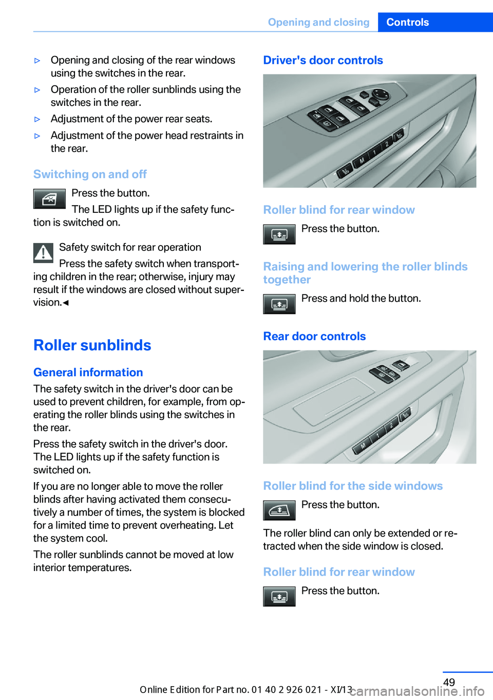
Driver's door controls
Roller blind for rear window
Press the button.
Raising and lowering the roller blinds together
Press and hold the button.
Rear door controls
Roller blind for the side windows Press the button.
The roller blind can only be extended or re‐
tracted when the side window is closed.
Roller blind for rear window Press the button.
Seite 49Opening and closingControls49
Online Edition for Part no. 01 40 2 909 774 - VI/13
Page 70 of 253
Transporting children safelyVehicle equipmentAll standard, country-specific and optional
equipment that is offered in the model series is
described in this chapter. Therefore, equip‐
ment is also described that is not available in a
vehicle, e. g., because of the selected optional
equipment or country variant. This also applies
for safety-related functions and systems.
The right place for children Note Children in the vehicle
Do not leave children unattended in the
vehicle; otherwise, they could endanger them‐
selves and other persons, e.g., by opening the
doors.◀
Children should always be in the rear
Accident research shows that the safest place
for children is in the back seat.
Transporting children in the rear
Only transport children younger than
13 years of age or shorter than 5 ft/150 cm in
the rear in child restraint fixing systems pro‐
vided in accordance with the age, weight and
size of the child; otherwise, there is an in‐
creased risk of injury in an accident.
Children 13 years of age or older must wear a
safety belt as soon as a suitable child restraint
fixing system can no longer be used, due to
their age, weight and size.◀
Children on the front passenger seat
Should it ever be necessary to use a child re‐
straint fixing system in the front passenger
seat, make sure that the front, knee and side
airbags on the front passenger side are deacti‐vated. Automatic deactivation of front passen‐
ger side airbags, refer to page 107.
Note Deactivated front passenger airbags
If a child restraint fixing system is used in
the front passenger seat, the front passenger
airbags must be deactivated; otherwise, there
is an increased risk of injury to the child when
the airbags are triggered, even with a child re‐
straint fixing system.◀
Installing child restraint
fixing systems
Before mounting
If the rear seat backrests are adjustable or can
be folded down:
Lock the rear seat backrests in position
Before mounting child restraint fixing
systems, place the seat backrest as far as pos‐
sible at an angle at which the child seat is rest‐
ing firmly against the backrest and all back‐
rests can be locked securely in place.
Otherwise, the child seat will not be as stable
as it should be, and there is increased danger
of injury due to unexpected movement of the
seat backrest.◀
Hints Manufacturer's information for child re‐
straint fixing systems
To select, mount and use child restraint fixing
systems, observe the information provided by
the system manufacturer; otherwise, the pro‐
tective effect can be impaired.◀Seite 66ControlsTransporting children safely66
Online Edition for Part no. 01 40 2 909 774 - VI/13
Page 71 of 253
Lock the rear seat backrests in position
Before installing a child restraint system,
make sure that the rear seat backrests are
locked; otherwise, the protective effect is not
guaranteed and there is an increased risk of in‐
jury for the child in the event of an accident.◀
On the front passenger seat
Deactivating airbags
After installing a child restraint fixing system in
the front passenger seat, make sure that the
front, knee and side airbags on the front pas‐
senger side are deactivated.
Deactivate the front passenger airbags auto‐
matically, refer to page 107.
Deactivating the front passenger airbags
If a child restraint fixing system is used in
the front passenger seat, the front passenger
airbags must be deactivated; otherwise, there
is an increased risk of injury to the child when
the airbags are triggered, even with a child re‐
straint fixing system.◀
Seat position and height
Before installing a child restraint fixing system,
move the front passenger seat as far back as
possible and bring it up to medium height to
obtain the best possible position for the belt
and to offer optimal protection in the event of
an accident.
Do not change the seat position and height af‐
ter this.
Backrest width Adjustable backrest width: before installing a
child restraint fixing system in the front pas‐
senger seat, open the backrest width com‐
pletely. Do not change the backrest width
again and do not call up a memory position.Backrest width for the child seat
Before installing a child restraint fixing
system in the front passenger seat, the back‐
rest width must be opened completely. Do not
change the adjustment after this; otherwise,
the stability of the child seat will be reduced.◀
Child seat security
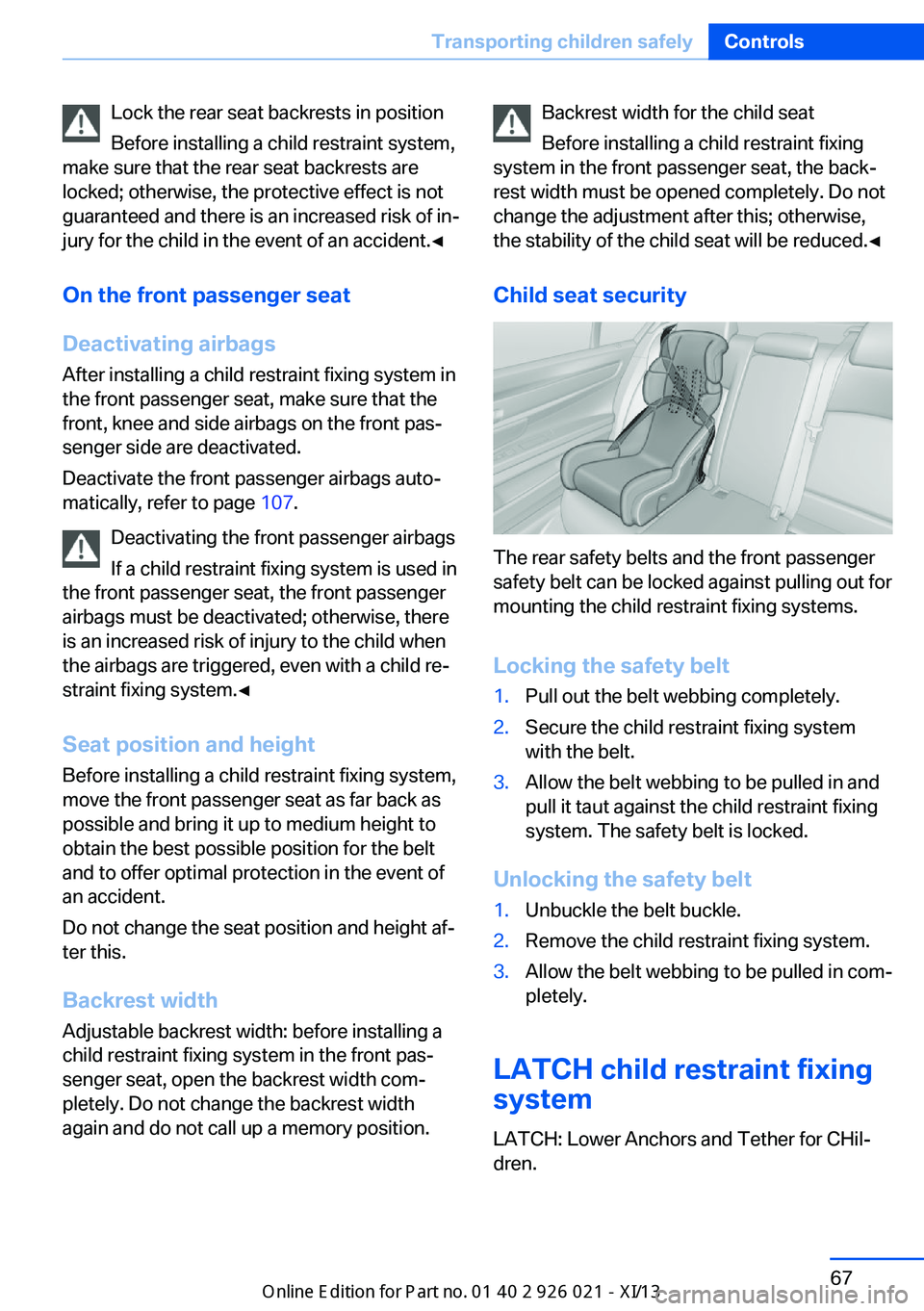
The rear safety belts and the front passenger
safety belt can be locked against pulling out for
mounting the child restraint fixing systems.
Locking the safety belt
1.Pull out the belt webbing completely.2.Secure the child restraint fixing system
with the belt.3.Allow the belt webbing to be pulled in and
pull it taut against the child restraint fixing
system. The safety belt is locked.
Unlocking the safety belt
1.Unbuckle the belt buckle.2.Remove the child restraint fixing system.3.Allow the belt webbing to be pulled in com‐
pletely.
LATCH child restraint fixing
system
LATCH: Lower Anchors and Tether for CHil‐dren.
Seite 67Transporting children safelyControls67
Online Edition for Part no. 01 40 2 909 774 - VI/13
Page 72 of 253
NoteManufacturer's information for LATCHchild restraint fixing systems
To mount and use the LATCH child restraint
fixing systems, observe the operating and
safety information from the system manufac‐
turer; otherwise, the level of protection may be
reduced.◀
Mounts for the lower LATCH anchors
The lower anchors may be used to attach the
CRS to the vehicle seat up to a combined child
and CRS weight of 65 lb/30 kg when the child
is restr- ained by the internal harnesses.
Correctly engage the lower LATCH an‐
chors
Make sure that the lower LATCH anchors have
properly engaged and that the child restraint
fixing system is resting snugly against the
backrest; otherwise, the degree of protection
offered may be reduced.◀
Before mounting the LATCH child restraint fix‐
ing system, pull the belt away from the child
restraint fixing system.
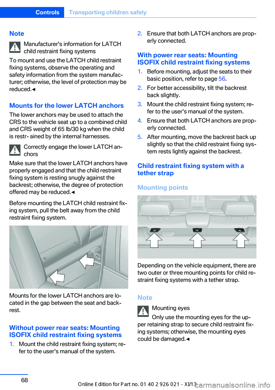
Mounts for the lower LATCH anchors are lo‐
cated in the gap between the seat and back‐
rest.
Without power rear seats: Mounting ISOFIX child restraint fixing systems
1.Mount the child restraint fixing system; re‐
fer to the user's manual of the system.2.Ensure that both LATCH anchors are prop‐
erly connected.
With power rear seats: Mounting
ISOFIX child restraint fixing systems
1.Before mounting, adjust the seats to their
basic position, refer to page 56.2.For better accessibility, tilt the backrest
back slightly.3.Mount the child restraint fixing system; re‐
fer to the user's manual of the system.4.Ensure that both LATCH anchors are prop‐
erly connected.5.After mounting, move the backrest back up
slightly so that the child restraint fixing sys‐
tem rests lightly against the backrest.
Child restraint fixing system with a
tether strap
Mounting points
Depending on the vehicle equipment, there are
two outer or three mounting points for child re‐
straint fixing systems with a tether strap.
Note Mounting eyes
Only use the mounting eyes for the up‐
per retaining strap to secure child restraint fix‐
ing systems; otherwise, the mounting eyes
could be damaged.◀
Seite 68ControlsTransporting children safely68
Online Edition for Part no. 01 40 2 909 774 - VI/13