check engine BMW ACTIVE HYBRID 7 2014 F01H User Guide
[x] Cancel search | Manufacturer: BMW, Model Year: 2014, Model line: ACTIVE HYBRID 7, Model: BMW ACTIVE HYBRID 7 2014 F01HPages: 257, PDF Size: 5.44 MB
Page 122 of 257
All wheels are yellowA flat tire or major drop in inflation pressure in
several tires.
Wheels, gray The system cannot detect a flat tire. Reasons
for this may be:▷The system is being reset.▷Malfunction.
Status information
The status control display additionally shows
the current tire inflation pressures and possibly
tire temperatures. It shows the actual values
read; they may vary depending on driving style or weather conditions.
Carry out reset
Reset the system after each adjustment of the
tire inflation pressure and after every tire or
wheel change.
On the Control Display and on the vehicle:
1."Vehicle info"2."Vehicle status"3. "Perform reset"4.Start the engine - do not drive off.5.Reset tire inflation pressure:"Perform
reset".6.Drive away.
The tires are shown in gray and the status is
displayed.
After driving faster than 19 mph/30 km/h for a
short period, the set tire inflation pressures are
accepted as reference values. The reset is
completed automatically while driving.
After a successfully completed Reset, the
wheels on the Control Display are shown in
green and "Tire Pressure Monitor (TPM)
active" is displayed.
You may interrupt this trip at any time. When
you continue the reset resumes automatically.
Low tire pressure message
The yellow warning lamp lights up. A
Check Control message is displayed.▷There is a flat tire or a major loss in
tire inflation pressure.▷No reset was performed for the system.
The system therefore issues a warning
based on the tire inflation pressures before
the last reset.1.Reduce your speed and stop cautiously.
Avoid sudden braking and steering maneu‐
vers.2.Check whether the vehicle is fitted with
regular tires or run-flat tires.
Run-flat tires, refer to page 210, are la‐
beled with a circular symbol containing the
letters RSC marked on the tire's sidewall.
Do not continue driving without run-flat
tires
Do not continue driving if the vehicle is not
equipped with run-flat tires; continued driving
may result in serious accidents.◀
A low tire inflation pressure might turn on DSC
Dynamic Stability Control.
Actions in the event of a flat tireNormal tires
1.Identify the damaged tire.
Do this by checking the air pressure in all
four tires.
If the tire inflation pressure in all four tires
is shown to be correct, it is possible that
the Tire Pressure Monitor did not perform
a reset. Then perform the reset.
If an identification is not possible, please
contact the service center.2.Fixing a flat tire, where applicable with the
Mobility System.Seite 118ControlsSafety118
Online Edition for Part no. 01 40 2 956 056 - X/14
Page 124 of 257
MalfunctionThe yellow warning lamp flashes andthen lights up continuously. A Check
Control message is displayed. No flat
tire or loss of tire inflation pressure can be de‐
tected.
Display in the following situations:▷A wheel without TPM electronics is fitted:
have the service center check it if needed.▷Malfunction: have the system checked by
your service center.▷TPM was unable to complete the reset.
Reset the system again.▷Interference through systems or devices
with the same radio frequency: after leav‐
ing the area of the interference, the system
automatically becomes active again.
Declaration according to NHTSA/
FMVSS 138 Tire Pressure Monitoring
System
Each tire, including the spare (if provided)
should be checked monthly when cold and in‐
flated to the inflation pressure recommended
by the vehicle manufacturer on the vehicle
placard or tire inflation pressure label. (If your
vehicle has tires of a different size than the size
indicated on the vehicle placard or tire inflation
pressure label, you should determine the
proper tire inflation pressure for those tires.)
As an added safety feature, your vehicle has
been equipped with a tire pressure monitoring
system (TPMS) that illuminates a low tire pres‐
sure telltale when one or more of your tires is
significantly under-inflated. Accordingly, when
the low tire pressure telltale illuminates, you
should stop and check your tires as soon as
possible, and inflate them to the proper pres‐
sure. Driving on a significantly under-inflated
tire causes the tire to overheat and can lead to
tire failure. Under-inflation also reduces fuel ef‐
ficiency and tire tread life, and may affect the
vehicle's handling and stopping ability. Please
note that the TPMS is not a substitute for
proper tire maintenance, and it is the driver's
responsibility to maintain correct tire pressure,
even if under-inflation has not reached the
level to trigger illumination of the TPMS low
tire pressure telltale. Your vehicle has also
been equipped with a TPMS malfunction indi‐
cator to indicate when the system is not oper‐
ating properly. The TPMS malfunction indica‐
tor is combined with the low tire pressure
telltale. When the system detects a malfunc‐
tion, the telltale will flash for approximately one
minute and then remain continuously illumi‐
nated. This sequence will continue upon sub‐
sequent vehicle start-ups as long as the mal‐
function exists. When the malfunction indicator
is illuminated, the system may not be able to
detect or signal low tire pressure as intended.
TPMS malfunctions may occur for a variety of
reasons, including the installation of replace‐
ment or alternate tires or wheels on the vehicle
that prevent the TPMS from functioning prop‐
erly. Always check the TPMS malfunction tell‐
tale after replacing one or more tires or wheels
on your vehicle to ensure that the replacement
or alternate tires and wheels allow the TPMS
to continue to function properly.
Intelligent Safety The conceptIntelligent Safety enables central operation of
the driver assistance system.
Depending on how the vehicle is equipped, In‐
telligent Safety consists of one or more sys‐
tems that can help prevent a imminent colli‐
sion. These systems are active automatically
every time the engine is started using the
Start/Stop button:▷Front-end collision warning, refer to
page 121.▷Pedestrian warning, refer to page 127.Seite 120ControlsSafety120
Online Edition for Part no. 01 40 2 956 056 - X/14
Page 157 of 257
Brief status displaySelected desired speed.
If --- appears briefly on the display for Check
Control messages, it is possible that the sys‐
tem requirements are currently not ready for
operations.
Displays in the Head-up Display Some system information can also be dis‐played in the Head-up Display.
PDC Park Distance Control
The concept PDC is a support when parking. When you
slowly approach an object in the rear - or also
in the front of the vehicle if the feature is availa‐
ble - then the object is reported through:▷Signal tones.▷Visual display.
General information
Ultrasound sensors in the bumpers measure
the distances from objects.
The maneuvering range, depending on the ob‐
stacle and environmental conditions, is approx.
6 ft/2 m.
An acoustic warning is first given:
▷By the front sensors and the two rear cor‐
ner sensors at approx. 24 in/60 cm.▷By the rear middle sensors at approx.
5 ft/1.50 m.
To ensure full functionality:
▷Do not cover sensors, e.g., with stickers,
bicycle racks and the like.▷Keep the sensors clean and free of ice.▷When using high-pressure washers, do not
spray the sensors for long periods and
maintain a distance of at least 12 in/30 cm.Hints
Personal responsibility
Even an active system does not relieve
the driver from personal responsibility while
driving.
Technically the system has its limits, it cannot
independently react to all traffic situations.
Monitor your driving, be on the alert, observe
the vehicle surroundings and other traffic and
react when needed - risk of accident.◀
Avoid driving fast with PDC
Avoid approaching an object too fast.
Avoid driving off fast while PDC is not yet ac‐
tive.
For technical reasons, the system may other‐
wise be too late in issuing a warning.◀
At a glance
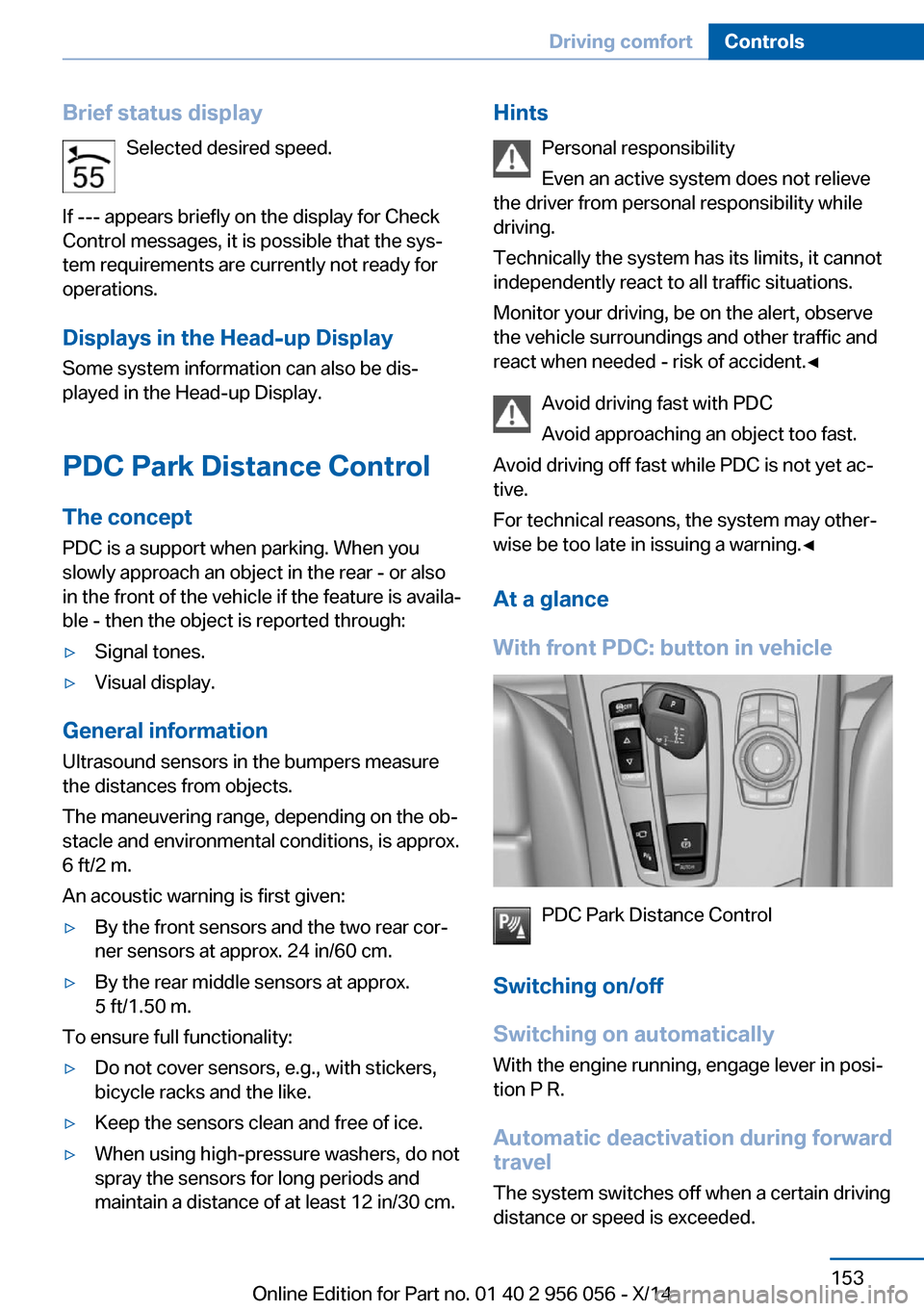
With front PDC: button in vehicle
PDC Park Distance Control
Switching on/off
Switching on automatically With the engine running, engage lever in posi‐
tion P R.
Automatic deactivation during forward
travel
The system switches off when a certain driving
distance or speed is exceeded.
Seite 153Driving comfortControls153
Online Edition for Part no. 01 40 2 956 056 - X/14
Page 165 of 257
track line is continuously adjusted for the
steering wheel movement.
"Parking aid lines"
Turning circle and pathway lines are displayed.
System limits
Top View cannot be used in the following sit‐
uations:
▷With a door open.▷With the trunk lid open.▷With an exterior mirror folded in.▷In poor light.
A Check Control message is displayed in some
of these situations.
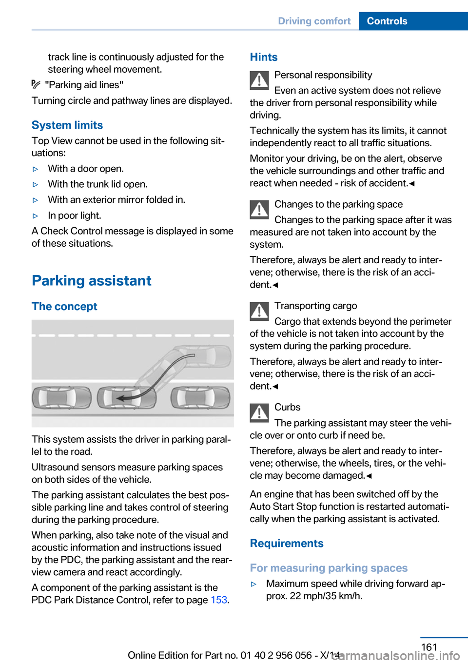
Parking assistant The concept
This system assists the driver in parking paral‐
lel to the road.
Ultrasound sensors measure parking spaces
on both sides of the vehicle.
The parking assistant calculates the best pos‐
sible parking line and takes control of steering
during the parking procedure.
When parking, also take note of the visual and
acoustic information and instructions issued
by the PDC, the parking assistant and the rear‐
view camera and react accordingly.
A component of the parking assistant is the
PDC Park Distance Control, refer to page 153.
Hints
Personal responsibility
Even an active system does not relieve
the driver from personal responsibility while
driving.
Technically the system has its limits, it cannot
independently react to all traffic situations.
Monitor your driving, be on the alert, observe
the vehicle surroundings and other traffic and
react when needed - risk of accident.◀
Changes to the parking space
Changes to the parking space after it was
measured are not taken into account by the system.
Therefore, always be alert and ready to inter‐
vene; otherwise, there is the risk of an acci‐
dent.◀
Transporting cargo
Cargo that extends beyond the perimeter
of the vehicle is not taken into account by the
system during the parking procedure.
Therefore, always be alert and ready to inter‐
vene; otherwise, there is the risk of an acci‐
dent.◀
Curbs
The parking assistant may steer the vehi‐
cle over or onto curb if need be.
Therefore, always be alert and ready to inter‐
vene; otherwise, the wheels, tires, or the vehi‐
cle may become damaged.◀
An engine that has been switched off by the
Auto Start Stop function is restarted automati‐
cally when the parking assistant is activated.
Requirements
For measuring parking spaces▷Maximum speed while driving forward ap‐
prox. 22 mph/35 km/h.Seite 161Driving comfortControls161
Online Edition for Part no. 01 40 2 956 056 - X/14
Page 191 of 257
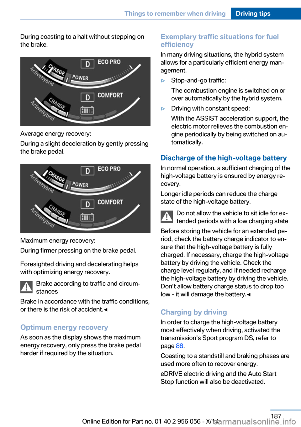
During coasting to a halt without stepping on
the brake.
Average energy recovery:
During a slight deceleration by gently pressing
the brake pedal.
Maximum energy recovery:
During firmer pressing on the brake pedal.
Foresighted driving and decelerating helps
with optimizing energy recovery.
Brake according to traffic and circum‐
stances
Brake in accordance with the traffic conditions,
or there is the risk of accident.◀
Optimum energy recovery As soon as the display shows the maximum
energy recovery, only press the brake pedal
harder if required by the situation.
Exemplary traffic situations for fuel efficiency
In many driving situations, the hybrid system
allows for a particularly efficient energy man‐
agement.▷Stop-and-go traffic:
The combustion engine is switched on or
over automatically by the hybrid system.▷Driving with constant speed:
With the ASSIST acceleration support, the
electric motor relieves the combustion en‐
gine periodically by being switched on au‐
tomatically.
Discharge of the high-voltage battery
In normal operation, a sufficient charging of the
high-voltage battery is ensured by energy re‐
covery.
Longer idle periods can reduce the charge
state of the high-voltage battery.
Do not allow the vehicle to sit idle for ex‐
tended periods with a low charging state
Before storing the vehicle for an extended pe‐
riod, check the battery charge indicator to en‐
sure that the high-voltage battery is fully
charged. If necessary, charge the high-voltage
battery by driving the vehicle. Check the
charge level regularly, and if needed recharge
the high-voltage battery by driving the vehicle.
Don't allow battery charge status to drop too
low - it will damage the battery.◀
Charging by driving
In order to charge the high-voltage battery
most effectively when driving, activated the
transmission's Sport program DS, refer to
page 88.
Coasting to a standstill and braking phases are used more often to recover energy.
eDRIVE electric driving and the Auto Start
Stop function will also be deactivated.
Seite 187Things to remember when drivingDriving tips187
Online Edition for Part no. 01 40 2 956 056 - X/14
Page 192 of 257
Fast chargingIn exceptional cases it can be charged in place,
such as before extended idle phases in order
to prevent damage to the high-voltage battery.1.Start the engine.2.Engage transmission position P and set
parking brake.3.Press and hold down brake pedal.4.Use the accelerator pedal to maintain an
engine speed of approx. 2,000 rpm.
After a few minutes, the high-voltage battery is
fully charged again.
The battery charge indicator in the instrument
cluster, refer to page 91, is used to check the
status.
General driving notes
Closing the trunk lid Drive with the trunk lid closed
Only drive with the tailgate closed; other‐
wise, in the event of an accident or braking and
evasive maneuvers, passengers and other traf‐
fic may be injured, and the vehicle may be
damaged. In addition, exhaust fumes may en‐
ter the vehicle interior.◀
If driving with the tailgate open cannot be
avoided:
▷Close all windows and the glass sunroof.▷Greatly increase the air flow from the vents.▷Drive moderately.
Hot exhaust system
Hot exhaust system
High temperatures are generated in the
exhaust system.
Do not remove the heat shields installed and
never apply undercoating to them. Make sure
that flammable materials, e. g. hay, leaves,
grass, etc. do not come in contact with the hot
exhaust system while driving, while in idle po‐
sition mode, or when parked. Such contact
could lead to a fire, resulting in an increased
risk of serious personal injury as well as prop‐
erty damage.
Do not touch hot exhaust pipes; otherwise,
there is a danger of getting burned.◀
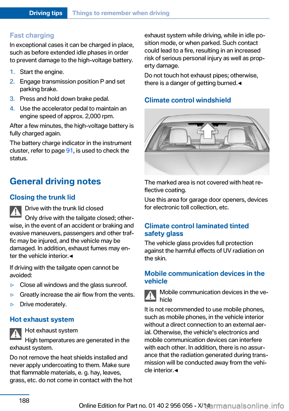
Climate control windshield
The marked area is not covered with heat re‐
flective coating.
Use this area for garage door openers, devices
for electronic toll collection, etc.
Climate control laminated tinted
safety glass
The vehicle glass provides full protection
against the harmful effects of UV radiation on
the skin.
Mobile communication devices in thevehicle
Mobile communication devices in the ve‐
hicle
It is not recommended to use mobile phones,
such as mobile phones, in the vehicle interior
without a direct connection to an external aer‐
ial. Otherwise, the vehicle's electronics and
mobile communication devices can interfere
with each other. In addition, there is no assur‐
ance that the radiation generated during trans‐
mission will be conducted away from the vehi‐
cle interior.◀
Seite 188Driving tipsThings to remember when driving188
Online Edition for Part no. 01 40 2 956 056 - X/14
Page 198 of 257
Saving fuelVehicle features and optionsThis chapter describes all standard, country-
specific and optional features offered with the
series. It also describes features that are not
necessarily available in your car, e. g., due to
the selected options or country versions. This
also applies to safety-related functions and
systems.
General information
Your vehicle contains advanced technology for
the reduction of fuel consumption and emis‐
sions.
Fuel consumption depends on a number of dif‐
ferent factors.
Carrying out certain measures, such as a mod‐
erate driving style and regular maintenance,
can influence fuel consumption and the envi‐
ronmental impact.
Remove unnecessary cargoAdditional weight increases fuel consumption.
Remove attached parts
following use
Remove auxiliary mirrors, roof or rear luggage
racks which are no longer required following
use.
Attached parts on the vehicle impair the aero‐
dynamics and increase the fuel consumption.Close the windows and glass
sunroof
Driving with the glass sunroof and windows
open results in increased air resistance and
thereby reduces the range.
Tires
General information Tires can affect fuel consumption in various
ways, e.g., tire size may influence fuel con‐
sumption.
Check the tire inflation pressure
regularly
Check and, if needed, correct the tire inflation
pressure at least twice a month and before
starting on a long trip.
Low tire inflation pressure increases rolling re‐
sistance and thus raises fuel consumption and
tire wear.
Drive away immediately
Do not wait for the engine to warm-up while
the vehicle remains stationary. Start driving
right away, but at moderate engine speeds.
This is the quickest way of warming the cold
engine up to operating temperature.
Look well ahead when
driving
Avoid unnecessary acceleration and braking.
By maintaining a suitable distance to the vehi‐
cle driving ahead of you.
Driving smoothly and proactively reduces fuel
consumption.Seite 194Driving tipsSaving fuel194
Online Edition for Part no. 01 40 2 956 056 - X/14
Page 218 of 257
Engine oilVehicle features and options
This chapter describes all standard, country-
specific and optional features offered with the
series. It also describes features that are not
necessarily available in your car, e. g., due to
the selected options or country versions. This
also applies to safety-related functions and
systems.
General information
The engine oil consumption is dependent on
the driving style and driving conditions.
The engine oil consumption can increase in
case of, for example:▷Sporty driving.▷Break-in the engine.▷Idling of the engine.▷Usage of non-approved engine oil grades.
Therefore, regularly check the engine oil level
after refueling.
The vehicle is equipped with electronic oil
measurement.
The electronic oil measurement has two meas‐
uring principles:
▷Status display▷Detailed measurement
Electronic oil measurement
Status display
The concept
The engine oil level is monitored electronically
while driving and shown on the Control Dis‐
play.
If the engine oil level reaches the minimum
level, a check control message is displayed.
Requirements
A current measured value is available after ap‐
prox. 30 minutes of driving. During a shorter
trip, the status of the last, sufficiently long trip
is displayed.
With frequent short-distance trips, regularly
perform a detailed measurement.
Displaying the engine oil level
On the Control Display:1."Vehicle info"2."Vehicle status"3. "Engine oil level"
Engine oil level display messages
Different messages appear on the display de‐
pending on the engine oil level. Pay attention
to these messages.
If the engine oil level is too low, within the next
125 miles/200 km Add engine oil, refer to
page 215.
Engine oil level too low
Add engine oil immediately; otherwise,
an insufficient amount of engine oil could re‐
sult in engine damage.◀
Take care not to add too much engine oil. Too much engine oil
Have the vehicle checked immediately;
otherwise, surplus engine oil can lead to en‐
gine damage.◀
Seite 214MobilityEngine oil214
Online Edition for Part no. 01 40 2 956 056 - X/14
Page 219 of 257
Detailed measurement
The concept In the detailed measurement the engine oil
level is checked and displayed via a scale.
During the measurement, the idle speed is in‐
creased somewhat.
General information
A detailed measurement is only possible with
certain engines.
Requirements▷Vehicle is on level road.▷Steptronic transmission: selector lever in
selector lever position N or P and accelera‐
tor pedal not depressed.▷Engine is running and is at operating tem‐
perature.
Performing a detailed measurement
In order to perform a detailed measurement of
the engine oil level:
1."Vehicle info"2."Vehicle status"3. "Measure engine oil level"4."Start measurement"
The engine oil level is checked and displayed
via a scale.
Time: approx. 1 minute.
Adding engine oil General information
Switch off the ignition and safely park the vehi‐
cle before engine oil is added.
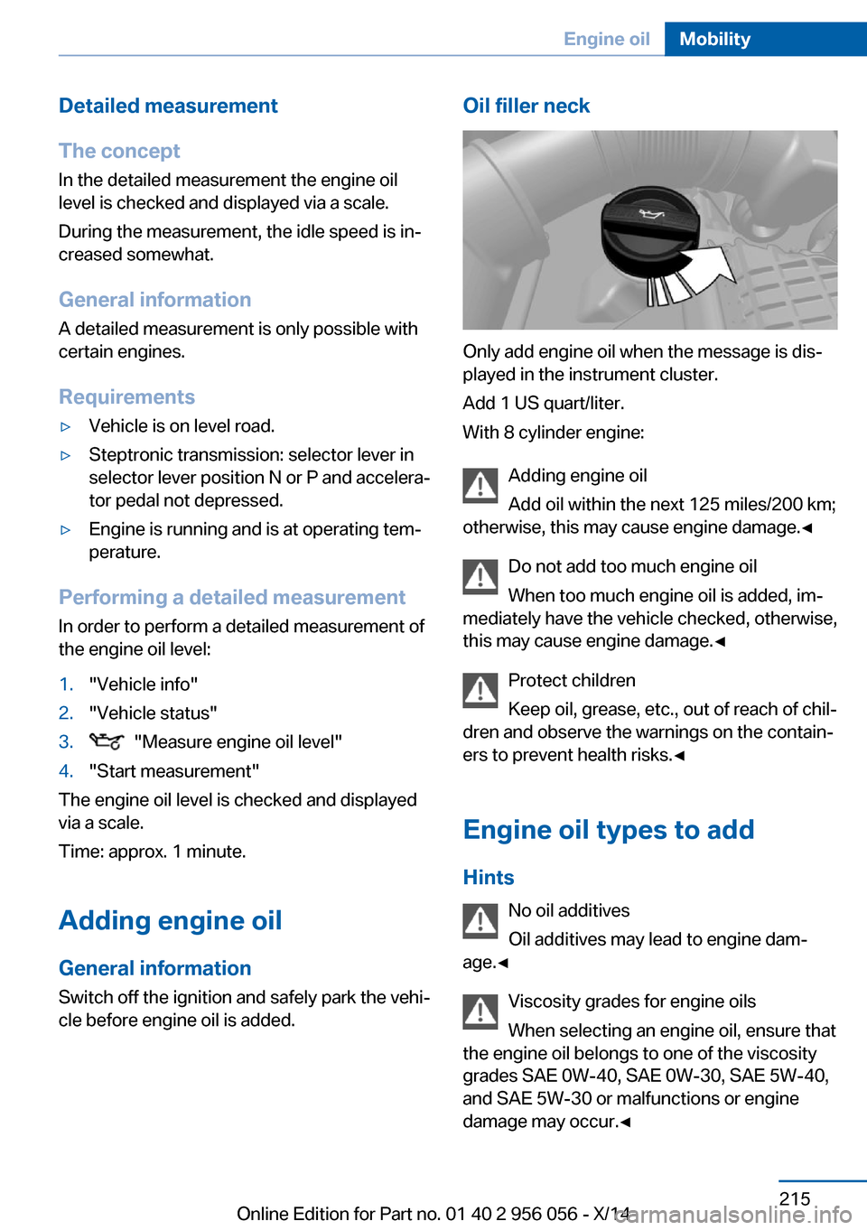
Oil filler neck
Only add engine oil when the message is dis‐
played in the instrument cluster.
Add 1 US quart/liter.
With 8 cylinder engine:
Adding engine oil
Add oil within the next 125 miles/200 km;
otherwise, this may cause engine damage.◀
Do not add too much engine oil
When too much engine oil is added, im‐
mediately have the vehicle checked, otherwise,
this may cause engine damage.◀
Protect children
Keep oil, grease, etc., out of reach of chil‐
dren and observe the warnings on the contain‐
ers to prevent health risks.◀
Engine oil types to add Hints No oil additives
Oil additives may lead to engine dam‐
age.◀
Viscosity grades for engine oils
When selecting an engine oil, ensure that
the engine oil belongs to one of the viscosity
grades SAE 0W-40, SAE 0W-30, SAE 5W-40,
and SAE 5W-30 or malfunctions or engine
damage may occur.◀
Seite 215Engine oilMobility215
Online Edition for Part no. 01 40 2 956 056 - X/14
Page 221 of 257
CoolantVehicle features and optionsThis chapter describes all standard, country-
specific and optional features offered with the
series. It also describes features that are not
necessarily available in your car, e. g., due to
the selected options or country versions. This
also applies to safety-related functions and
systems.
Hints Danger of burns from hot engine
Do not open the cooling system while
the engine is hot; otherwise, esliding coolant
may cause burns.◀
Suitable additives
Only use suitable additives; otherwise,
engine damage may occur. The additives are
harmful to your health.◀
Coolant consists of water and additives.
Not all commercially available additives are
suitable for the vehicle. Information about the
suitable additives are available from the service
center.
Coolant level
General information If there is no Min. and Max. mark in the filler
neck of the coolant reservoir, have the coolant
level checked if needed by your service center
and add coolant as needed.
Depending on the engine installation, the cool‐
ant reservoir is located on the right side or the
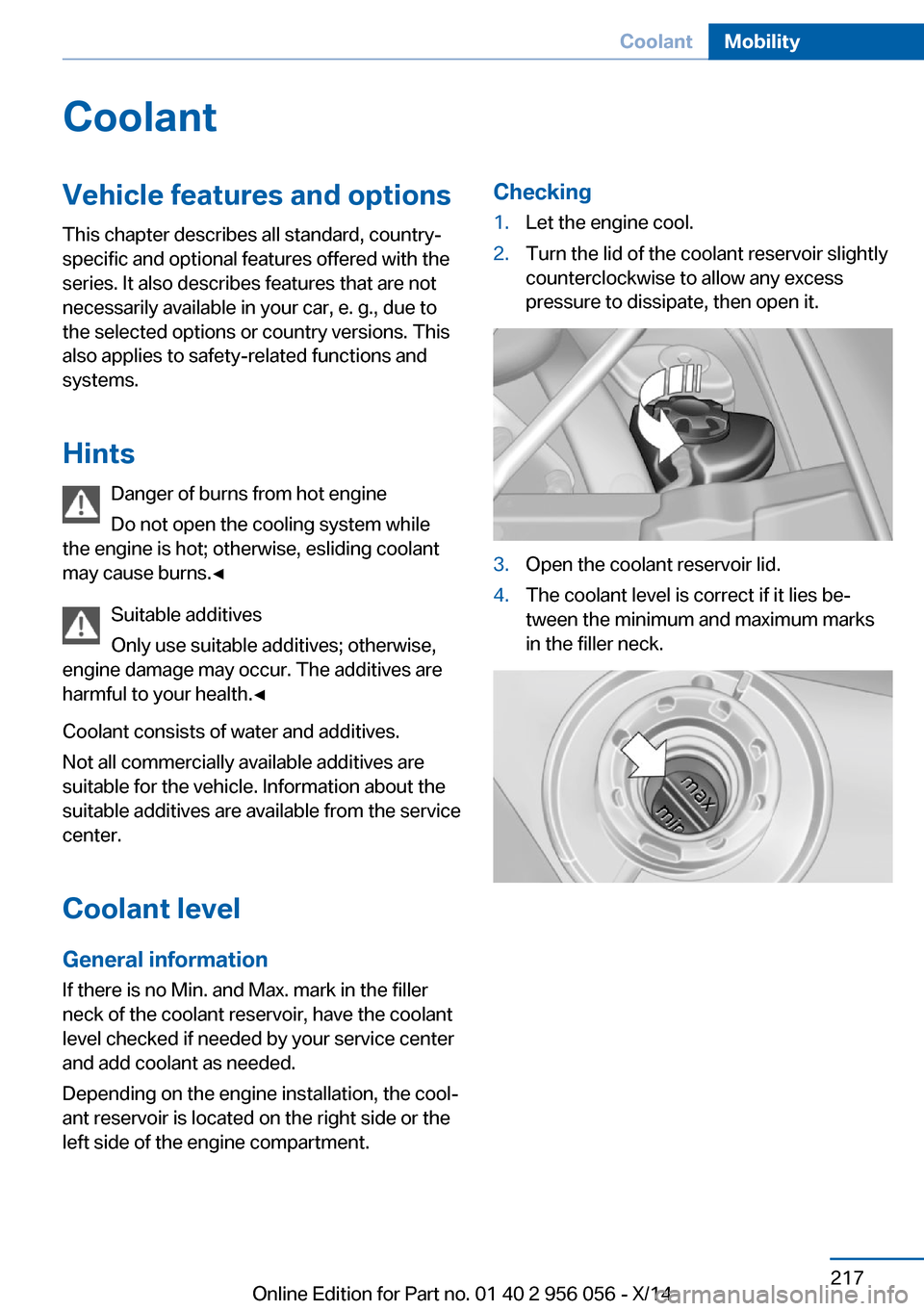
left side of the engine compartment.Checking1.Let the engine cool.2.Turn the lid of the coolant reservoir slightly
counterclockwise to allow any excess
pressure to dissipate, then open it.3.Open the coolant reservoir lid.4.The coolant level is correct if it lies be‐
tween the minimum and maximum marks
in the filler neck.Seite 217CoolantMobility217
Online Edition for Part no. 01 40 2 956 056 - X/14