sensor BMW ACTIVEHYBRID5 2013 User Guide
[x] Cancel search | Manufacturer: BMW, Model Year: 2013, Model line: ACTIVEHYBRID5, Model: BMW ACTIVEHYBRID5 2013Pages: 224, PDF Size: 4.96 MB
Page 124 of 224
Displays in the instrument cluster
Indicator lamp Depending on how the vehicle is equip‚Äź
ped, the indicator lamp in the instrument
cluster indicates whether the system is
switched on.
Desired speed‚Ė∑The marking lights up green:
the system is active.‚Ė∑The marking lights up or‚Äź
ange: the system has been
interrupted.‚Ė∑The marking does not light up: the system is
switched off.
Brief status display
Selected desired speed.
If --- appears briefly on the display for Check
Control messages, it is possible that the system
requirements for operation are currently not
met.
PDC Park Distance Control
The concept
PDC supports you when parking. Objects that
you are approaching slowly in front of or behind
your vehicle are indicated by:
‚Ė∑Signal tones.‚Ė∑Visual display.
General information
Measurements are made by ultrasound sensors
in the bumpers.
The range is approx. 6 ft/2 m.
An acoustic warning is first given:
‚Ė∑By the front sensors and the two rear corner
sensors at approx. 24 in/60 cm.‚Ė∑By the rear middle sensors at approx.
5 ft/1.50 m.
Notes
Check the traffic situation as well
PDC cannot serve as a substitute for the
driver's personal judgment of the traffic situa‚Äź
tion. Check the traffic situation around the vehi‚Äź
cle with your own eyes. Otherwise, an accident
could result from road users or objects located
outside of the PDC detection range.
Loud noises from outside and inside the vehicle
may prevent you from hearing the PDC's signal
tone.‚óÄ
Avoid driving quickly with PDC
Avoid approaching an object quickly.
Avoid driving away quickly while PDC is not yet
active.
For technical reasons, the system may other‚Äź
wise be too late in issuing a warning.‚óÄ
At a glance
Button in the vehicle
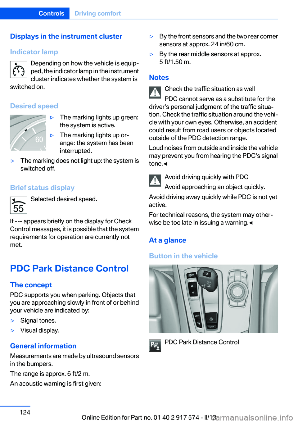
PDC Park Distance Control
Seite 124ControlsDriving comfort124
Online Edition for Part no. 01 40 2 917 574 - II/13
Page 125 of 224
Switching on/off
Switching on automatically
Select transmission position R with the engine
running.
Automatic deactivation during forward
travel
The system switches off when a certain driving
distance or speed is exceeded.
Switch the system back on if necessary.
Switching on/off manually Press the button.‚Ė∑On: the LED lights up.‚Ė∑Off: the LED goes out.
In addition to the PDC Park Distance Control, the
backup camera, refer to page 126, can be
switched on.
Switching on the backup camera via the
iDrive
With PDC activated:
"Rear view camera"
The backup camera image is displayed. The set‚Äź
ting is stored for the remote control currently in
use.
Display
Signal tones
When approaching an object, an intermittent
tone is sounded that indicates the position of the
object. For example, if an object is detected to
the left rear of the vehicle, a signal tone sounds
from the left rear speaker.
The shorter the distance to the object becomes,
the shorter the intervals.
If the distance to a detected object is less than
approx. 10 in/25 cm, a continuous tone is
sounded.
If objects are located both in front of and behind
the vehicle, an alternating continuous signal is
sounded.
The intermittent tone is interrupted after approx.
3 seconds:‚Ė∑If the vehicle stops in front of an object that
is detected by only one of the corner sen‚Äź
sors.‚Ė∑If moving parallel to a wall.
The signal tone is switched off:
‚Ė∑When the vehicle moves away from an ob‚Äź
ject by more than approx. 4 in/10 cm.‚Ė∑When transmission position P is engaged.
Volume
The volume of the PDC signal can be adjusted,
refer to user's manual for Navigation, Entertain‚Äź
ment and Communication.
The setting is stored for the remote control cur‚Äź
rently in use.
Visual warning
The approach of the vehicle to an object can be
shown on the Control Display. Objects that are
farther away are displayed on the Control Dis‚Äź
play before a signal tone sounds.
A display appears as soon as Park Distance
Control (PDC) is activated.
The range of the sensors is represented in col‚Äź
ors: red, green and yellow.
If the backup camera image was selected last, it
again appears on the display. To switch to PDC:
1. "Rear view camera" Select the symbol
on the Control Display.2.Press the controller.
The setting is stored for the remote control cur‚Äź
rently in use.
Seite 125Driving comfortControls125
Online Edition for Part no. 01 40 2 917 574 - II/13
Page 126 of 224
System limits
Limits of ultrasonic measurement
The detection of objects can reach the physical
limits of ultrasonic measurement, e.g.:‚Ė∑With tow bars and trailer hitches.‚Ė∑With thin or wedge-shaped objects.‚Ė∑With low objects.‚Ė∑With objects with corners and sharp edges.
Low objects already displayed, e.g., curbs, can
move into the blind area of the sensors before or
after a continuous tone sounds.
High, protruding objects such as ledges may not
be detected.
False warnings
PDC may issue a warning under the following
conditions even though there is no obstacle
within the detection range:
‚Ė∑In heavy rain.‚Ė∑When sensors are very dirty or covered in
ice.‚Ė∑When sensors are covered in snow.‚Ė∑On rough road surfaces.‚Ė∑In large buildings with right angles and
smooth walls, e.g., in underground garages.‚Ė∑In heavy exhaust.‚Ė∑Due to other ultrasound sources, e.g.,
sweeping machines, high pressure steam
cleaners or neon lights.
Malfunction
A Check Control message is displayed.
The range of the sensors is shown as a shaded
area on the Control Display.
PDC has failed. Have the system checked.
To ensure full operability:
‚Ė∑Keep the sensors clean and free of ice.‚Ė∑When using high-pressure washers, do not
spray the sensors for long periods and main‚Äź
tain a distance of at least 12 in/30 cm.Surround View
The concept
Surround View comprises various camera as‚Äź
sistance systems that help the driver when park‚Äź
ing, maneuvering, and at complex exits and in‚Äź
tersections.‚Ė∑Backup camera, refer to page 126‚Ė∑Side View, refer to page 130.‚Ė∑Top View, refer to page 129.
Backup camera
The concept
The backup camera provides assistance in park‚Äź
ing and maneuvering backwards. The area be‚Äź
hind the vehicle is shown on the Control Display.
Notes Check the traffic situation as well
Check the traffic situation around the ve‚Äź
hicle with your own eyes. Otherwise, an accident
could result from road users or objects located
outside the picture area of the backup camera. ‚óÄ
At a glance
Button in the vehicle
Backup camera
Seite 126ControlsDriving comfort126
Online Edition for Part no. 01 40 2 917 574 - II/13
Page 132 of 224
System limits
The cameras capture a maximum range of
330 ft/100 m.
Parking assistant
The concept
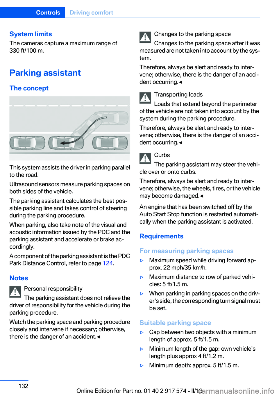
This system assists the driver in parking parallel
to the road.
Ultrasound sensors measure parking spaces on
both sides of the vehicle.
The parking assistant calculates the best pos‚Äź
sible parking line and takes control of steering
during the parking procedure.
When parking, also take note of the visual and
acoustic information issued by the PDC and the
parking assistant and accelerate or brake ac‚Äź
cordingly.
A component of the parking assistant is the PDC
Park Distance Control, refer to page 124.
Notes Personal responsibility
The parking assistant does not relieve the
driver of responsibility for the vehicle during the
parking procedure.
Watch the parking space and parking procedure
closely and intervene if necessary; otherwise,
there is the danger of an accident.‚óÄ
Changes to the parking space
Changes to the parking space after it was
measured are not taken into account by the sys‚Äź
tem.
Therefore, always be alert and ready to inter‚Äź
vene; otherwise, there is the danger of an acci‚Äź
dent occurring.‚óÄ
Transporting loads
Loads that extend beyond the perimeter
of the vehicle are not taken into account by the
system during the parking procedure.
Therefore, always be alert and ready to inter‚Äź
vene; otherwise, there is the danger of an acci‚Äź
dent occurring.‚óÄ
Curbs
The parking assistant may steer the vehi‚Äź
cle over or onto curbs.
Therefore, always be alert and ready to inter‚Äź
vene; otherwise, the wheels, tires, or the vehicle
may become damaged.‚óÄ
An engine that has been switched off by the
Auto Start Stop function is restarted automati‚Äź
cally when the parking assistant is activated.
Requirements
For measuring parking spaces‚Ė∑Maximum speed while driving forward ap‚Äź
prox. 22 mph/35 km/h.‚Ė∑Maximum distance to row of parked vehi‚Äź
cles: 5 ft/1.5 m.‚Ė∑When parking in parking spaces on the driv‚Äź
er's side, the corresponding turn signal must
be set.
Suitable parking space
‚Ė∑Gap between two objects with a minimum
length of approx. 5 ft/1.5 m.‚Ė∑Minimum length of the gap: own vehicle's
length plus approx 4 ft/1.2 m.‚Ė∑Minimum depth: approx. 5 ft/1.5 m.Seite 132ControlsDriving comfort132
Online Edition for Part no. 01 40 2 917 574 - II/13
Page 133 of 224
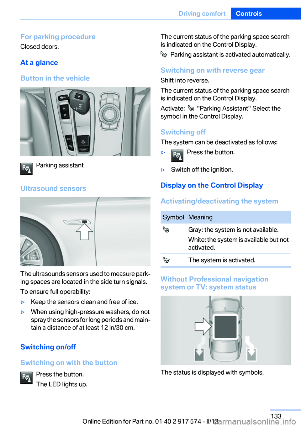
For parking procedure
Closed doors.
At a glance
Button in the vehicle
Parking assistant
Ultrasound sensors
The ultrasounds sensors used to measure park‚Äź
ing spaces are located in the side turn signals.
To ensure full operability:
‚Ė∑Keep the sensors clean and free of ice.‚Ė∑When using high-pressure washers, do not
spray the sensors for long periods and main‚Äź
tain a distance of at least 12 in/30 cm.
Switching on/off
Switching on with the button Press the button.
The LED lights up.
The current status of the parking space search
is indicated on the Control Display.
Parking assistant is activated automatically.
Switching on with reverse gear
Shift into reverse.
The current status of the parking space search
is indicated on the Control Display.
Activate:
"Parking Assistant" Select the
symbol in the Control Display.
Switching off
The system can be deactivated as follows:
‚Ė∑Press the button.‚Ė∑Switch off the ignition.
Display on the Control Display
Activating/deactivating the system
SymbolMeaning Gray: the system is not available.
White: the system is available but not
activated. The system is activated.
Without Professional navigation
system or TV: system status
The status is displayed with symbols.
Seite 133Driving comfortControls133
Online Edition for Part no. 01 40 2 917 574 - II/13
Page 135 of 224
‚Ė∑ " Parking Assistant" Select the symbol on
the Control Display.‚Ė∑Press the button.
Interrupting automatically
The system is interrupted automatically in the
following situations:
‚Ė∑If the driver grasps the steering wheel or if
he takes over steering.‚Ė∑If a gear is selected that does not match the
instruction on the Control Display.‚Ė∑If a turn signal is activated in the opposite
direction to the desired side for parking.‚Ė∑If the vehicle speed exceeds approx.
6 mph/10 km/h.‚Ė∑On snow-covered or slippery road surfaces
if necessary.‚Ė∑If doors are open.‚Ė∑If a maximum number of parking attempts or
the time taken for parking is exceeded.
A Check Control message is displayed.
Resume
An interrupted parking procedure can be con‚Äź
tinued if necessary.
Follow the instructions on the Control Display to
do this.
System limits
No parking assistance
The parking assistant does not offer assistance
in the following situations:
‚Ė∑In tight curves.
Functional limitations
The system may not be fully functional in the
following situations:
‚Ė∑When sensors are dirty or iced over.‚Ė∑In heavy fog, rain or snowfall.‚Ė∑On bumpy road surfaces such as gravel
roads.‚Ė∑When leaves or snow has collected in the
parking space.
Limits of ultrasonic measurement
The detection of objects can reach the physical
limits of ultrasonic measurement, e.g., in the fol‚Äź
lowing circumstances:
‚Ė∑With tow bars and trailer hitches.‚Ė∑With thin or wedge-shaped objects.‚Ė∑With elevated, protruding objects such as
ledges or cargo.‚Ė∑With objects with corners and sharp edges.‚Ė∑With objects with a fine surface structure,
such as fences.
Low objects already displayed, e.g., curbs, can
move into the blind area of the sensors before or
after a continuous tone sounds.
High, protruding objects such as ledges may not
be detected.
The parking assistant may identify parking
spaces that are not suitable for parking.
Malfunction
A Check Control message is displayed.
The parking assistant failed. Have the system
checked.
Seite 135Driving comfortControls135
Online Edition for Part no. 01 40 2 917 574 - II/13
Page 139 of 224
Climate control functions in detail
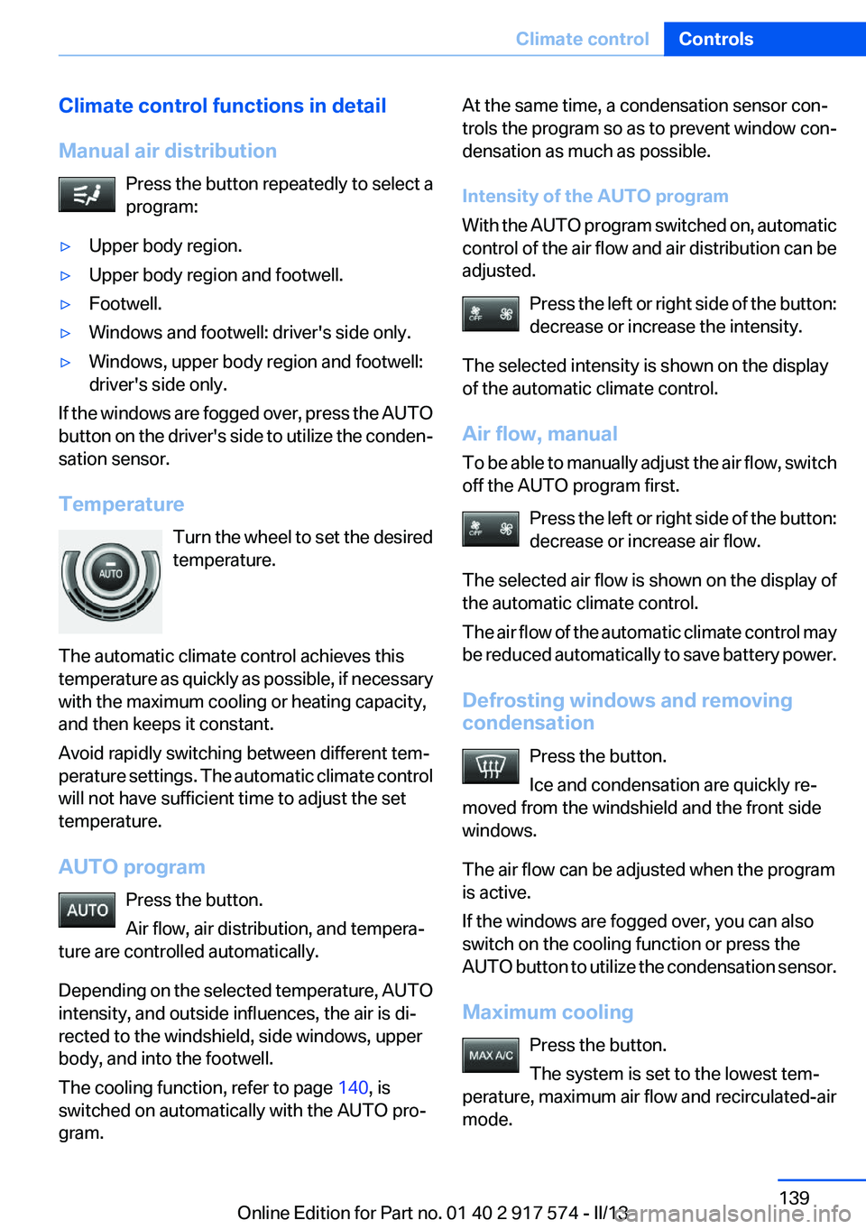
Manual air distribution Press the button repeatedly to select a
program:‚Ė∑Upper body region.‚Ė∑Upper body region and footwell.‚Ė∑Footwell.‚Ė∑Windows and footwell: driver's side only.‚Ė∑Windows, upper body region and footwell:
driver's side only.
If the windows are fogged over, press the AUTO
button on the driver's side to utilize the conden‚Äź
sation sensor.
Temperature Turn the wheel to set the desired
temperature.
The automatic climate control achieves this
temperature as quickly as possible, if necessary
with the maximum cooling or heating capacity,
and then keeps it constant.
Avoid rapidly switching between different tem‚Äź
perature settings. The automatic climate control
will not have sufficient time to adjust the set
temperature.
AUTO program Press the button.
Air flow, air distribution, and tempera‚Äź
ture are controlled automatically.
Depending on the selected temperature, AUTO
intensity, and outside influences, the air is di‚Äź
rected to the windshield, side windows, upper
body, and into the footwell.
The cooling function, refer to page 140, is
switched on automatically with the AUTO pro‚Äź
gram.
At the same time, a condensation sensor con‚Äź
trols the program so as to prevent window con‚Äź
densation as much as possible.
Intensity of the AUTO program
With the AUTO program switched on, automatic
control of the air flow and air distribution can be
adjusted.
Press the left or right side of the button:
decrease or increase the intensity.
The selected intensity is shown on the display
of the automatic climate control.
Air flow, manual
To be able to manually adjust the air flow, switch
off the AUTO program first.
Press the left or right side of the button:
decrease or increase air flow.
The selected air flow is shown on the display of
the automatic climate control.
The air flow of the automatic climate control may
be reduced automatically to save battery power.
Defrosting windows and removing
condensation
Press the button.
Ice and condensation are quickly re‚Äź
moved from the windshield and the front side
windows.
The air flow can be adjusted when the program
is active.
If the windows are fogged over, you can also
switch on the cooling function or press the
AUTO button to utilize the condensation sensor.
Maximum cooling Press the button.
The system is set to the lowest tem‚Äź
perature, maximum air flow and recirculated-air
mode.Seite 139Climate controlControls139
Online Edition for Part no. 01 40 2 917 574 - II/13
Page 140 of 224
Air flows out of the vents for the upper body re‚Äź
gion. The vents need to be open for this.
Air is cooled as quickly as possible:‚Ė∑At an external temperature of approx.
32 ‚ĄČ/0 ‚ĄÉ.‚Ė∑When the engine is running or when electri‚Äź
cal drive readiness is indicated.
The air flow can be adjusted when the program
is active.
Automatic recirculated-air control/
recirculated-air mode
You can respond to unpleasant odors or pollu‚Äź
tants in the immediate environment by tempo‚Äź
rarily suspending the supply of outside air. The
system then recirculates the air currently within
the vehicle.
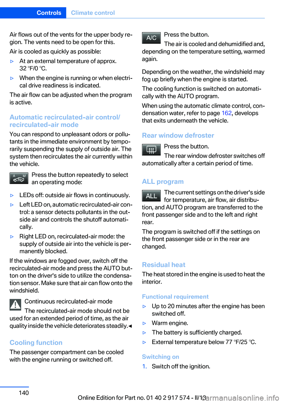
Press the button repeatedly to select
an operating mode:
‚Ė∑LEDs off: outside air flows in continuously.‚Ė∑Left LED on, automatic recirculated-air con‚Äź
trol: a sensor detects pollutants in the out‚Äź
side air and controls the shutoff automati‚Äź
cally.‚Ė∑Right LED on, recirculated-air mode: the
supply of outside air into the vehicle is per‚Äź
manently blocked.
If the windows are fogged over, switch off the
recirculated-air mode and press the AUTO but‚Äź
ton on the driver's side to utilize the condensa‚Äź
tion sensor. Make sure that air can flow onto the
windshield.
Continuous recirculated-air mode
The recirculated-air mode should not be
used for an extended period of time, as the air
quality inside the vehicle deteriorates steadily. ‚óÄ
Cooling function
The passenger compartment can be cooled
with the engine running or switched off.
Press the button.
The air is cooled and dehumidified and,
depending on the temperature setting, warmed
again.
Depending on the weather, the windshield may
fog up briefly when the engine is started.
The cooling function is switched on automati‚Äź
cally with the AUTO program.
When using the automatic climate control, con‚Äź
densation water, refer to page 162, develops
that exits underneath the vehicle.
Rear window defroster Press the button.
The rear window defroster switches off
automatically after a certain period of time.
ALL program The current settings on the driver's side
for temperature, air flow, air distribu‚Äź
tion, and AUTO program are transferred to the
front passenger side and to the left and right
rear.
The program is switched off if the settings on
the front passenger side or in the rear are
changed.
Residual heat
The heat stored in the engine is used to heat the
interior.
Functional requirement‚Ė∑Up to 20 minutes after the engine has been
switched off.‚Ė∑Warm engine.‚Ė∑The battery is sufficiently charged.‚Ė∑External temperature below 77 ‚ĄČ/25 ‚ĄÉ.
Switching on
1.Switch off the ignition.Seite 140ControlsClimate control140
Online Edition for Part no. 01 40 2 917 574 - II/13
Page 188 of 224
MaintenanceVehicle equipment
All standard, country-specific and optional
equipment that is offered in the model series is
described in this chapter. Therefore, equipment
is also described that is not available in a vehicle,
e. g., because of the selected optional equip‚Äź
ment or country variant. This also applies for
safety-related functions and systems.
BMW Maintenance System
The maintenance system directs you to re‚Äź
quired maintenance measures and thereby sup‚Äź
ports you in maintaining road safety and the op‚Äź
erational reliability of the vehicle.
Condition Based Service CBS
Sensors and special algorithms take into ac‚Äź
count the driving conditions of your vehicle.
Based on this, Condition Based Service deter‚Äź
mines the maintenance requirements.
The system makes it possible to adapt the
amount of maintenance you need to your user
profile.
Details on the service requirements, refer to
page 86, can be displayed on the Control Dis‚Äź
play.
Service data in the remote control
Information on the required maintenance is con‚Äź
tinuously stored in the remote control. Your
service center will read out this data and suggest
the right array of service procedures for your ve‚Äź
hicle.
Therefore, hand your service specialist the re‚Äź
mote control that you used most recently.Storage periods
Storage periods during which the vehicle bat‚Äź
tery was disconnected are not taken into ac‚Äź
count.
If this occurs, have a service center update the
time-dependent maintenance procedures,
such as checking brake fluid and, if necessary,
changing the engine oil and the microfilter/acti‚Äź
vated-charcoal filter.
Service and Warranty
Information Booklet for US
models and Warranty and
Service Guide Booklet for
Canadian models
Please consult your Service and Warranty Infor‚Äź
mation Booklet for US models and Warranty and
Service Guide Booklet for Canadian models for
additional information on service requirements.
Maintenance and repair should be performed by
your service center. Make sure to have regular
maintenance procedures recorded in the vehi‚Äź
cle's Service and Warranty Information Booklet
for US models, and in the Warranty and Service
Guide Booklet for Canadian models. These en‚Äź
tries are proof of regular maintenance.Seite 188MobilityMaintenance188
Online Edition for Part no. 01 40 2 917 574 - II/13
Page 204 of 224
CareVehicle equipment
All standard, country-specific and optional
equipment that is offered in the model series is
described in this chapter. Therefore, equipment
is also described that is not available in a vehicle,
e. g., because of the selected optional equip‚Äź
ment or country variant. This also applies for
safety-related functions and systems.
Car washes
Hints Steam jets or high-pressure washers
When using steam jets or high-pressure
washers, hold them a sufficient distance away
and use a maximum temperature of
140 ‚ĄČ/60 ‚ĄÉ.
Ensure that a distance of at least 31.5 in‚Äź
ches/80 cm from the glass sunroof is maintained
at all times. Holding them too close or using ex‚Äź
cessively high pressures or temperatures can
cause damage or preliminary damage that may
then lead to long-term damage.
Follow the user's manual for the high-pressure
washer.‚óÄ
Cleaning sensors/cameras with high-
pressure washers
When using high-pressure washers, do not
spray the exterior sensors and cameras, e.g.,
Park Distance Control, for extended periods of
time and only from a distance of at least
12 in/30 cm.‚óÄ
Regularly remove foreign items such as leaves
in the area below the windshield when the hood
is raised.
Wash your vehicle frequently, particularly in win‚Äź
ter.Intense soiling and road salt can damage the ve‚Äź
hicle.
Automatic car washes
Notes
Note the following:‚Ė∑Give preference to cloth car washes or those
that use soft brushes in order to avoid paint
damage.‚Ė∑Make sure that the wheels and tires are not
damaged by the transport mechanisms.‚Ė∑Fold in the exterior mirrors; otherwise, they
may be damaged, depending on the width of
the vehicle.‚Ė∑Deactivate the rain sensor, refer to
page 74,to avoid unintentional wiper activa‚Äź
tion.‚Ė∑In some cases, an unintentional alarm can be
triggered by the interior motion sensor of the
alarm system. Follow the instructions on
avoiding an unintentional alarm, refer to
page 47.
Guide rails in car washes
Avoid car washes with guide rails higher
than 4 in/10 cm; otherwise, the vehicle body
could be damaged.‚óÄ
Before driving into a car wash
In order to ensure that the vehicle can roll in a car
wash, take the following steps:
Automatic transmission:
1.Release parking brake, refer to page 70, and
deactivate Automatic Hold, refer to
page 71.2.Drive into the car wash.3.Depress the brake pedal as needed.Seite 204MobilityCare204
Online Edition for Part no. 01 40 2 917 574 - II/13