BMW CONVERTIBLE 1998 Owners Manual
Manufacturer: BMW, Model Year: 1998, Model line: CONVERTIBLE, Model: BMW CONVERTIBLE 1998Pages: 179, PDF Size: 3.51 MB
Page 151 of 179
15 0
Removal and installationa
Do not disconnect the battery
cable from its terminal while the engine
is running, as the resulting voltage surge
would destroy the vehicle's electronic
systems.c
When disconnecting, start with the neg-
ative terminal, then proceed to the pos-
itive side. Unscrew the battery retaining
clamp.
When installing the battery, connect the
positive terminal first, then proceed to
the negative pole.
a
When installing, always ensure that
the battery is properly mounted.
Otherwise it will not be sufficiently
secured in an accident.c
Charging the battery Always ensure that the engine is off
before recharging an installed battery. a
To avoid short circuits, always
disconnect the cable from the battery's
negative terminal before working on the
electrical system.cOn vehicles with a connecting point in
the engine compartment, it is easiest to
charge the battery by using this con-
necting point (positive pole), and a
ground in the engine compartment
(refer to "Jump-starting" on page 15 3).
If you are planning to remove the vehi-
cle from service for more than four
weeks, you should disconnect the bat-
tery at the negative terminal.
If you intend to store your car for longer
than six weeks: remove the battery,
charge it and store it in a cool (but frost-
free) room. Recharge the battery after
three months at the latest, as it will oth-
erwise be damaged beyond use. Every
time the battery is discharged, espe-
cially over extended periods, its service
life is reduced.
A
Bring used batteries to an autho-
rized collection point or a BMW Re-
tailer. Always maintain the battery in an
upright position for transport and stor-
age. Secure the battery against tilting
when transporting.c
a
Storage periods during which the
battery is disconnected are not taken
into consideration by the Service Inter-
val Display for changing the brake fluid.
Therefore, make sure that the brake fluid
is changed every two years at the latest,
regardless of the display. Additional
notes: refer to page 128.c
Battery
Page 152 of 179
15 1
At a glanceControlsCar careRepairsTechnicalDataIndex
If an electrical device fails, switch it off
and check the fuse.
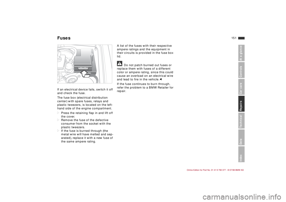
The fuse box (electrical distribution
center) with spare fuses, relays and
plastic tweezers, is located on the left-
hand side of the engine compartment.
dPress the retaining flap in and lift off
the cover.
dRemove the fuse of the defective
consumer from the socket with the
plastic tweezers.
dIf the fuse is burned through (the
metal wire will have melted and sep-
arated), replace it with a new fuse of
the same ampere rating.A list of the fuses with their respective
ampere ratings and the equipment in
their circuits is provided in the fuse box
lid.
a
Do not patch burned out fuses or
replace them with fuses of a different
color or ampere rating, since this could
cause an overload on an electrical wire
and lead to fire in the vehicle.c
If the fuse continues to burn through,
refer the problem to a BMW Retailer for
repair.
360de102Fuses
Page 153 of 179
15 2
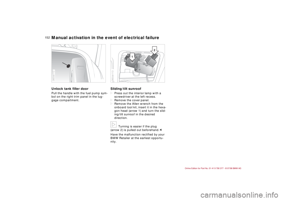
Unlock tank filler door Pull the handle with the fuel pump sym-
bol on the right trim panel in the lug-
gage compartment.
Sliding/tilt sunroof dPress out the interior lamp with a
screwdriver at the left recess.
dRemove the cover panel.
dRemove the Allen wrench from the
onboard tool kit, insert it in the hexa-
gon head (arrow 1) and turn the slid-
ing/tilt sunroof in the desired
direction.b
Turning is easier if the plug
(arrow 2) is pulled out beforehand.c
Have the malfunction rectified by your
BMW Retailer at the earliest opportu-
nity.
360de112
2
1
360de113
Manual activation in the event of electrical failure
Page 154 of 179
15 3
At a glanceControlsCar careRepairsTechnicalDataIndex
Never use spray starter fluids to start
the engine.
When the battery is discharged, you
can use two jumper cables to start your
car with power from the battery in a
second vehicle. Always use jumper
cables with fully insulated handles on
the terminal clamps.a
When the engine is running, con-
tact with electrical conductors and com-
ponents is dangerous and can be fatal.c
Carefully observe the following instruc-
tions to avoid personal injury as well as
damage to one or both vehicles:
1 Ensure that the battery on the sup-
port vehicle is also rated at 12 volts,
and that the capacity (Ah) is roughly
comparable (printed on casing).
2 Leave your battery connected to the
car's electrical system.
3 The bodies of the two vehicles must
not touch, or a short circuit could
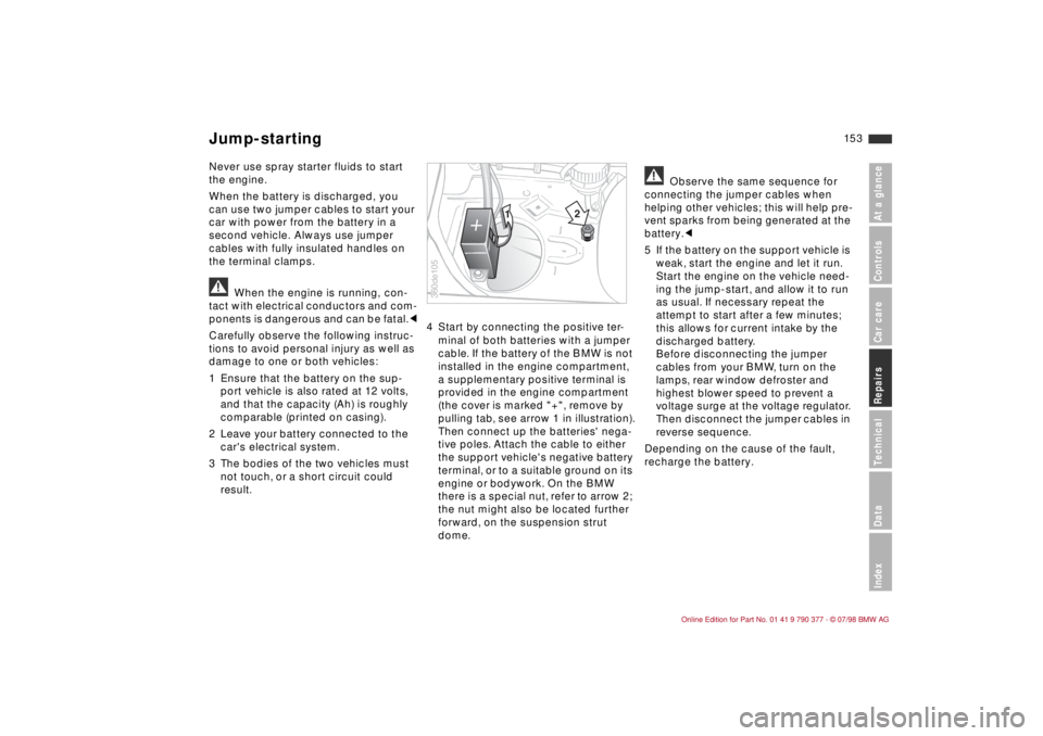
result.4 Start by connecting the positive ter-
minal of both batteries with a jumper
cable. If the battery of the BMW is not
installed in the engine compartment,
a supplementary positive terminal is
provided in the engine compartment
(the cover is marked "+", remove by
pulling tab, see arrow 1 in illustration).
Then connect up the batteries' nega-
tive poles. Attach the cable to either
the support vehicle's negative battery
terminal, or to a suitable ground on its
engine or bodywork. On the BMW
there is a special nut, refer to arrow 2;
the nut might also be located further
forward, on the suspension strut
dome.
a
Observe the same sequence for
connecting the jumper cables when
helping other vehicles; this will help pre-
vent sparks from being generated at the
battery.c
5 If the battery on the support vehicle is
weak, start the engine and let it run.
Start the engine on the vehicle need-
ing the jump-start, and allow it to run
as usual. If necessary repeat the
attempt to start after a few minutes;
this allows for current intake by the
discharged battery.
Before disconnecting the jumper
cables from your BMW, turn on the
lamps, rear window defroster and
highest blower speed to prevent a
voltage surge at the voltage regulator.
Then disconnect the jumper cables in
reverse sequence.
Depending on the cause of the fault,
recharge the battery.
12
360de105
Jump-starting
Page 155 of 179
15 4
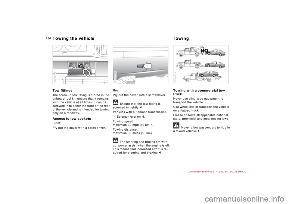
Tow fittingsThe screw-in tow fitting is stored in the
onboard tool kit; ensure that it remains
with the vehicle at all times. It can be
screwed in to either the front or the rear
of the vehicle and is intended for towing
only on a roadway. Access to tow socketsFront:
Pry out the cover with a screwdriver.Rear:
Pry out the cover with a screwdriver.
a
Ensure that the tow fitting is
screwed in tightly.c
Vehicles with automatic transmission:
dSelector lever on N.
Towing speed:
maximum 30 mph (50 km/h).
Towing distance:
maximum 30 miles (50 km).
a
The steering and brakes are with-
out power assist when the engine is off.
This means that increased effort is re-
quired for steering and braking.c
Towing with a commercial tow
truckNever use sling-type equipment to
transport the vehicle.
Use wheel lifts or transport the vehicle
on a flatbed truck.
Please observe all applicable national,
state, provincial and local towing laws.a
Never allow passengers to ride in
a towed vehicle.c
360de103
360de104
360us128
Towing the vehicle Towing
Page 156 of 179
At a glance
Controls and featuresCare and maintenanceAdvanced technology
Technical data
Owner service procedure
At a glanceControls Car careRepairsTechnicalDataIndex
Index
15 5
Airbags156
Automatic Stability Control
plus Traction (ASC+T)156
Radio reception157
Safety belt tensioner157
Page 157 of 179
15 6
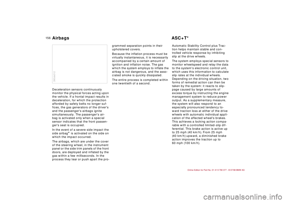
Deceleration sensors continuously
monitor the physical forces acting upon
the vehicle. If a frontal impact results in
deceleration, for which the protection
afforded by safety belts no longer suf-
fices, the gas generators of the driver's
and the passenger's airbags ignite
simultaneously. The passenger's air-
bag is activated only when a special
sensor indicates that the front passen-
ger's seat is occupied.
In the event of a severe side impact the
side airbag
* is activated on the side on
which the impact occurred.
The airbags, which are under the cover
of the steering wheel, in the instrument
panel or the side trim panels of the front
doors, are deployed and inflated by the
gas within a few milliseconds. In the
process they tear or push apart the pro-grammed separation points in their
upholstered covers.
Because the inflation process must be
virtually instantaneous, it is necessarily
accompanied by a certain amount of
ignition and inflation noise. The gas
which the system employs to inflate the
airbag is not dangerous, and the asso-
ciated smoke is quickly dissipated.
The entire process is completed within
one twentieth of a second.Automatic Stability Control plus Trac-
tion helps maintain stable and con-
trolled vehicle response by inhibiting
slip at the drive wheels.
The system employs special sensors to
monitor wheelspeed and relay the data
to the system's electronic control unit,
which uses this information to calculate
slip rates at the individual wheels.
Depending on the driving situation, two
forms of remedial action can then be
taken by the system: it reacts to slip-
page caused by large amounts of
excess torque by instructing the engine
management system to reduce power
output. As a supplementary measure,
the system will also respond to an
especially pronounced tendency to-
ward traction loss at either of the drive
wheels with automatic individual appli-
cation of the affected wheel's brakes.
This achieves a locking action compa-
rable with a controlled limited-slip dif-
ferential. This brake action is active up
to 25 mph (40 km/h). From 25 mph
(40 km/h) upward, a diminished brake
action improves the traction up to
60 mph (100 km/h).
390de012Airbags ASC+T*
Page 158 of 179
15 7
At a glanceControls Car careRepairsTechnicalDataIndex
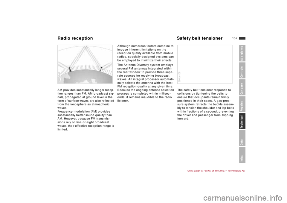
AM provides substantially longer recep-
tion ranges than FM. AM broadcast sig-
nals, propagated at ground level in the
form of surface waves, are also reßected
from the ionosphere as atmospheric
waves.
Frequency-modulation (FM) provides
substantially better sound quality than
AM. However, because FM transmis-
sions rely on line-of-sight broadcast
waves, their effective reception range is
limited. Although numerous factors combine to
impose inherent limitations on the
reception quality available from mobile
radios, specially designed systems can
be employed to minimize their effects:
The Antenna Diversity system employs
several FM antennas integrated within
the rear window to provide three sepa-
rate sources for receiving broadcast
waves. An integral processor automati-
cally selects the antenna with the best
FM reception quality at any given time.
Because the ongoing antenna selection
process is completed within millisec-
onds, it remains inaudible to the radio
listener. The safety belt tensioner responds to
collisions by tightening the belts to
ensure that occupants remain firmly
positioned in their seats. A gas-pres-
sure system retracts the buckle assem-
bly to tension the shoulder and lap belts
within fractions of a second, preventing
the driver and passenger from slipping
forward.360de084
390de108
Radio reception Safety belt tensioner
Page 159 of 179

15 8
Page 160 of 179
At a glance
Controls and featuresCare and maintenanceAdvanced technology
Technical data
Owner service procedure
At a glanceControls Car careRepairsTechnicalDataIndex
Index
15 9
Engine specifications 160
Dimensions 161
Weights 163
Capacities 166
Electrical system 167
Drive belts 167