turn signal BMW I3 2014 I01 User Guide
[x] Cancel search | Manufacturer: BMW, Model Year: 2014, Model line: I3, Model: BMW I3 2014 I01Pages: 230, PDF Size: 29.93 MB
Page 92 of 230
Blue lights
High beams High beams are activated.
For additional information, refer to High
beams, refer to page 70.
General lamps Check Control At least one Check Control message is
displayed or is stored (symbol in dis‐
play).
Text messages Text messages in combination with a symbol
in the instrument cluster explain a Check Con‐
trol message and the meaning of the indicator
and warning lights.
Supplementary text messages
Additional information, such as on the cause of
an error or the required action, can be called up
via Check Control.
With urgent messages the added text will be
automatically displayed on the Control Display.
Symbols Depending on the Check Control message, the
following functions can be selected.▷ "Owner's Manual"
Display additional information about the
Check Control message in the Integrated
Owner's Manual.▷ "Service request"
Contact your service center.▷ "Roadside Assistance"
Contact Roadside Assistance.Hiding Check Control messages
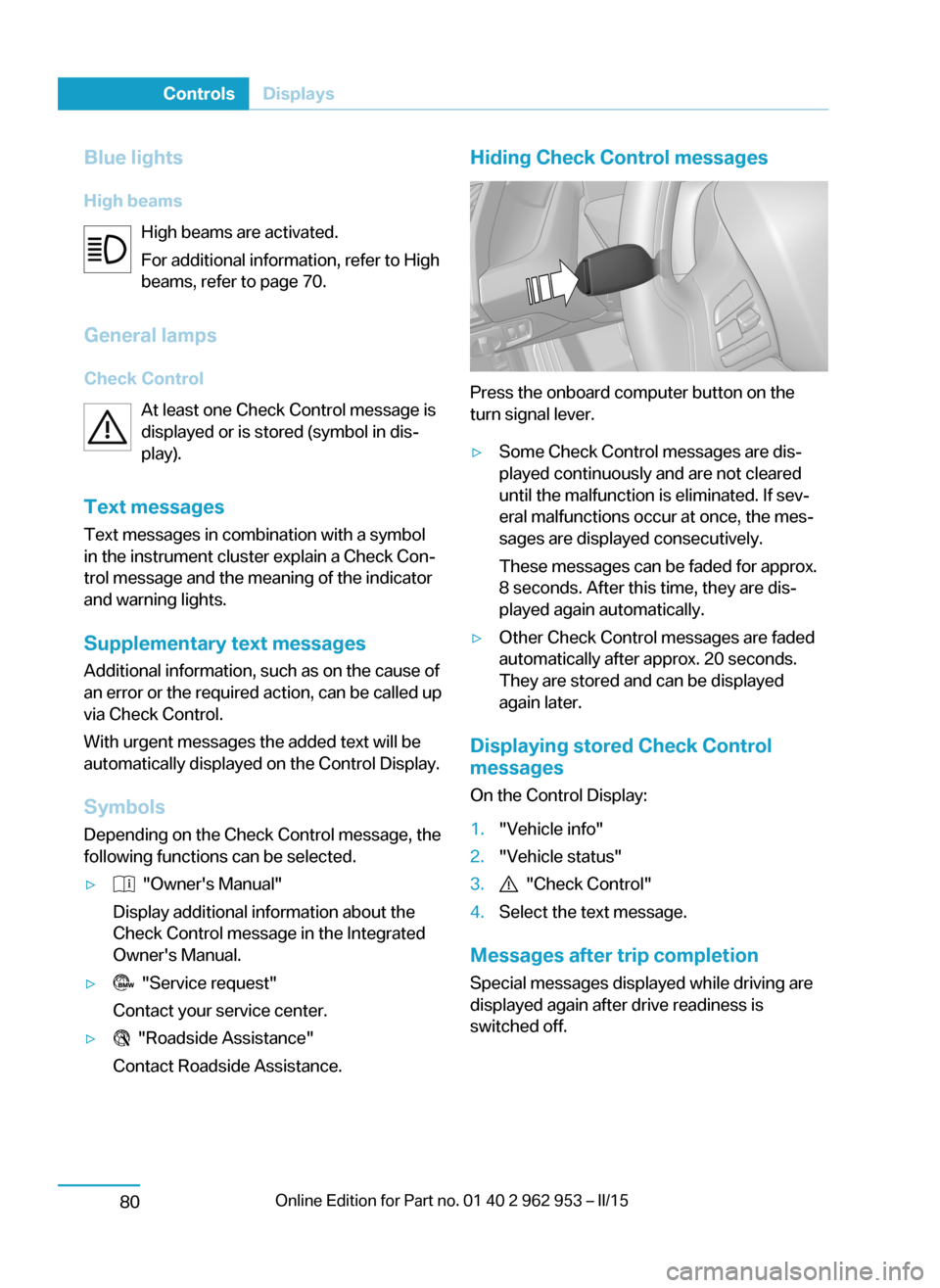
Press the onboard computer button on the
turn signal lever.
▷Some Check Control messages are dis‐
played continuously and are not cleared
until the malfunction is eliminated. If sev‐
eral malfunctions occur at once, the mes‐
sages are displayed consecutively.
These messages can be faded for approx.
8 seconds. After this time, they are dis‐
played again automatically.▷Other Check Control messages are faded
automatically after approx. 20 seconds.
They are stored and can be displayed
again later.
Displaying stored Check Control
messages
On the Control Display:
1."Vehicle info"2."Vehicle status"3. "Check Control"4.Select the text message.
Messages after trip completion Special messages displayed while driving are
displayed again after drive readiness is
switched off.
Seite 78ControlsDisplays80
Page 93 of 230
With Range Extender: fuel
gauge
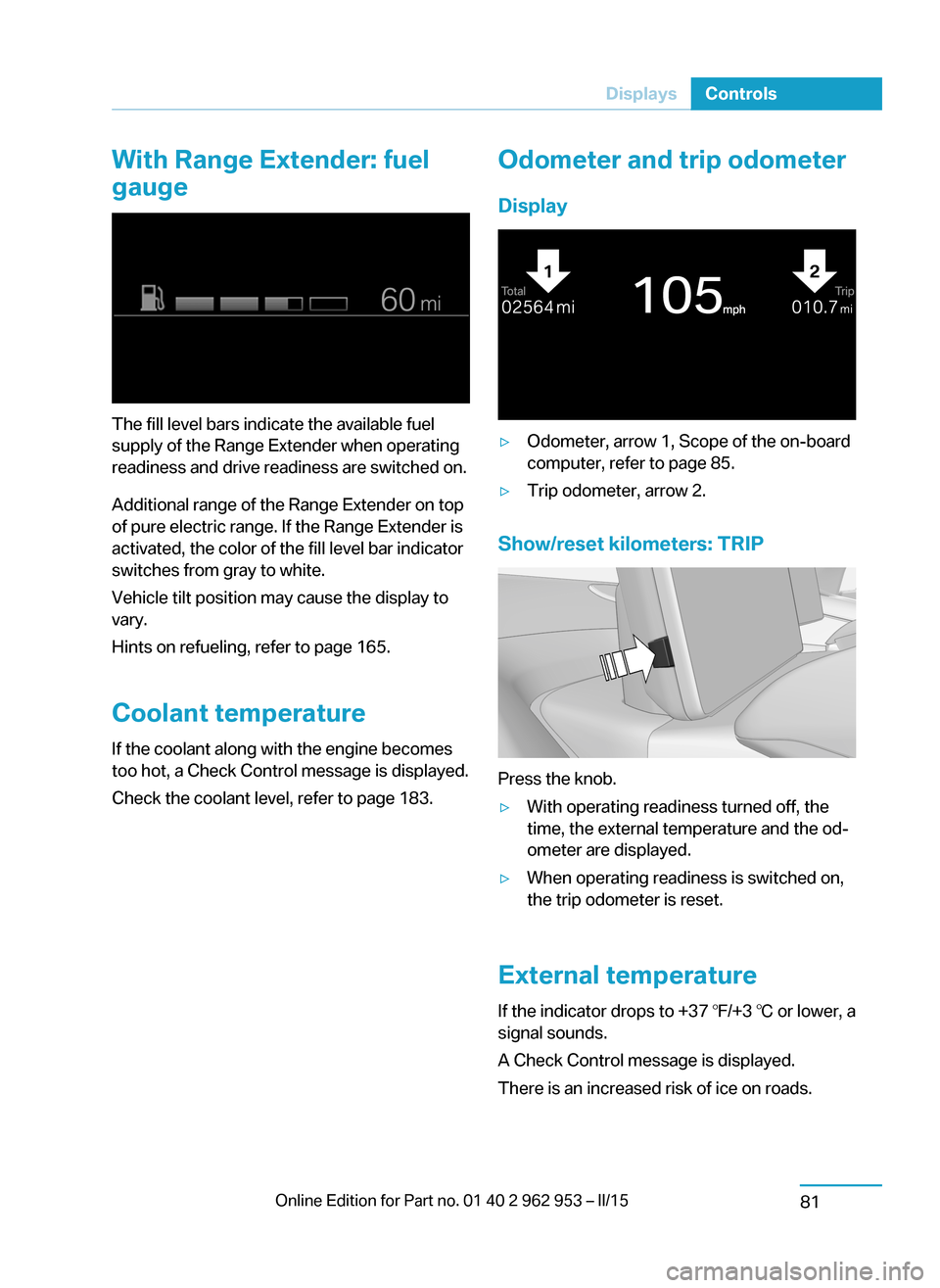
The fill level bars indicate the available fuel
supply of the Range Extender when operating
readiness and drive readiness are switched on.
Additional range of the Range Extender on top
of pure electric range. If the Range Extender is
activated, the color of the fill level bar indicator
switches from gray to white.
Vehicle tilt position may cause the display to
vary.
Hints on refueling, refer to page 165.
Coolant temperature If the coolant along with the engine becomes
too hot, a Check Control message is displayed.
Check the coolant level, refer to page 183.
Odometer and trip odometer
Display▷Odometer, arrow 1, Scope of the on-board
computer, refer to page 85.▷Trip odometer, arrow 2.
Show/reset kilometers: TRIP
Press the knob.
▷With operating readiness turned off, the
time, the external temperature and the od‐
ometer are displayed.▷When operating readiness is switched on,
the trip odometer is reset.
External temperature
If the indicator drops to +37 ℉/+3 ℃ or lower, a
signal sounds.
A Check Control message is displayed.
There is an increased risk of ice on roads.
Seite 79DisplaysControls81
Page 97 of 230
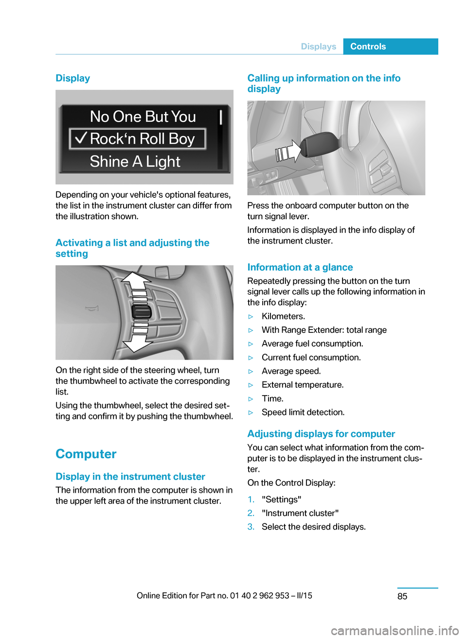
Display
Depending on your vehicle's optional features,
the list in the instrument cluster can differ from
the illustration shown.
Activating a list and adjusting the
setting
On the right side of the steering wheel, turn
the thumbwheel to activate the corresponding
list.
Using the thumbwheel, select the desired set‐
ting and confirm it by pushing the thumbwheel.
Computer
Display in the instrument cluster The information from the computer is shown in
the upper left area of the instrument cluster.
Calling up information on the info
display
Press the onboard computer button on the
turn signal lever.
Information is displayed in the info display of
the instrument cluster.
Information at a glance
Repeatedly pressing the button on the turn
signal lever calls up the following information in
the info display:
▷Kilometers.▷With Range Extender: total range▷Average fuel consumption.▷Current fuel consumption.▷Average speed.▷External temperature.▷Time.▷Speed limit detection.
Adjusting displays for computer
You can select what information from the com‐
puter is to be displayed in the instrument clus‐
ter.
On the Control Display:
1."Settings"2."Instrument cluster"3.Select the desired displays.Seite 83DisplaysControls85
Page 98 of 230
Information in detail
With Range Extender: total range The total range considers the
capacity of the fuel tank as well
as the electric energy in the
high-voltage battery.
Average fuel consumption
The average fuel consumption is calculated on
the basis of various distances. Standstill with
drive readiness turned off is not considered.
Current fuel consumption Displays the current energy consumption. The
efficiency of the driving can be monitored.
Average speed
Periods when vehicle is parked with drive read‐
iness switched off are not included when cal‐
culating average speed.
Resetting average values Press and hold the onboard computer button
on the turn signal lever.
Speed limit detection
Description of the speed limit detection, refer
to page 83, function.
Trip computer
The vehicle features two types of board com‐
puters.▷"Onboard info": the values can be reset as
often as necessary.▷"Trip computer": the values provide an
overview of the current trip.
Resetting the trip computer
On the Control Display:
1."Vehicle info"2."Trip computer"3."Reset": all values are reset.
"Automatically reset": all values are reset
approx. 4 hours after the vehicle came to a
standstill.
Display on the Control Display
Display the computer or trip computer on the
Control Display.
1."Vehicle info"2."Onboard info" or "Trip computer"
Resetting the fuel consumption or
speed
On the Control Display:
1."Vehicle info"2."Onboard info"3."Consumpt." or "Speed"4."Yes"
Speed warning
The concept Displays a speed, when reached, should cause
a warning to be issued.
The warning is repeated if the vehicle speed
drops below the set speed once by at least
3 mph/5 km/h.
Displaying, setting or changing the
speed warning
On the Control Display:
1."Settings"2."Speed"3."Warning at:"4.Turn the controller until the desired speed
is displayed.5.Press the controller.
Speed warning is stored.
Seite 84ControlsDisplays86
Page 113 of 230
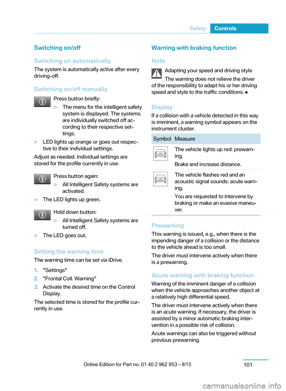
Switching on/off
Switching on automatically The system is automatically active after every
driving-off.
Switching on/off manually Press button briefly:▷The menu for the intelligent safety
system is displayed. The systems
are individually switched off ac‐
cording to their respective set‐
tings.▷LED lights up orange or goes out respec‐
tive to their individual settings.
Adjust as needed. Individual settings are
stored for the profile currently in use.
Press button again:
▷All Intelligent Safety systems are
activated.▷The LED lights up green.
Hold down button:
▷All Intelligent Safety systems are
turned off.▷The LED goes out.
Setting the warning time
The warning time can be set via iDrive.
1."Settings"2."Frontal Coll. Warning"3.Activate the desired time on the Control
Display.
The selected time is stored for the profile cur‐
rently in use.
Warning with braking function
Note Adapting your speed and driving styleThe warning does not relieve the driver
of the responsibility to adapt his or her driving
speed and style to the traffic conditions.◀
Display If a collision with a vehicle detected in this way
is imminent, a warning symbol appears on the
instrument cluster.SymbolMeasureThe vehicle lights up red: prewarn‐
ing.
Brake and increase distance.The vehicle flashes red and an
acoustic signal sounds: acute warn‐
ing.
You are requested to intervene by
braking or make an evasive maneu‐
ver.
Prewarning
This warning is issued, e.g., when there is the
impending danger of a collision or the distance
to the vehicle ahead is too small.
The driver must intervene actively when there
is a prewarning.
Acute warning with braking function
Warning of the imminent danger of a collision
when the vehicle approaches another object at
a relatively high differential speed.
The driver must intervene actively when there
is an acute warning. If necessary, the driver is
assisted by a minor automatic braking inter‐
vention in a possible risk of collision.
Acute warnings can also be triggered without
previous prewarning.
Seite 99SafetyControls101
Page 130 of 230
Monitor your driving, be on the alert, observe
the vehicle surroundings and other traffic and
react when needed - risk of accident.◀
Avoid driving fast with PDC
Avoid approaching an object too fast.
Avoid driving off fast while PDC is not yet ac‐
tive.
For technical reasons, the system may other‐
wise be too late in issuing a warning.◀
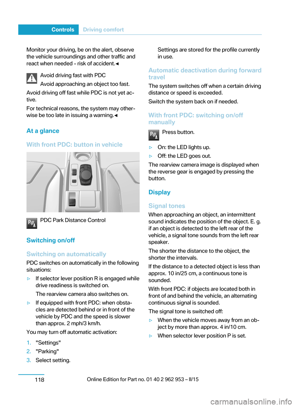
At a glance
With front PDC: button in vehicle
PDC Park Distance Control
Switching on/off
Switching on automatically PDC switches on automatically in the following
situations:
▷If selector lever position R is engaged while
drive readiness is switched on.
The rearview camera also switches on.▷If equipped with front PDC: when obsta‐
cles are detected behind or in front of the
vehicle by PDC and the speed is slower
than approx. 2 mph/3 km/h.
You may turn off automatic activation:
1."Settings"2."Parking"3.Select setting.Settings are stored for the profile currently
in use.
Automatic deactivation during forward
travel
The system switches off when a certain driving
distance or speed is exceeded.
Switch the system back on if needed.
With front PDC: switching on/off
manually
Press button.
▷On: the LED lights up.▷Off: the LED goes out.
The rearview camera image is displayed when
the reverse gear is engaged by pressing the
button.
Display
Signal tones When approaching an object, an intermittent
sound indicates the position of the object. E. g.
if an object is detected to the left rear of the
vehicle, a signal tone sounds from the left rear
speaker.
The shorter the distance to the object, the
shorter the intervals.
If the distance to a detected object is less than
approx. 10 in/25 cm, a continuous tone is
sounded.
With front PDC: if objects are located both in
front of and behind the vehicle, an alternating
continuous signal is sounded.
The signal tone is switched off:
▷When the vehicle moves away from an ob‐
ject by more than approx. 4 in/10 cm.▷When selector lever position P is set.Seite 116ControlsDriving comfort118
Page 201 of 230
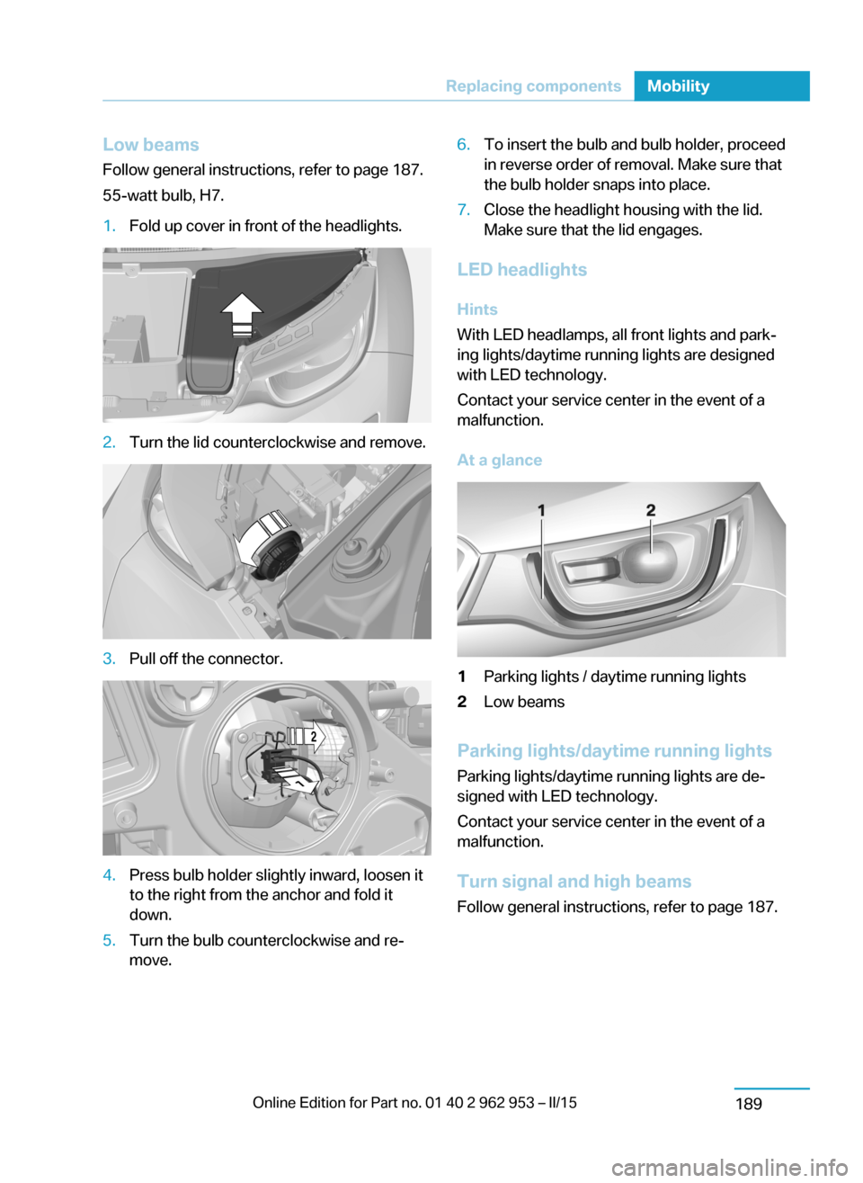
Low beamsFollow general instructions, refer to page 187.
55-watt bulb, H7.1.Fold up cover in front of the headlights.2.Turn the lid counterclockwise and remove.3.Pull off the connector.4.Press bulb holder slightly inward, loosen it
to the right from the anchor and fold it
down.5.Turn the bulb counterclockwise and re‐
move.6.To insert the bulb and bulb holder, proceed
in reverse order of removal. Make sure that
the bulb holder snaps into place.7.Close the headlight housing with the lid.
Make sure that the lid engages.
LED headlights
Hints
With LED headlamps, all front lights and park‐
ing lights/daytime running lights are designed
with LED technology.
Contact your service center in the event of a
malfunction.
At a glance
1Parking lights / daytime running lights2Low beams
Parking lights/daytime running lights
Parking lights/daytime running lights are de‐
signed with LED technology.
Contact your service center in the event of a
malfunction.
Turn signal and high beams Follow general instructions, refer to page 187.
Seite 187Replacing componentsMobility189
Page 202 of 230
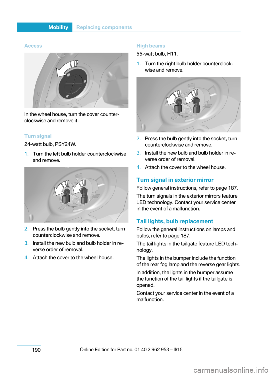
Access
In the wheel house, turn the cover counter‐
clockwise and remove it.
Turn signal
24-watt bulb, PSY24W.
1.Turn the left bulb holder counterclockwise
and remove.2.Press the bulb gently into the socket, turn
counterclockwise and remove.3.Install the new bulb and bulb holder in re‐
verse order of removal.4.Attach the cover to the wheel house.High beams
55-watt bulb, H11.1.Turn the right bulb holder counterclock‐
wise and remove.2.Press the bulb gently into the socket, turn
counterclockwise and remove.3.Install the new bulb and bulb holder in re‐
verse order of removal.4.Attach the cover to the wheel house.
Turn signal in exterior mirror
Follow general instructions, refer to page 187.
The turn signals in the exterior mirrors feature
LED technology. Contact your service center
in the event of a malfunction.
Tail lights, bulb replacement
Follow the general instructions on lamps and
bulbs, refer to page 187.
The tail lights in the tailgate feature LED tech‐
nology.
The lights in the bumper include the function
of the rear fog lamp and the reverse gear lights.
In addition, the lights in the bumper assume
the function of the tail lights if the tailgate is
opened.
Contact your service center in the event of a
malfunction.
Seite 188MobilityReplacing components190
Page 221 of 230
Button, RES 112
Button, Start/Stop 62
Bypassing, refer to Jump- starting 194
C
California Proposition 65 Warning 8
Camera-based Cruise Con‐ trol 109
Camera, care 201
Camera, rearview cam‐ era 120
Can holder, refer to Cuphold‐ ers 139
Car battery 191
Car care products 199
Care, displays 201
Care, vehicle 199
Cargo 148
Cargo area 135
Cargo area, enlarging 136
Cargo area, storage compart‐ ments 140
Cargo cover 135
Cargo, securing 149
Cargo straps, securing cargo 149
Car key, refer to Remote con‐ trol 36
Carpet, care 201
Car wash 198
Catalytic converter, refer to Hot exhaust system 145
CBS Condition Based Serv‐ ice 185
Center armrest 139
Center console 16
Central locking system 42
Central screen, refer to Con‐ trol Display 18
Changes, technical, refer to Safety 7
Changing wheels 191
Changing wheels/tires 173 Charging battery, see Vehicle charging 156
Charging, refer to Charging vehicle 156
Charging, refer to Vehicle charging 156
Charging screen 75
Charging state indicator, high-voltage battery 76
Charging status, see display of the charging status 160
Charging vehicle 156
Charging vehicle, refer to Ve‐ hicle charging 156
Chassis number, see vehicle identification number 10
Check Control 77
Check engine oil 181
Check oil level 181
Children, seating position 58
Children, transporting safely 58
Child restraint fixing sys‐ tem 58
Child restraint fixing system LATCH 59
Child restraint fixing systems, mounting 58
Child seat, mounting 58
Child seats 58
Chrome parts, care 200
Cigarette lighter 134
Cleaning displays 201
Climate control 127, 129
Clock 82
Closing/opening via door lock 41
Closing/opening with remote control 39
Clothes hooks 140
Coasting 67
Combination reel, refer to Turn signals 69
Combination reel, refer to Wiper system 70
Comfort Access 44 COMFORT program, Dy‐ namic Driving Control 107
Compartments in the doors 138
Compressor 174
Computer 85
Condensation on win‐ dows 128, 131
Condensation under the vehi‐ cle 147
Condition Based Service CBS 185
Confirmation signal 46
ConnectedDrive 6
ConnectedDrive Services 6
Connecting electrical devi‐ ces 134
Contact with water, high-volt‐ age system 196
Control Display 18
Control Display, settings 87
Controller 18
Control systems, driving sta‐ bility 106
Convenient opening with the remote control 39
Coolant 183
Coolant temperature 81
Cooling function 128, 130
Cooling, maximum 131
Cooling system 183
Corrosion on brake discs 146
Cosmetic mirror 134
Cruise control 115
Cruise control, active with Stop & Go 109
Cruise control, refer to Cam‐ era-based Cruise Con‐
trol 109
Cruising range 82
Cupholders 139
Current fuel consumption 86
D
Damage, tires 173 Seite 207Everything from A to ZReference209
Page 222 of 230
Data, technical 204
Daytime running lights 90
Defrosting, refer to Windows, defrosting 128, 131
Dehumidifying, air 128, 130
Deleting personal data 24
Deletion of personal data 24
Departure times, stationary climate control 133
Digital clock 82
Dimensions 204
Dimmable exterior mirrors 56
Dimmable interior rearview mirror 57
Direction indicator, refer to Turn signals 69
Display for performance and energy recovery 76
Display lighting, refer to In‐ strument lighting 90
Displays 74
Displays, cleaning 201
Displays, eDRIVE system 75
Displays, high-voltage sys‐ tem 75
Disposal, coolant 184
Disposal, vehicle battery 191
Distance control, refer to PDC 117
Divided screen view, split screen 23
Door lock 41
Door lock, refer to Remote control 36
Drive display 76
Drive-off assistant 108
Drive-off assistant, refer to DSC 106
Drive readiness in detail 63
Drive readiness, switching off 65
Drive readiness, switching on 63
Driving Dynamics Con‐ trol 107
Driving in detail 66 Driving instructions, break- in 144
Driving instructions, eDRIVE drive system 144
Driving mode 107
Driving notes, general 145
Driving, refer to drive readi‐ ness in detail 63
Driving stability control sys‐ tems 106
Driving, Start/Stop button 62
Driving style analysis 153
Driving tips 145
DSC Dynamic Stability Con‐ trol 106
DTC Dynamic Traction Con‐ trol 107
Dynamic Stability Control DSC 106
Dynamic Traction Control DTC 107
E
ECO PRO 151
ECO PRO+ 151
ECO PRO display 151
ECO PRO driving mode 151
ECO PRO driving style analy‐ sis 153
ECO PRO mode 151
ECO PRO Tip - driving in‐ struction 152
eDRIVE drive system, driving instructions 144
eDRIVE, electric driving, see BMW eDRIVE 31
eDrive system, at a glance 31
eDRIVE system, displays 75
EfficientDynamics 152
Electric driving 66
Electric driving, see BMW eDRIVE 31
Electric range 82
Electronic Stability Program ESP, refer to DSC 106 Emergency charging, refer toBackup charging 164
Emergency detection, remote control 37
Emergency release, fuel filler flap 166
Emergency Request 193
Emergency service, refer to Roadside Assistance 194
Emergency start function, en‐ gine start 37
Emergency unlocking, trans‐ mission lock 65
Energy Control 86
Energy recovery, display‐ ing 76
Energy recovery, driving sta‐ bility control systems 106
Engine coolant 183
Engine oil 181
Engine oil, adding 182
Engine start during malfunc‐ tion 37
Engine start, jump-start‐ ing 194
Entering a car wash 198
Error displays, see Check Control 77
ESP Electronic Stability Pro‐ gram, refer to DSC 106
Exchanging wheels/tires 173
Exhaust system 145
Exterior mirror, automatic dimming feature 56
Exterior mirrors 55
External start 194
External temperature dis‐ play 81
External temperature warn‐ ing 81
Eyes for securing cargo 149
F
Failure message, see Check Control 77 Seite 208ReferenceEverything from A to Z210