BMW I3 2014 I01 Manual PDF
Manufacturer: BMW, Model Year: 2014, Model line: I3, Model: BMW I3 2014 I01Pages: 230, PDF Size: 29.93 MB
Page 71 of 230
of unexpected movement of the rear seat
backrest.◀
On the front passenger seat
Deactivating airbags Deactivating the front-seat passenger
airbags
If a child restraint system is used in the front
passenger seat, deactivate the front-seat pas‐
senger airbags; otherwise, there is an in‐
creased risk of injury to the child when the air‐
bags are activated, even with a child restraint
system.◀
After installing a child restraint system in the
front passenger seat, make sure that the front,
knee and side airbags on the front passenger
side are deactivated.
Deactivate the front-seat passenger airbags
automatically, refer to page 94.
Seat position and height
Before installing a child restraint system, move
the front passenger seat as far back as possi‐
ble and adjust its height to the highest and
thus best possible position for the belt and to
offer optimal protection in the event of an acci‐
dent.
If the upper anchorage of the safety belt is lo‐
cated in front of the belt guide of the child seat,
move the passenger seat carefully forward un‐til the best possible belt guide position is
reached.
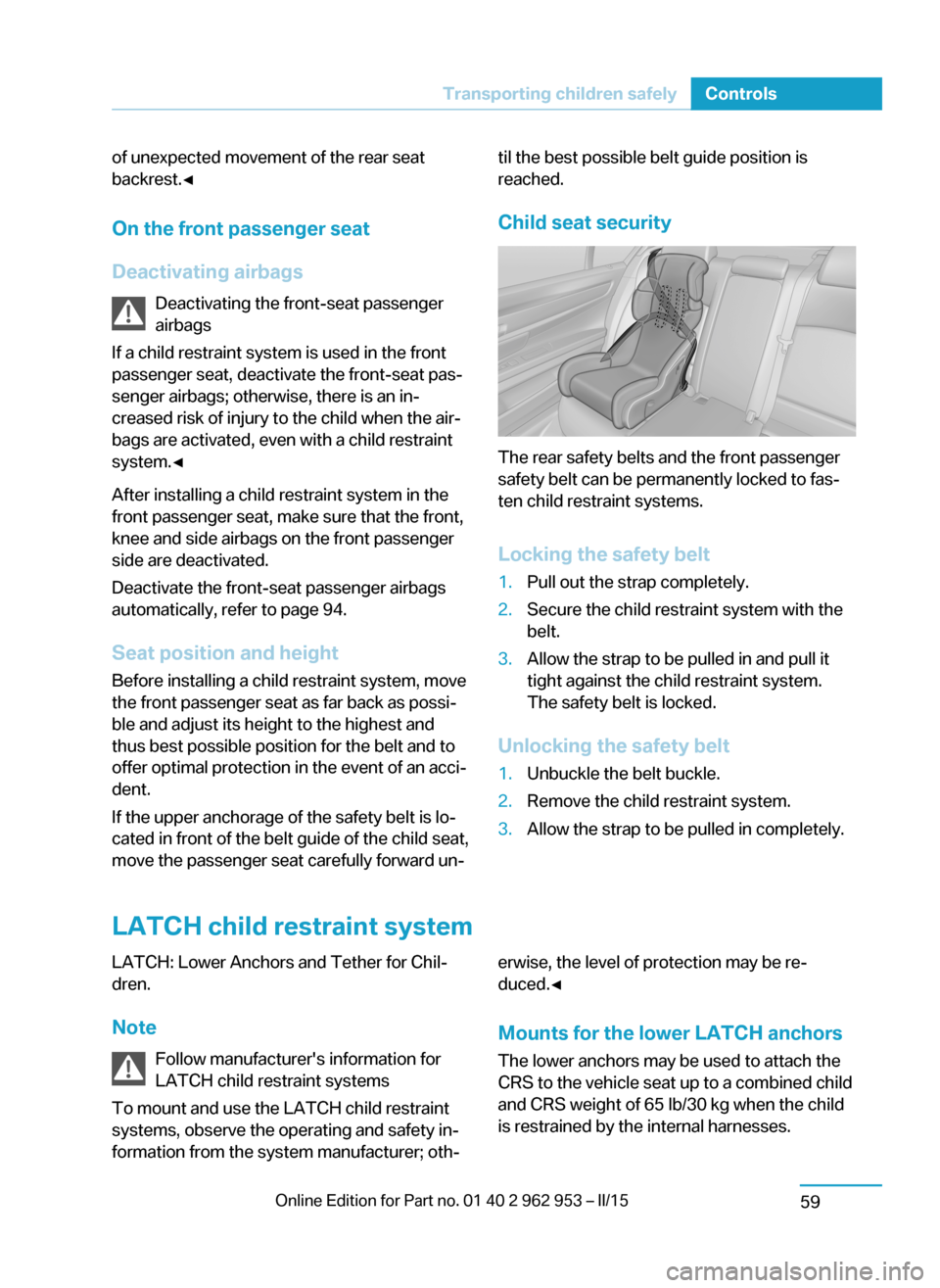
Child seat security
The rear safety belts and the front passenger
safety belt can be permanently locked to fas‐
ten child restraint systems.
Locking the safety belt
1.Pull out the strap completely.2.Secure the child restraint system with the
belt.3.Allow the strap to be pulled in and pull it
tight against the child restraint system.
The safety belt is locked.
Unlocking the safety belt
1.Unbuckle the belt buckle.2.Remove the child restraint system.3.Allow the strap to be pulled in completely.
LATCH child restraint system
LATCH: Lower Anchors and Tether for Chil‐
dren.
Note Follow manufacturer's information for
LATCH child restraint systems
To mount and use the LATCH child restraint
systems, observe the operating and safety in‐
formation from the system manufacturer; oth‐erwise, the level of protection may be re‐
duced.◀
Mounts for the lower LATCH anchors The lower anchors may be used to attach the
CRS to the vehicle seat up to a combined child
and CRS weight of 65 lb/30 kg when the child
is restrained by the internal harnesses.Seite 57Transporting children safelyControls59
Page 72 of 230
Properly engage the lower LATCH an‐
chors
Make sure that the lower LATCH anchors have
properly engaged and that the child restraint
system is resting snugly against the backrest;
otherwise, the degree of protection may be re‐
duced.◀
Before mounting the LATCH child restraint
system, pull the belt away from the child re‐
straint system.
The corresponding symbol shows the
mounts for the lower LATCH anchors.
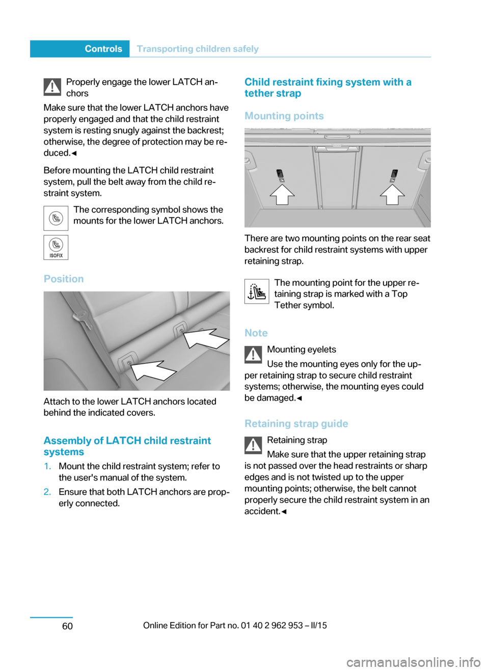
Position
Attach to the lower LATCH anchors located
behind the indicated covers.
Assembly of LATCH child restraint
systems
1.Mount the child restraint system; refer to
the user's manual of the system.2.Ensure that both LATCH anchors are prop‐
erly connected.Child restraint fixing system with a
tether strap
Mounting points
There are two mounting points on the rear seat
backrest for child restraint systems with upper
retaining strap.
The mounting point for the upper re‐
taining strap is marked with a Top
Tether symbol.
Note Mounting eyelets
Use the mounting eyes only for the up‐
per retaining strap to secure child restraint
systems; otherwise, the mounting eyes could
be damaged.◀
Retaining strap guide Retaining strap
Make sure that the upper retaining strap
is not passed over the head restraints or sharp
edges and is not twisted up to the upper
mounting points; otherwise, the belt cannot
properly secure the child restraint system in an
accident.◀
Seite 58ControlsTransporting children safely60
Page 73 of 230
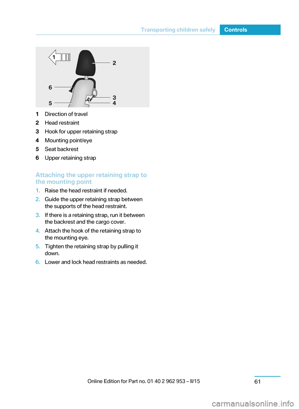
1Direction of travel2Head restraint3Hook for upper retaining strap4Mounting point/eye5Seat backrest6Upper retaining strap
Attaching the upper retaining strap to
the mounting point
1.Raise the head restraint if needed.2.Guide the upper retaining strap between
the supports of the head restraint.3.If there is a retaining strap, run it between
the backrest and the cargo cover.4.Attach the hook of the retaining strap to
the mounting eye.5.Tighten the retaining strap by pulling it
down.6.Lower and lock head restraints as needed.Seite 59Transporting children safelyControls61
Page 74 of 230
DrivingVehicle features and options
This chapter describes all standard, country-
specific and optional features offered with the
series. It also describes features that are not
necessarily available in your car, e. g., due to
the selected options or country versions. This
also applies to safety-related functions and
systems.
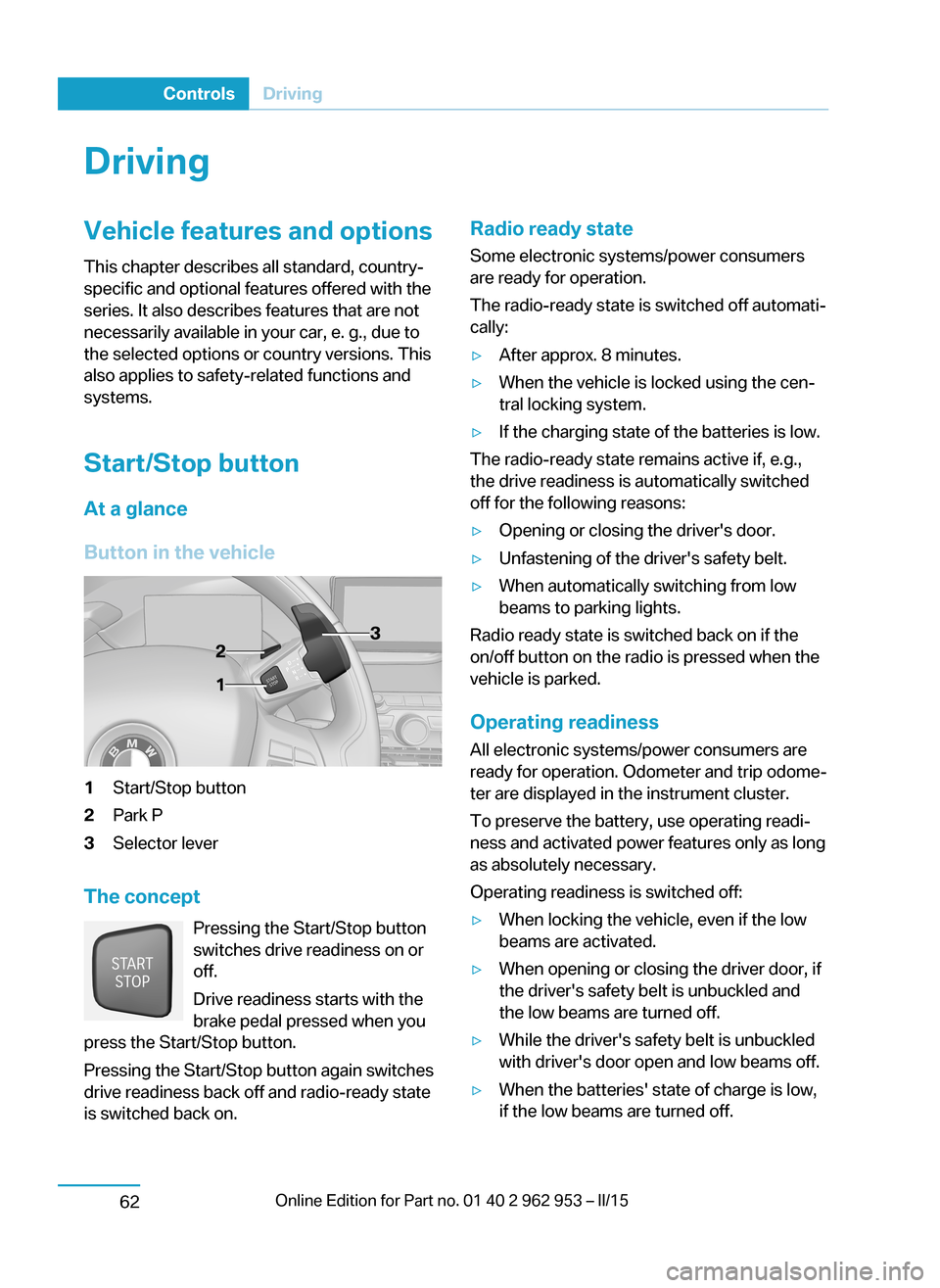
Start/Stop button
At a glance
Button in the vehicle1Start/Stop button2Park P3Selector lever
The concept Pressing the Start/Stop button
switches drive readiness on or
off.
Drive readiness starts with the
brake pedal pressed when you
press the Start/Stop button.
Pressing the Start/Stop button again switches
drive readiness back off and radio-ready state is switched back on.
Radio ready state
Some electronic systems/power consumers
are ready for operation.
The radio-ready state is switched off automati‐ cally:▷After approx. 8 minutes.▷When the vehicle is locked using the cen‐
tral locking system.▷If the charging state of the batteries is low.
The radio-ready state remains active if, e.g.,
the drive readiness is automatically switched
off for the following reasons:
▷Opening or closing the driver's door.▷Unfastening of the driver's safety belt.▷When automatically switching from low
beams to parking lights.
Radio ready state is switched back on if the
on/off button on the radio is pressed when the
vehicle is parked.
Operating readiness
All electronic systems/power consumers are
ready for operation. Odometer and trip odome‐
ter are displayed in the instrument cluster.
To preserve the battery, use operating readi‐
ness and activated power features only as long
as absolutely necessary.
Operating readiness is switched off:
▷When locking the vehicle, even if the low
beams are activated.▷When opening or closing the driver door, if
the driver's safety belt is unbuckled and
the low beams are turned off.▷While the driver's safety belt is unbuckled
with driver's door open and low beams off.▷When the batteries' state of charge is low,
if the low beams are turned off.Seite 60ControlsDriving62
Page 75 of 230
▷The low beams reel to parking lights after
approx. 15 minutes of no use.
Drive readiness
If drive readiness is switched on, the vehicle
ready to drive and the READY signal, refer to
page 63, is displayed in the instrument clus‐
ter.
All vehicle systems are ready for operation.
Most of the indicator and warning lights in the
instrument cluster light up for a varied length
of time.
Activated drive readiness is the equivalent of a
running engine in conventional vehicles. Deac‐
tivated engine readiness is equivalent to
switching the ignition off.
To save battery power when parking, reel off
drive readiness and any unnecessary elec‐
tronic systems/power consumers.
Drive readiness is switched off automatically:
▷When opening or closing the driver door, if
the driver's safety belt is unbuckled.
Note
If drive readiness is switched on, the system
automatically switches to the radio-ready state
when the door is opened and the driver's
safety belt is unbuckled, or if the lights are
turned off or the daytime running lights are ac‐
tivated.
Selector lever position P with drive readi‐
ness switched off
When drive readiness is switched off, selector
lever position P is automatically engaged.
When in an automatic car wash, e.g., ensure
that the drive readiness is not switched off ac‐
cidentally, otherwise, wheels can lock up.◀
Drive readiness in detail
Hints Do not leave the vehicle unattended
Do not leave the vehicle unattended with
drive readiness switched on; otherwise, it may
pose a risk.◀
Before leaving the vehicle
Before leaving the vehicle, with drive
readiness switched on engage lever in position
P P and set the parking brake; otherwise, the
vehicle is not secured against rolling away.◀
Switching on drive readiness1.Close the driver's door.2.Depress the brake pedal.3.Press the Start/Stop button.
Drive readiness is switched on.
Display in the instrument cluster The READY display indicates
that the vehicle is ready for driv‐
ing.
Display on the Start/Stop button
General information
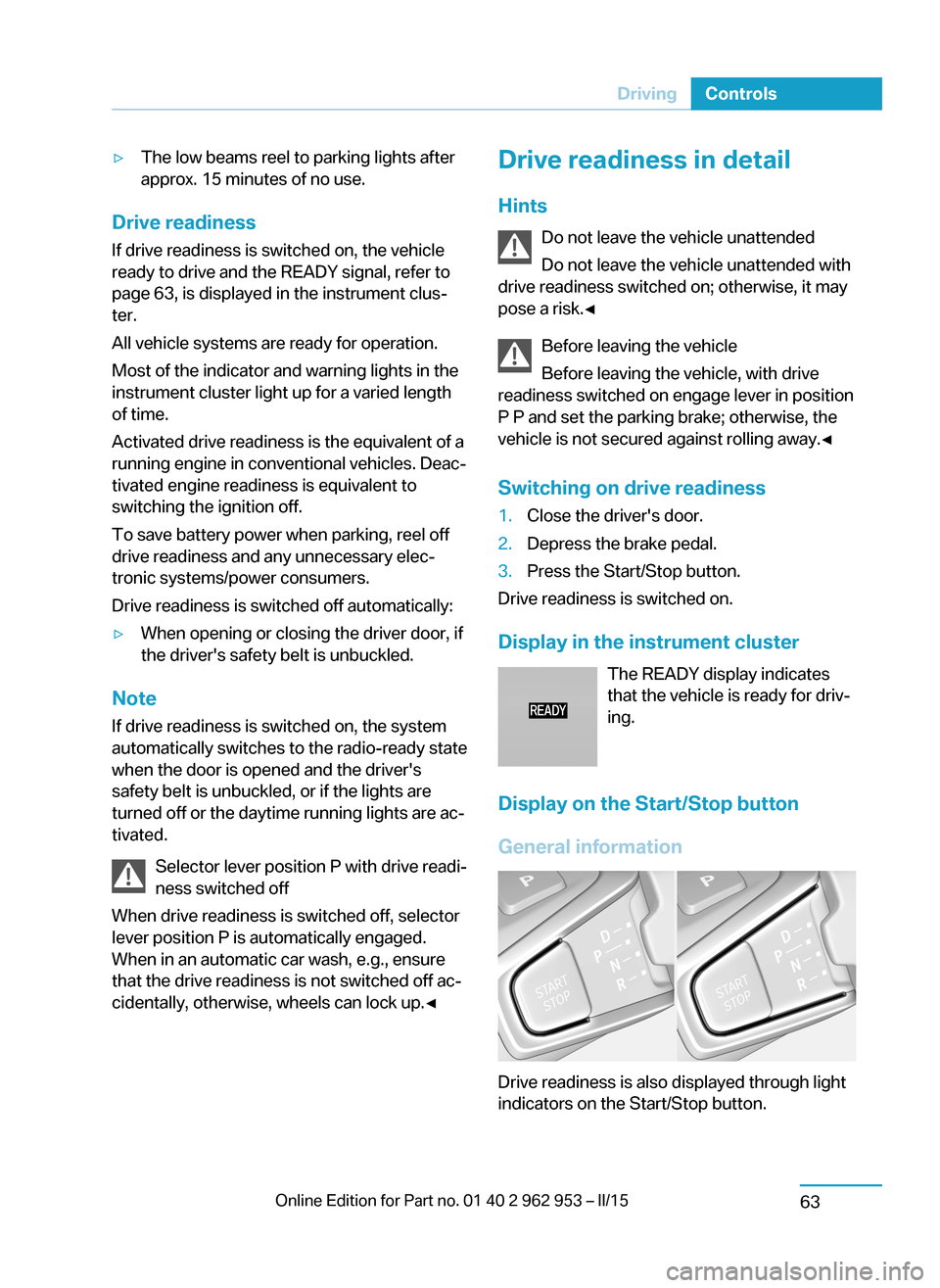
Drive readiness is also displayed through light
indicators on the Start/Stop button.
Seite 61DrivingControls63
Page 76 of 230
Lighting pulses orange▷After unlocking and opening the door.▷After switching off drive readiness.
When the brake pedal is depressed, the light‐
ing becomes more intense.
Lighting lights up steady blue
After drive readiness is switched on, light turns
blue. The vehicle is ready to drive. The READY
indicator lights up in the instrument cluster. In
addition, a signal sounds.
Lighting off
Drive readiness, operating readiness and
radio-ready state are turned off. The vehicle is
in the idle state. The charging cable may be
connected.
Driving off
Requirements
Driving is possible under the following condi‐
tions:
▷The high-voltage battery is sufficiently
charged.▷The driver's door is closed.
sDriving
1.Switch on drive readiness.2.Apply the brake and engage lever in posi‐
tion P D or R.3.Release the parking brake.4.Depress the accelerator pedal to drive.Selector lever positions
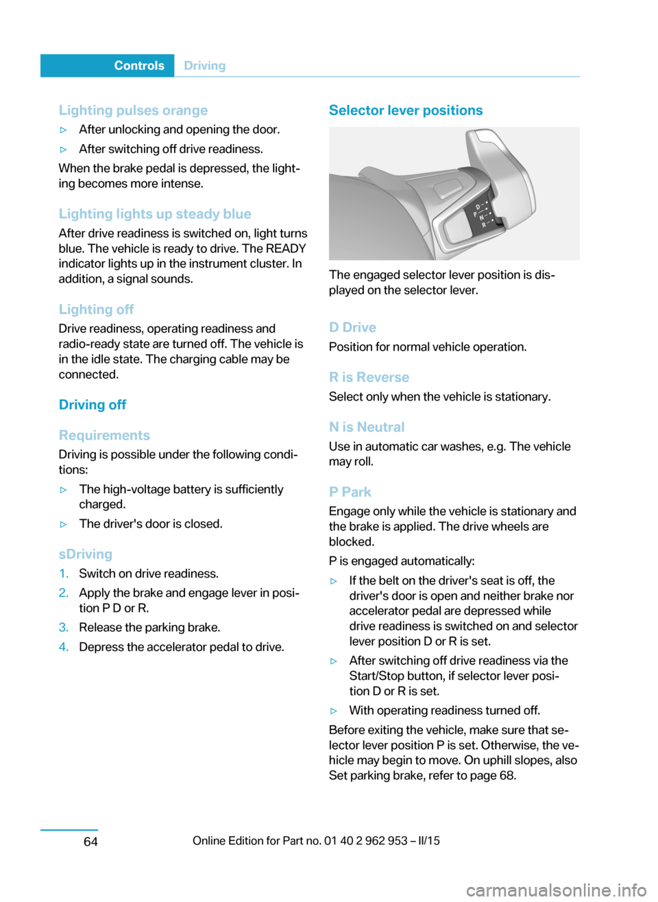
The engaged selector lever position is dis‐
played on the selector lever.
D Drive
Position for normal vehicle operation.
R is Reverse
Select only when the vehicle is stationary.
N is NeutralUse in automatic car washes, e.g. The vehicle
may roll.
P Park Engage only while the vehicle is stationary and
the brake is applied. The drive wheels are
blocked.
P is engaged automatically:
▷If the belt on the driver's seat is off, the
driver's door is open and neither brake nor
accelerator pedal are depressed while
drive readiness is switched on and selector
lever position D or R is set.▷After switching off drive readiness via the
Start/Stop button, if selector lever posi‐
tion D or R is set.▷With operating readiness turned off.
Before exiting the vehicle, make sure that se‐
lector lever position P is set. Otherwise, the ve‐
hicle may begin to move. On uphill slopes, also
Set parking brake, refer to page 68.
Seite 62ControlsDriving64
Page 77 of 230
Engaging selector lever positions
General information▷Interlock: the selector lever position P can
be exited only with drive readiness en‐
gaged.▷Shift lock: with the vehicle stationary, press
on the brake pedal before shifting out of P
or N; otherwise, the shift command will not
be executed.▷Shift lock: before shifting out of P, remove
the charging cable from the vehicle; other‐
wise, the shift command will not be exe‐
cuted.
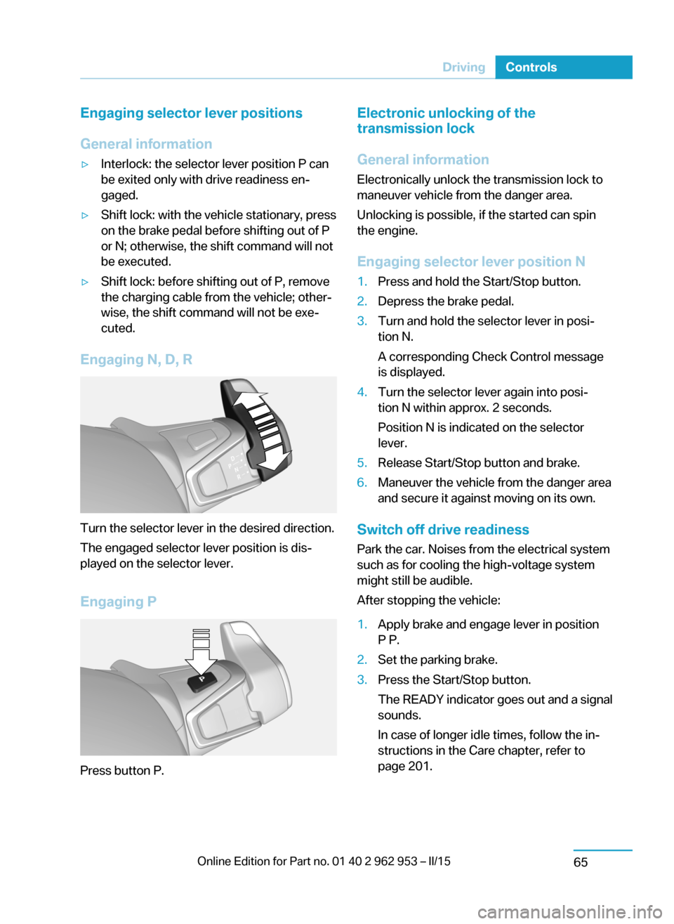
Engaging N, D, R
Turn the selector lever in the desired direction.
The engaged selector lever position is dis‐
played on the selector lever.
Engaging P
Press button P.
Electronic unlocking of the
transmission lock
General information
Electronically unlock the transmission lock to
maneuver vehicle from the danger area.
Unlocking is possible, if the started can spin
the engine.
Engaging selector lever position N1.Press and hold the Start/Stop button.2.Depress the brake pedal.3.Turn and hold the selector lever in posi‐
tion N.
A corresponding Check Control message
is displayed.4.Turn the selector lever again into posi‐
tion N within approx. 2 seconds.
Position N is indicated on the selector
lever.5.Release Start/Stop button and brake.6.Maneuver the vehicle from the danger area
and secure it against moving on its own.
Switch off drive readiness
Park the car. Noises from the electrical system
such as for cooling the high-voltage system might still be audible.
After stopping the vehicle:
1.Apply brake and engage lever in position
P P.2.Set the parking brake.3.Press the Start/Stop button.
The READY indicator goes out and a signal
sounds.
In case of longer idle times, follow the in‐
structions in the Care chapter, refer to
page 201.Seite 63DrivingControls65
Page 78 of 230
Before driving into a car wash
So that the vehicle can roll into a car wash ob‐
serve instructions for going into an automatic
car wash, refer to page 198.
Driving in detail: eDRIVE
Hints Awareness of vehicle reduced when
driven in electric mode
When driving in electric mode, note that, due
to the lack of engine noise, pedestrians and
other traffic might pay less attention to the ve‐
hicle due to missing engine noises. Please
take special care when parking or leaving a
parking space.◀
Cautiously remove your foot from the ac‐
celerator pedal
Cautiously remove your foot from the acceler‐
ator pedal because the braking effect of the
electric motor can be stronger than with a
combustion engine. Otherwise, abrupt braking
and slow-down may confuse other traffic.◀
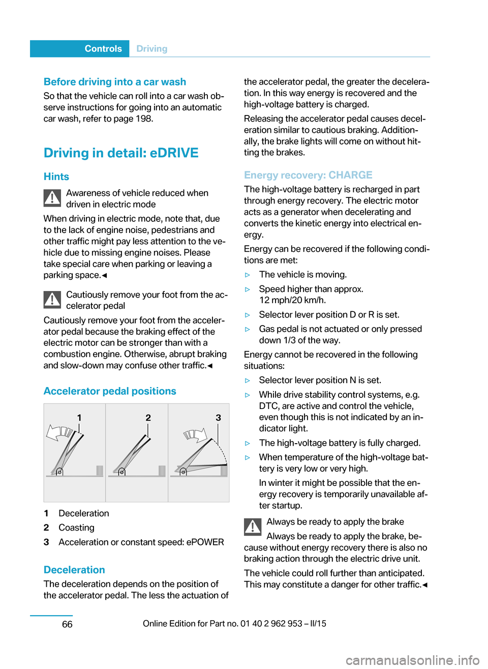
Accelerator pedal positions1Deceleration2Coasting3Acceleration or constant speed: ePOWER
Deceleration
The deceleration depends on the position of
the accelerator pedal. The less the actuation of
the accelerator pedal, the greater the decelera‐
tion. In this way energy is recovered and the
high-voltage battery is charged.
Releasing the accelerator pedal causes decel‐
eration similar to cautious braking. Addition‐
ally, the brake lights will come on without hit‐
ting the brakes.
Energy recovery: CHARGE The high-voltage battery is recharged in part
through energy recovery. The electric motor
acts as a generator when decelerating and
converts the kinetic energy into electrical en‐
ergy.
Energy can be recovered if the following condi‐
tions are met:▷The vehicle is moving.▷Speed higher than approx.
12 mph/20 km/h.▷Selector lever position D or R is set.▷Gas pedal is not actuated or only pressed
down 1/3 of the way.
Energy cannot be recovered in the following
situations:
▷Selector lever position N is set.▷While drive stability control systems, e.g.
DTC, are active and control the vehicle,
even though this is not indicated by an in‐
dicator light.▷The high-voltage battery is fully charged.▷When temperature of the high-voltage bat‐
tery is very low or very high.
In winter it might be possible that the en‐
ergy recovery is temporarily unavailable af‐
ter startup.
Always be ready to apply the brake
Always be ready to apply the brake, be‐
cause without energy recovery there is also no
braking action through the electric drive unit.
The vehicle could roll further than anticipated.
This may constitute a danger for other traffic.◀
Seite 64ControlsDriving66
Page 79 of 230
Exemplary traffic situations
If a deceleration operation is foreseeable while
driving, this can be used for energy recovery.
The following exemplary driving situations may
show that:▷Decelerating downhill.▷Deceleration before a red light.
Avoid late or abrupt braking. Instead, deceler‐
ate the vehicle using energy recovery.
Coasting
The electric drive makes it possible to roll with‐
out consuming energy. This driving condition
is referred to as coasting.
Proactive driving reduces energy consumption
and increases the range.
With vehicle rolling, READY is displayed in the
instrument cluster. With vehicle rolling, no en‐
ergy is recovered.
Exemplary traffic situations
If a route can be traveled without anticipated
need for braking, it is advantageous to roll.
The following exemplary driving situations may
show that:
▷Rolling on a straight downhill route without
obstacles.▷Coasting on a route without obstacles.
Avoid late or abrupt braking.
Range Extender
Increase range
If the charging state of the high-voltage battery
drops during travel to a minimum value, the
Range Extender starts and supplies the re‐
quired electrical energy for driving on.
The symbol on the charging state indicator
designates a Range Extender reel-on time.
The Range Extender controls its output auto‐
matically, turns itself off and restarts according
to the driving situation.
The high-voltage battery will not be charged
by the Range Extender.
Automatic maintenance run
To ensure that the Range Extender functions
properly even during longer periods of non- use, the Range Extender is automatically acti‐
vated for a few minutes at certain intervals dur‐
ing the trip. Respective Check Control
messages indicate the dry run. Should that oc‐
cur at an unfavorable time you may cancel the
dry run by pressing the Start/Stop button. It
postpones the dry run.
Should the high-voltage battery be fully
charged or if there is not enough gas in the
tank then a dry run will not be executed.
Heavily discharged high-voltage
battery
If the high-voltage battery is heavily dis‐
charged during the trip, the performance and
some comfort features are reduced step-by-
step to extend the range.
Heated high-voltage batteryWith a stationary dirt In exceptional cases, it is possible that the
high-voltage battery heats up sharply when the
vehicle is stationary. E. g. with extreme exter‐
nal temperatures and direct solar radiation.
With a overheated high-voltage battery, drive
readiness cannot be switched on.
A Check Control message is displayed.
Another message will indicate when drive readiness is available again.
While driving
If the high-voltage battery overheats during the
trip, the performance is reduced step-by-step
in order to cool down the battery. The ePO‐
WER performance display in the instrument
cluster returns in the process. When tempera‐
ture increases further, park the vehicle until theSeite 65DrivingControls67
Page 80 of 230
high-voltage batter has cooled down. Should
the performance display fall to 0, drive readi‐
ness is switched off and the vehicle comes to a
stop.
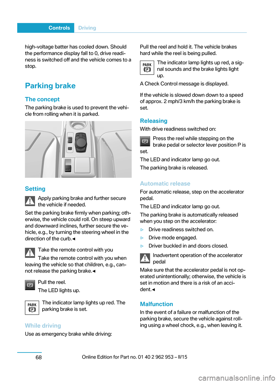
Parking brake The conceptThe parking brake is used to prevent the vehi‐
cle from rolling when it is parked.
Setting
Apply parking brake and further secure
the vehicle if needed.
Set the parking brake firmly when parking; oth‐
erwise, the vehicle could roll. On steep upward
and downward inclines, further secure the ve‐
hicle, e.g., by turning the steering wheel in the
direction of the curb.◀
Take the remote control with you
Take the remote control with you when
leaving the vehicle so that children, e.g., can‐
not release the parking brake.◀
Pull the reel.
The LED lights up.
The indicator lamp lights up red. The
parking brake is set.
While driving
Use as emergency brake while driving:
Pull the reel and hold it. The vehicle brakes
hard while the reel is being pulled.
The indicator lamp lights up red, a sig‐
nal sounds and the brake lights light
up.
A Check Control message is displayed.
If the vehicle is slowed down down to a speed
of approx. 2 mph/3 km/h the parking brake is
set.
Releasing
With drive readiness switched on:
Press the reel while stepping on the
brake pedal or selector lever position P is
set.
The LED and indicator lamp go out.
The parking brake is released.
Automatic release For automatic release, step on the accelerator
pedal.
The LED and indicator lamp go out.
The parking brake is automatically released
when you step on the accelerator:▷Drive readiness switched on.▷Drive mode engaged.▷Driver buckled in and doors closed.
Inadvertent operation of the accelerator
pedal
Make sure that the accelerator pedal is not op‐
erated unintentionally; otherwise, the vehicle is
set in motion and there is a risk of an acci‐
dent.◀
Malfunction In the event of a failure or malfunction of the
parking brake, secure the vehicle against roll‐
ing using a wheel chock, e.g., when leaving it.
Seite 66ControlsDriving68