BMW I3 2015 I01 Owner's Manual
Manufacturer: BMW, Model Year: 2015, Model line: I3, Model: BMW I3 2015 I01Pages: 236, PDF Size: 17.6 MB
Page 191 of 236
Uniform Tire Quality GradingQuality grades can be found where applicable
on the tire sidewall between tread shoulder
and maximum section width.
For example: Treadwear 200; Traction AA;
Temperature A
DOT Quality Grades
Treadwear
Traction AA A B C
Temperature A B C
All passenger car tires must conform to Fed‐
eral Safety Requirements in addition to these
grades.
TreadwearThe treadwear grade is a comparative rating
based on the wear rate of the tire when tested
under controlled conditions on a specified gov‐
ernment test course. For example, a tire
graded 150 would wear one and one-half, 1 g,
times as well on the government course as a
tire graded 100. The relative performance of
tires depends upon the actual conditions of
their use, however, and may depart signifi‐
cantly from the norm due to variations in driv‐
ing habits, service practices and differences in
road characteristics and climate.
Traction
The traction grades, from highest to lowest,
are AA, A, B, and C.
Those grades represent the tire's ability to
stop on wet pavement as measured under
controlled conditions on specified government
test surfaces of asphalt and concrete. A tire
marked C may have poor traction performance.
The traction grade assigned to this tire is
based on straight-ahead braking traction tests,
and does not include acceleration, cornering,
hydroplaning, or peak traction characteristics.Temperature
The temperature grades are A, the highest, B,
and C, representing the tire's resistance to the
generation of heat and its ability to dissipate
heat when tested under controlled conditions
on a specified indoor laboratory test wheel.
Sustained high temperature can cause the ma‐
terial of the tire to degenerate and reduce tire
life, and excessive temperature can lead to
sudden tire failure. The grade C corresponds
to a level of performance which all passenger
car tires must meet under the Federal Motor
Vehicle Safety Standard No. 109. Grades Band
A represent higher levels of performance on
the laboratory test wheel than the minimum re‐
quired by law.
Temperature grade for this tire
The temperature grade for this tire is es‐
tablished for a tire that is properly inflated and
not overloaded. Excessive speed, underinfla‐
tion, or excessive loading, either separately or
in combination, can cause heat buildup and
possible tire failure.
If necessary, have the vehicle towed.◀
M+S
Winter and all-season tires with better cold
weather performance than summer tires.
Tire tread
Summer tires
Do not drive with a tire tread depth of less than
0.12 in/3 mm.
There is an increased danger of hydroplaning if
the tire tread depth is less than 0.12 in/3 mm.
Winter tires
Do not drive with a tire tread depth of less than
0.16 in/4 mm.
Below a tread depth of 0.16 in/4 mm, tires are
less suitable for winter operation.Seite 175Wheels and tiresMobility175
Online Edition for Part no. 01 40 2 960 865 - II/15
Page 192 of 236
Minimum tread depth
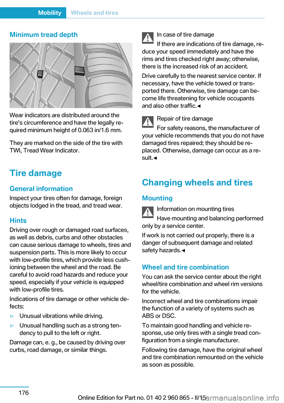
Wear indicators are distributed around the
tire's circumference and have the legally re‐
quired minimum height of 0.063 in/1.6 mm.
They are marked on the side of the tire with
TWI, Tread Wear Indicator.
Tire damage
General information
Inspect your tires often for damage, foreign
objects lodged in the tread, and tread wear.
Hints
Driving over rough or damaged road surfaces,
as well as debris, curbs and other obstacles
can cause serious damage to wheels, tires and
suspension parts. This is more likely to occur
with low-profile tires, which provide less cush‐
ioning between the wheel and the road. Be
careful to avoid road hazards and reduce your
speed, especially if your vehicle is equipped
with low-profile tires.
Indications of tire damage or other vehicle de‐
fects:
▷Unusual vibrations while driving.▷Unusual handling such as a strong ten‐
dency to pull to the left or right.
Damage can, e. g., be caused by driving over
curbs, road damage, or similar things.
In case of tire damage
If there are indications of tire damage, re‐
duce your speed immediately and have the
rims and tires checked right away; otherwise,
there is the increased risk of an accident.
Drive carefully to the nearest service center. If
necessary, have the vehicle towed or trans‐
ported there. Otherwise, tire damage can be‐
come life threatening for vehicle occupants
and also other traffic.◀
Repair of tire damage
For safety reasons, the manufacturer of
your vehicle recommends that you do not have
damaged tires repaired; they should be re‐
placed. Otherwise, damage can occur as a re‐
sult.◀
Changing wheels and tires
Mounting Information on mounting tires
Have mounting and balancing performed
only by a service center.
If work is not carried out properly, there is a
danger of subsequent damage and related
safety hazards.◀
Wheel and tire combination
You can ask the service center about the right
wheel/tire combination and wheel rim versions
for the vehicle.
Incorrect wheel and tire combinations impair
the function of a variety of systems such as
ABS or DSC.
To maintain good handling and vehicle re‐
sponse, use only tires with a single tread con‐
figuration from a single manufacturer.
Following tire damage, have the original wheel
and tire combination remounted on the vehicle
as soon as possible.Seite 176MobilityWheels and tires176
Online Edition for Part no. 01 40 2 960 865 - II/15
Page 193 of 236
Approved wheels and tires
You should only use wheels and tires
that have been approved by the vehicle manu‐
facturer for your vehicle type; otherwise, e.g.,
despite having the same official size ratings,
variations can lead to chassis contact and with
it, the risk of severe accidents
The manufacturer of your vehicle cannot eval‐
uate non-approved wheels and tires to deter‐
mine if they are suited for use, and therefore
cannot guarantee the operating safety of the
vehicle.◀
Recommended tire brands
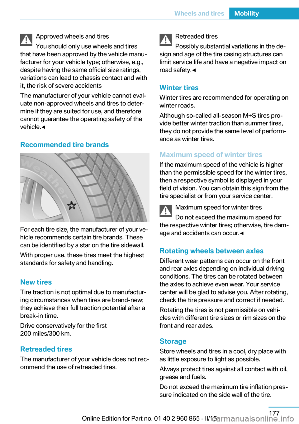
For each tire size, the manufacturer of your ve‐
hicle recommends certain tire brands. These
can be identified by a star on the tire sidewall.
With proper use, these tires meet the highest
standards for safety and handling.
New tires Tire traction is not optimal due to manufactur‐
ing circumstances when tires are brand-new;
they achieve their full traction potential after a
break-in time.
Drive conservatively for the first
200 miles/300 km.
Retreaded tires
The manufacturer of your vehicle does not rec‐
ommend the use of retreaded tires.
Retreaded tires
Possibly substantial variations in the de‐
sign and age of the tire casing structures can
limit service life and have a negative impact on
road safety.◀
Winter tires
Winter tires are recommended for operating on
winter roads.
Although so-called all-season M+S tires pro‐
vide better winter traction than summer tires, they do not provide the same level of perform‐
ance as winter tires.
Maximum speed of winter tires If the maximum speed of the vehicle is higher
than the permissible speed for the winter tires,
then a respective symbol is displayed in your
field of vision. You can obtain this sign from the
tire specialist or from your service center.
Maximum speed for winter tires
Do not exceed the maximum speed for
the respective winter tires; otherwise, tire dam‐
age and accidents can occur.◀
Rotating wheels between axles Different wear patterns can occur on the front
and rear axles depending on individual driving
conditions. The tires can be rotated between
the axles to achieve even wear. Your service
center will be glad to advise you. After rotating,
check the tire pressure and correct if needed.
Rotating the tires is not permissible on vehi‐
cles with different tire sizes or rim sizes on the
front and rear axles.
StorageStore wheels and tires in a cool, dry place with
as little exposure to light as possible.
Always protect tires against all contact with oil,
grease and fuels.
Do not exceed the maximum tire inflation pres‐
sure indicated on the side wall of the tire.Seite 177Wheels and tiresMobility177
Online Edition for Part no. 01 40 2 960 865 - II/15
Page 194 of 236
Mobility SystemThe concept
With the Mobility System, minor tire damage
can be sealed quickly to enable continued
travel. To accomplish this, sealant is pumped
into the tires, which seals the damage from the
inside.
The compressor can be used to check the tire
inflation pressure.
Hints▷Follow the instructions on using the Mobi‐
lity System found on the compressor and
sealant container.▷Use of the Mobility System may be ineffec‐
tive if the tire puncture measures approx.
1/8 in/4 mm or more.▷Contact the nearest service center if the
tire cannot be made drivable.▷If possible, do not remove foreign bodies
that have penetrated the tire.▷Pull the speed limit sticker off the sealant
container and apply it to the steering
wheel.▷The use of a sealant can damage the TPM
wheel electronics. In this case, have the
electronics checked at the next opportu‐
nity and have them replaced if needed.
Storage
The mobility system is located in the storage
compartment under the hood.
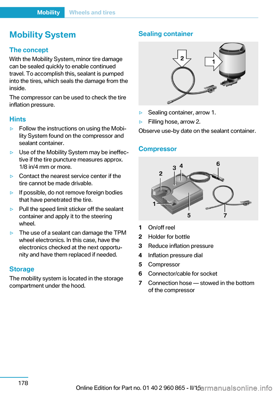
Sealing container▷Sealing container, arrow 1.▷Filling hose, arrow 2.
Observe use-by date on the sealant container.
Compressor
1On/off reel2Holder for bottle3Reduce inflation pressure4Inflation pressure dial5Compressor6Connector/cable for socket7Connection hose — stowed in the bottom
of the compressorSeite 178MobilityWheels and tires178
Online Edition for Part no. 01 40 2 960 865 - II/15
Page 195 of 236
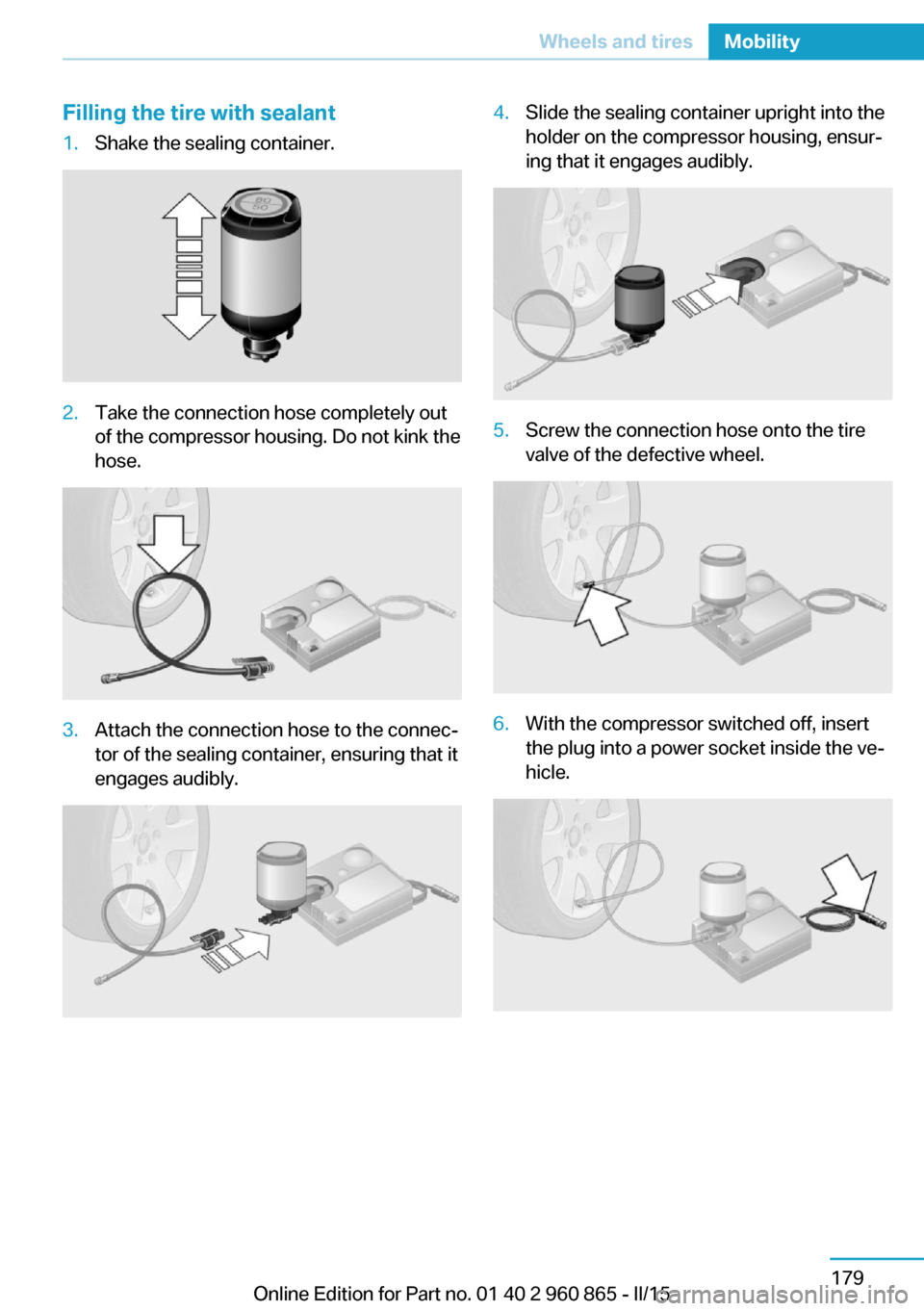
Filling the tire with sealant1.Shake the sealing container.2.Take the connection hose completely out
of the compressor housing. Do not kink the
hose.3.Attach the connection hose to the connec‐
tor of the sealing container, ensuring that it
engages audibly.4.Slide the sealing container upright into the
holder on the compressor housing, ensur‐
ing that it engages audibly.5.Screw the connection hose onto the tire
valve of the defective wheel.6.With the compressor switched off, insert
the plug into a power socket inside the ve‐
hicle.Seite 179Wheels and tiresMobility179
Online Edition for Part no. 01 40 2 960 865 - II/15
Page 196 of 236
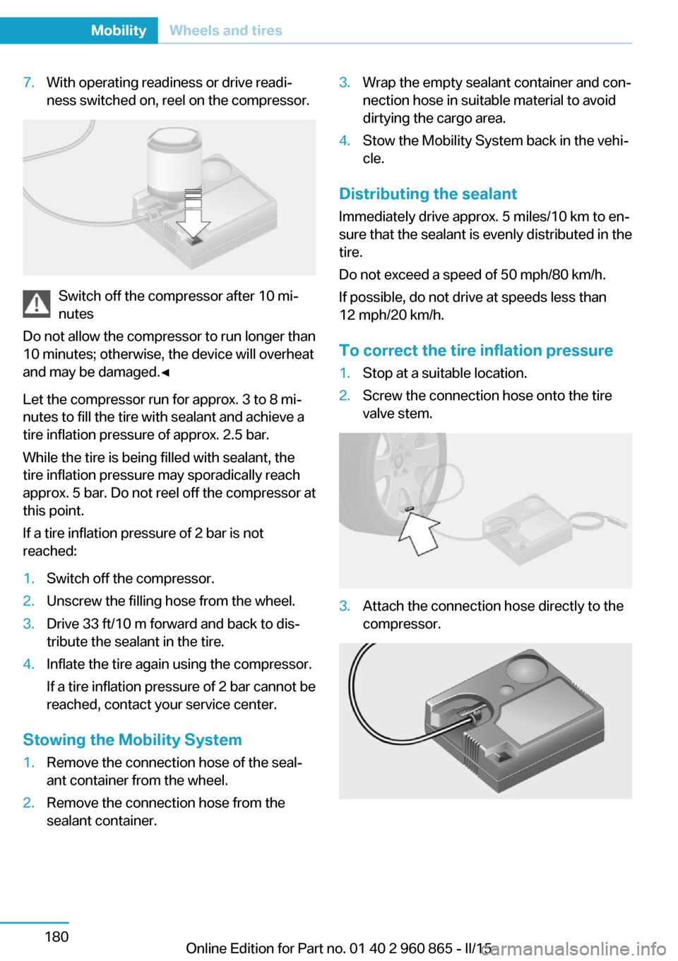
7.With operating readiness or drive readi‐
ness switched on, reel on the compressor.
Switch off the compressor after 10 mi‐
nutes
Do not allow the compressor to run longer than
10 minutes; otherwise, the device will overheat
and may be damaged.◀
Let the compressor run for approx. 3 to 8 mi‐
nutes to fill the tire with sealant and achieve a
tire inflation pressure of approx. 2.5 bar.
While the tire is being filled with sealant, the
tire inflation pressure may sporadically reach
approx. 5 bar. Do not reel off the compressor at
this point.
If a tire inflation pressure of 2 bar is not
reached:
1.Switch off the compressor.2.Unscrew the filling hose from the wheel.3.Drive 33 ft/10 m forward and back to dis‐
tribute the sealant in the tire.4.Inflate the tire again using the compressor.
If a tire inflation pressure of 2 bar cannot be
reached, contact your service center.
Stowing the Mobility System
1.Remove the connection hose of the seal‐
ant container from the wheel.2.Remove the connection hose from the
sealant container.3.Wrap the empty sealant container and con‐
nection hose in suitable material to avoid
dirtying the cargo area.4.Stow the Mobility System back in the vehi‐
cle.
Distributing the sealant
Immediately drive approx. 5 miles/10 km to en‐
sure that the sealant is evenly distributed in the
tire.
Do not exceed a speed of 50 mph/80 km/h.
If possible, do not drive at speeds less than
12 mph/20 km/h.
To correct the tire inflation pressure
1.Stop at a suitable location.2.Screw the connection hose onto the tire
valve stem.3.Attach the connection hose directly to the
compressor.Seite 180MobilityWheels and tires180
Online Edition for Part no. 01 40 2 960 865 - II/15
Page 197 of 236
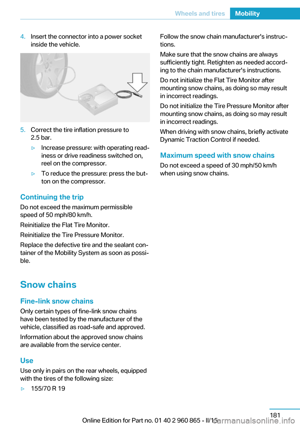
4.Insert the connector into a power socket
inside the vehicle.5.Correct the tire inflation pressure to
2.5 bar.▷Increase pressure: with operating read‐
iness or drive readiness switched on,
reel on the compressor.▷To reduce the pressure: press the but‐
ton on the compressor.
Continuing the trip
Do not exceed the maximum permissible
speed of 50 mph/80 km/h.
Reinitialize the Flat Tire Monitor.
Reinitialize the Tire Pressure Monitor.
Replace the defective tire and the sealant con‐
tainer of the Mobility System as soon as possi‐
ble.
Snow chains Fine-link snow chains
Only certain types of fine-link snow chains
have been tested by the manufacturer of the
vehicle, classified as road-safe and approved.
Information about the approved snow chains
are available from the service center.
Use
Use only in pairs on the rear wheels, equipped
with the tires of the following size:
▷155/70 R 19Follow the snow chain manufacturer's instruc‐
tions.
Make sure that the snow chains are always
sufficiently tight. Retighten as needed accord‐
ing to the chain manufacturer's instructions.
Do not initialize the Flat Tire Monitor after
mounting snow chains, as doing so may result
in incorrect readings.
Do not initialize the Tire Pressure Monitor after
mounting snow chains, as doing so may result
in incorrect readings.
When driving with snow chains, briefly activate
Dynamic Traction Control if needed.
Maximum speed with snow chains Do not exceed a speed of 30 mph/50 km/hwhen using snow chains.Seite 181Wheels and tiresMobility181
Online Edition for Part no. 01 40 2 960 865 - II/15
Page 198 of 236
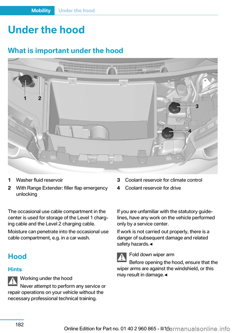
Under the hoodWhat is important under the hood1Washer fluid reservoir2With Range Extender: filler flap emergency
unlocking3Coolant reservoir for climate control4Coolant reservoir for driveThe occasional use cable compartment in the
center is used for storage of the Level 1 charg‐
ing cable and the Level 2 charging cable.
Moisture can penetrate into the occasional use
cable compartment, e.g. in a car wash.
Hood Hints Working under the hood
Never attempt to perform any service or
repair operations on your vehicle without the
necessary professional technical training.If you are unfamiliar with the statutory guide‐
lines, have any work on the vehicle performed
only by a service center.
If work is not carried out properly, there is a
danger of subsequent damage and related
safety hazards.◀
Fold down wiper arm
Before opening the hood, ensure that the
wiper arms are against the windshield, or this
may result in damage.◀Seite 182MobilityUnder the hood182
Online Edition for Part no. 01 40 2 960 865 - II/15
Page 199 of 236
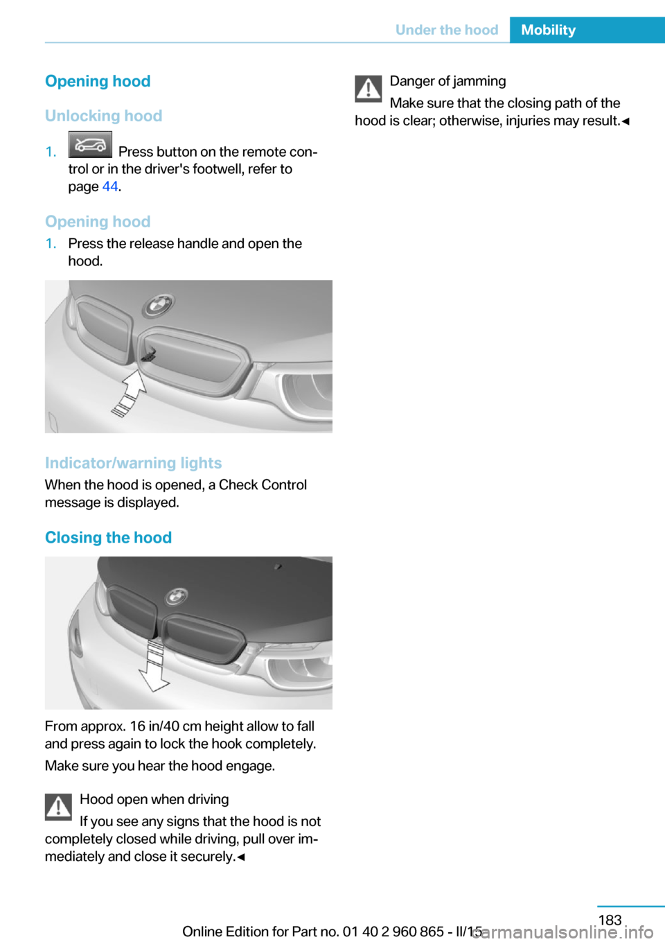
Opening hood
Unlocking hood1. Press button on the remote con‐
trol or in the driver's footwell, refer to
page 44.
Opening hood
1.Press the release handle and open the
hood.
Indicator/warning lights
When the hood is opened, a Check Control
message is displayed.
Closing the hood
From approx. 16 in/40 cm height allow to fall
and press again to lock the hook completely.
Make sure you hear the hood engage.
Hood open when driving
If you see any signs that the hood is not
completely closed while driving, pull over im‐
mediately and close it securely.◀
Danger of jamming
Make sure that the closing path of the
hood is clear; otherwise, injuries may result.◀Seite 183Under the hoodMobility183
Online Edition for Part no. 01 40 2 960 865 - II/15
Page 200 of 236
Engine oilVehicle features and options
This chapter describes all standard, country-
specific and optional features offered with the
series. It also describes features that are not
necessarily available in your car, e. g., due to
the selected options or country versions. This
also applies to safety-related functions and
systems. The respectively applicable country
provisions must be observed when using the
respective features and systems.
General information Engine oil consumption depends on the fre‐
quency of Range Extender use. Therefore,
regularly check the engine oil level after refuel‐
ing.
Checking the oil level NoteCheck the engine oil level with Range Extender
warmed up to operating temperature.
After switching off the Range Extender, wait
several minutes before checking the oil level
so that the engine oil can collect in the oil pan.
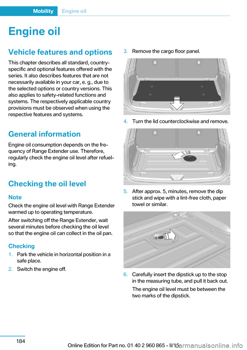
Checking1.Park the vehicle in horizontal position in a
safe place.2.Switch the engine off.3.Remove the cargo floor panel.4.Turn the lid counterclockwise and remove.5.After approx. 5, minutes, remove the dip
stick and wipe with a lint-free cloth, paper
towel or similar.6.Carefully insert the dipstick up to the stop
in the measuring tube, and pull it back out.
The engine oil level must be between the
two marks of the dipstick.Seite 184MobilityEngine oil184
Online Edition for Part no. 01 40 2 960 865 - II/15